⎯⎯ Timer Relay
Timer Relay for DIN Rail Control and Automation
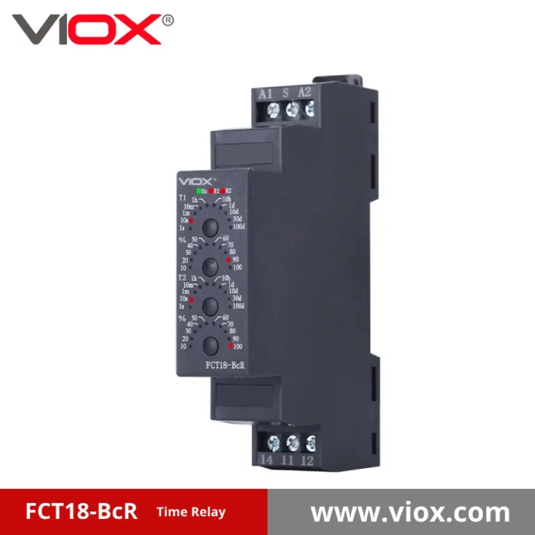
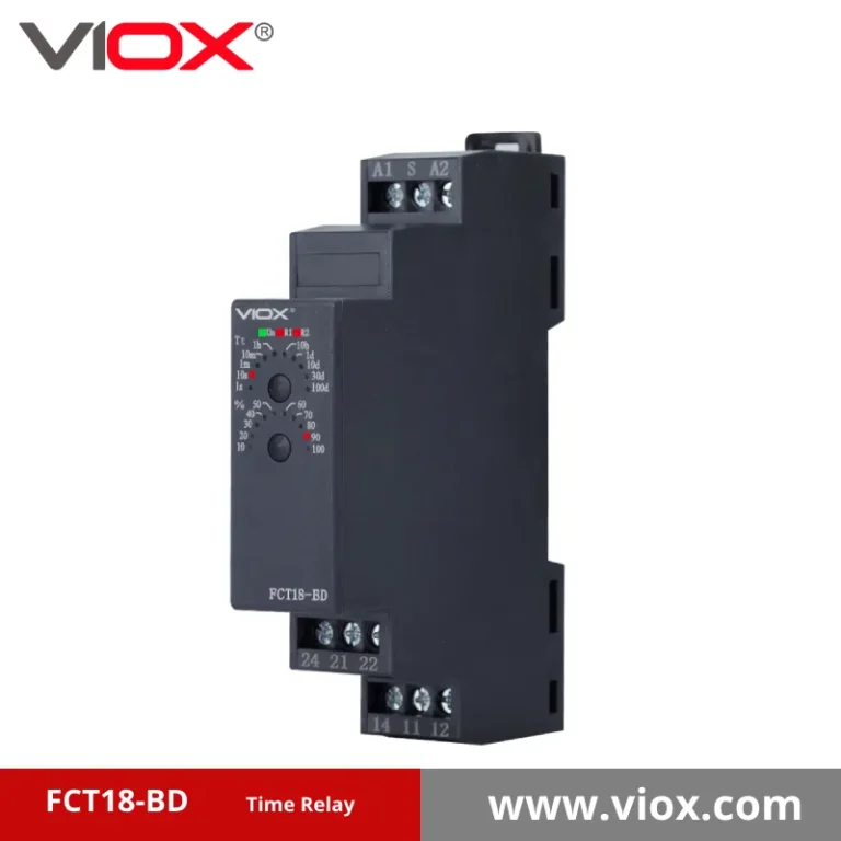
VIOX timer relay products cover the practical timing functions most often used in control panels, machine sequencing, motor auxiliary logic, lighting control, ventilation timing, pump changeover, and automation circuits. The FCT18 range includes on-delay, off-delay, pulse, interval, bistable, flashing, and multifunction time relay options in a compact DIN rail format.
FCT18
Core timer relay platform
12-240V
AC/DC supply coverage
16A
Standard output contact rating
0.5%
Timing accuracy reference
- On-Delay + Off-Delay
- Interval + Pulse + Flashing
- DIN Rail 18mm Direction
- AC/DC 12V-240V
⎯⎯ Overview
What Is a Timer Relay?
A timer relay, also called a time relay or time delay relay, is a control relay that changes contact state after a preset time interval. It is used when a circuit needs delayed switching, controlled release, cyclic output, flashing signal logic, sequence timing, or repeat interval control instead of immediate contact action.
In practical panel work, timer relays are selected by timing function first, then by control voltage, contact rating, mounting format, and application logic. This is especially important in automation cabinets, motor control circuits, lighting sequences, pump and fan systems, and compact DIN rail installations where timing behavior needs to be predictable and repeatable.
The VIOX FCT18 timer relay range is built around the most frequently used timing modes in industrial control. The focus stays on timer relay functions such as on-delay, off-delay, interval, pulse, flashing, and sequence timing so model comparison remains clear and application matching is faster.
Core Timer Relay Specifications
| Product Platform | FCT18 timer relay series |
|---|---|
| Supply Voltage | AC/DC 12V to 240V |
| Output Rating | Typical 16A control contact |
| Timing Accuracy | Approx. ±0.5% reference |
| Repeat Accuracy | Approx. ±0.1% reference |
| Installation | DIN rail modular format |
⎯⎯ Product Range
Core FCT18 Timer Relay Models
Single Function
Pulse Delayed
Interval
Off-Delay
Asymmetrical Delay
Bistable
Flashing
Double Interval
⎯⎯ Function Matrix
Timer Relay Function Coverage
Different timing functions are suited to different control tasks. This matrix makes it easier to compare the main timer relay function groups before confirming the exact model.
| Series | Primary Timing Function | Best Fit |
|---|---|---|
| FCT18-A/At | General on-delay and pulse-delayed timing logic | Basic sequence delay, controlled start, and standard automation timing |
| FCT18-B/Bt | Off-delay and interval timing logic | Controlled stop timing, delayed release, and timed output windows |
| FCT18-M / N / X | Extended multifunction timing families | Applications that need broader timing mode choice in one DIN rail relay platform |
| FCT18-2T / S / P | Cycle, pulse, and specialized sequence timing | Repetitive control logic, periodic switching, and machine timing sequences |
| FCT18-RL / ST | Star-delta and application-specific timing modes | Motor auxiliary control and structured control sequence switching |
| AgR / AdR / AKR / AR / Ata | Pulse-delayed and control-signal-based timing | Projects needing trigger-based timing response and controlled actuation delay |
| WgR / Xd | Asymmetrical on-delay and off-delay timing | Systems requiring non-symmetrical timing behavior between energizing and release |
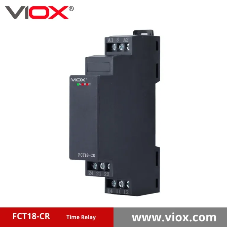
| BR / BgF / BD / CR / BcR / AcR | Interval, flashing, double interval, and bistable timing | Warning systems, cyclic signals, staged timing, and specialized panel control logic |
⎯⎯ Selection Factors
Key Points for Timer Relay Selection
Timer relay selection usually comes down to a few practical points: timing function, supply voltage, output contact capability, and the way the control signal needs to behave in the circuit.
Timing Function Comes First
- Use function first to reduce model confusion
- Keep timing logic aligned with the control sequence
- Avoid choosing by size or voltage before function fit
Supply Voltage Must Match the Control Circuit
- Common for PLC panels and relay logic cabinets
- Useful for machine control and field replacement
- Important for export panel standardization
Output and Interface Should Fit the Load
- Typical 16A control contact direction
- Better fit for signaling and auxiliary control than power switching
- Important for motors, lamps, solenoids, and interlocks
⎯⎯ Timing Logic
On-Delay, Off-Delay and Interval Timer Relay Functions
Function selection comes before voltage or dimensions. The three most frequently confused modes respond differently to power and control signals.
On-Delay Timer Relay
Timing starts when supply or the specified trigger is applied. The output changes state only after the preset time has elapsed.
INPUT ON -> WAIT T -> OUTPUT ON
Off-Delay Timer Relay
The output is active with the control signal. Removing the signal starts the delay; the output releases after the preset time.
Interval Timer Relay
TRIGGER -> OUTPUT ON FOR T -> OUTPUT OFF
Pulse / One-Shot
Flashing / Cycle
Multifunction Time Relay
⎯⎯ Applications
Where Timer Relays Are Used
Timer relay and time relay products are typically selected for control tasks where delay, interval, repeat timing, or sequence logic is required in a compact modular format.
Industrial Control Panels
Used for machine start sequencing, auxiliary relay timing, interlock delay, and signal transfer inside DIN rail control cabinets.
Motor and Fan Control
Useful in start-stop logic, controlled shutdown, star-delta timing, cooling fan run-on timing, and staged motor sequence control.
Lighting and Signaling
Applied when flashing, delayed light-off, pulse indication, or interval warning outputs are required in buildings or industrial installations.
⎯⎯ Connection Guide
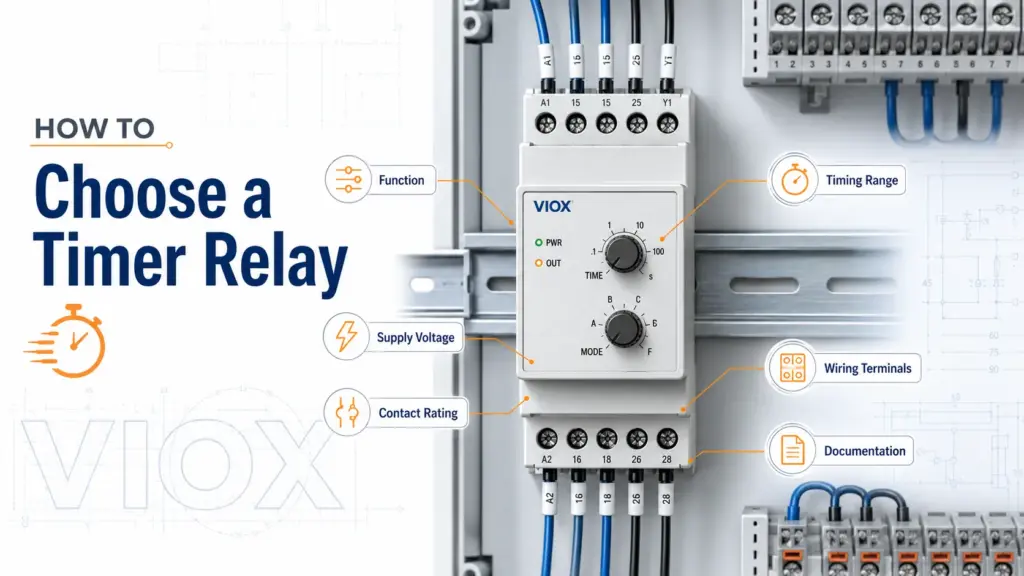
Timer Relay Wiring and Terminal Identification
Use the wiring diagram printed on the exact relay or supplied datasheet. Terminal assignments vary by function, output count and NPN/PNP control option.
| Terminal | Description |
|---|---|
| A1 | Supply line or DC positive, according to model |
| A2 | Supply neutral or DC negative, according to model |
| S / B1 | External control or trigger input on applicable models |
| 15 | Common contact for one changeover output |
| 16 | Normally closed contact |
| 18 | Normally open contact |
Connection Sequence
- Confirm the nameplate.Check supply voltage, AC/DC type, timing function and output configuration before wiring.
- Connect the supply.Wire A1 and A2 using the terminal diagram for the selected article number.
- Connect the trigger when required.Control-signal models may use S or B1 and may require a defined NPN or PNP input arrangement.
- Wire the output contact.Use COM, NO and NC contacts to switch the contactor coil, PLC input, indicator or other control load.
- Set and test the function.Select the mode, range and time value, then verify operation under the actual control sequence.
⎯⎯ Specification Matrix
FCT18 Timer Relay Selection Parameters
| Model / Family | Primary Function | Control Input | Supply Options | Output | Typical Selection Use |
|---|---|---|---|---|---|
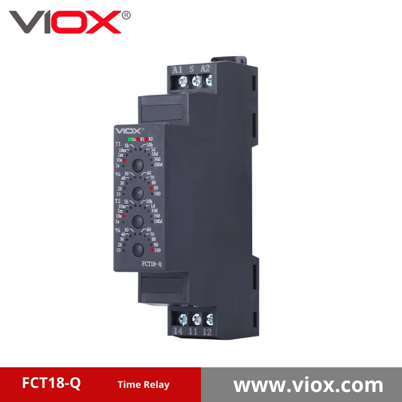
| FCT18-Q | Single-function timing | Model dependent | Confirm article number | Confirm contact arrangement | Simple control sequence requiring one defined timing mode |
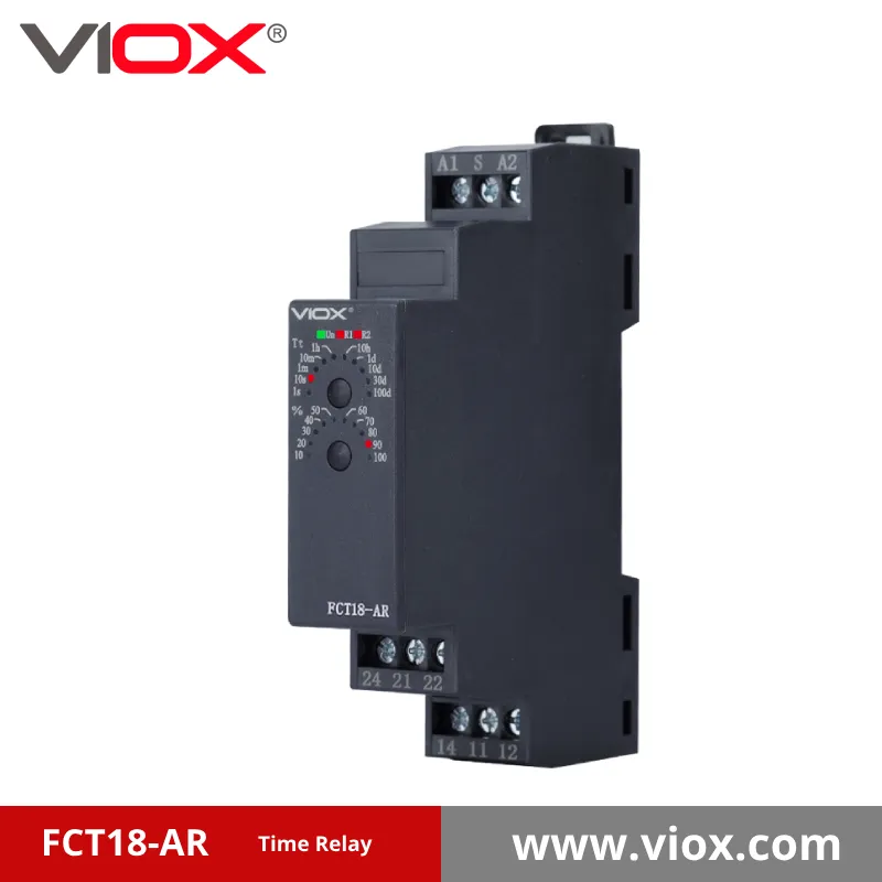
| FCT18-AR | Pulse-delayed timing | Control signal | Confirm article number | Confirm contact arrangement | Trigger-based automation and pulse timing |
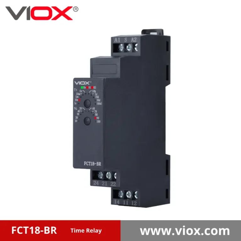
| FCT18-BR | Single interval family | NPN/PNP options by article | 12-240V AC/DC options | 1 or 2 changeover options | Timed output window after a defined trigger event |
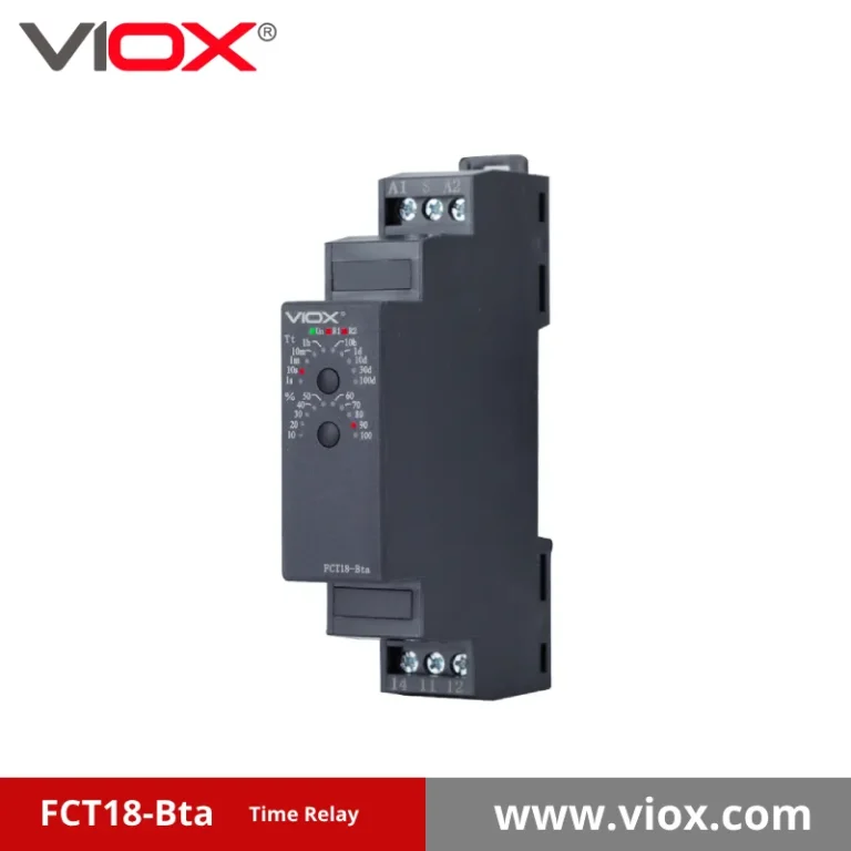
| FCT18-Bta | Off-delay with summation/control | Control signal | Confirm article number | Confirm contact arrangement | Fan run-on, delayed release and controlled stop logic |
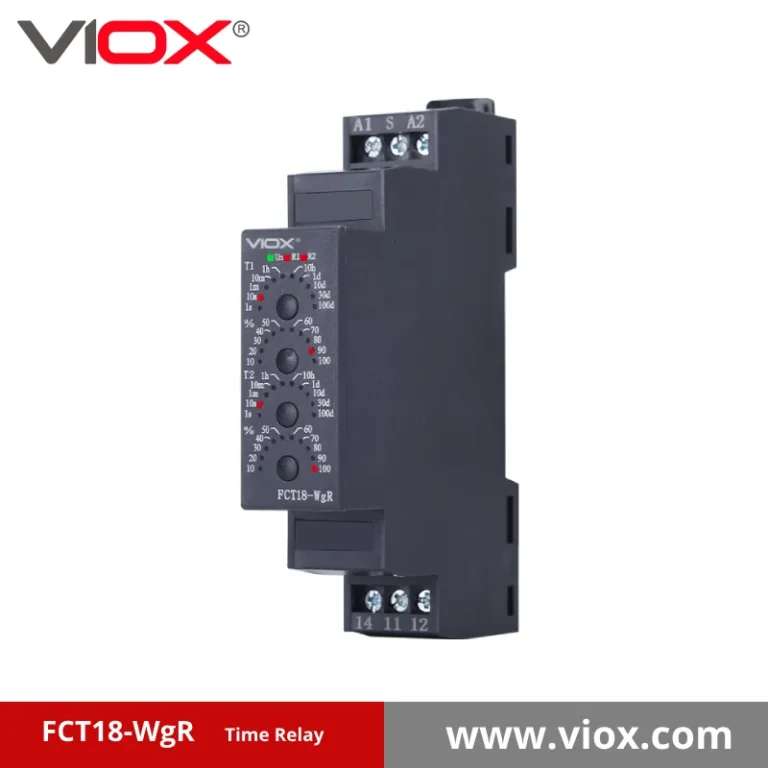
| FCT18-WgR | Asymmetrical on/off delay | Control signal | Confirm article number | Confirm contact arrangement | Independent energizing and release timing |
| FCT18-BD | Double interval | Control signal | Confirm article number | Confirm contact arrangement | Two-stage interval and sequenced timing |
| FCT18-M / N / X | Multifunction timing | Depends on selected mode | Confirm article number | Confirm contact arrangement | Panels that need several selectable timing functions |
⎯⎯ Selection
How to Choose the Right Time Relay
Project Details That Matter Most
- Required timing function: on-delay, off-delay, interval, pulse, flashing, bistable, or multifunction
- Control voltage and whether AC, DC, or both are needed
- Output load type and approximate current
- Control signal method and sequence logic
- DIN rail space and cabinet environment
- Quantity and repeat order expectation
Why This Matters for Faster RFQ
- Reduces back-and-forth over function mismatch
- Helps separate timer relay products from other relay categories
- Improves model confirmation for export panel projects
- Makes time relay quotation more accurate from the first reply
- Supports product substitution when a like-for-like function match is needed
⎯⎯ Resources
Useful Paths Around the Timer Relay Range
Extended Timer Relay Range
- FCT18-A/At
- FCT18-B/Bt
- FCT18-M / N / X
- FCT18-2T / S / P / RL / ST
Related Relay Categories
- Voltage relay
- Phase monitoring relay
- Current relay
- Floatless relay
Control Panel Use Notes
- DIN rail control cabinets
- Motor auxiliary timing
- Warning and signal output logic
- Automation sequence timing
⎯⎯ FAQ
Frequently Asked Questions About Timer Relay
What is the difference between a timer relay and a time relay?
In practice, timer relay and time relay are often used to mean the same product category. Both describe a relay that changes contact state after a preset timing function such as delay-on, delay-off, interval, or pulse timing.
What timer relay functions are most common in the VIOX range?
The most common functions include single-function time relay, on-delay, off-delay, interval, pulse-delayed, asymmetrical flashing, bistable, and asymmetrical on-delay and off-delay timing. The FCT18 range is organized around these practical control logic types.
What voltage range is available for VIOX timer relay products?
VIOX timer relay products support wide AC/DC control voltage coverage from 12V to 240V, which helps the same product family fit different control panel standards and retrofit requirements.
How do I choose the right timer relay model?
Start with the actual timing function, then confirm supply voltage, output contact rating, control signal method, timing range, and application environment. This narrows the model faster than starting from dimensions or general category names.
What details should I send for a timer relay quotation?
Send the preferred timer relay function, control voltage, contact rating, installation format, application, and quantity. If you already know a target model such as FCT18-Q, FCT18-Bta, or FCT18-WgR, include it in the RFQ to speed up confirmation.
⎯⎯ Request Quote
Discuss the Right Timer Relay Configuration
- Required timer relay function
- Supply voltage and control method
- Output contact load and current
- Preferred model or equivalent reference
- Installation environment and panel format
- Trial quantity and repeat order expectation