On this page
A DIN rail is a standardized metal mounting profile used to support compatible electrical and control components inside panels and enclosures. IEC 60715 covers dimensional and functional requirements for several rail profiles, but matching the rail width alone does not prove that a device, busbar, enclosure, or complete assembly is compatible.
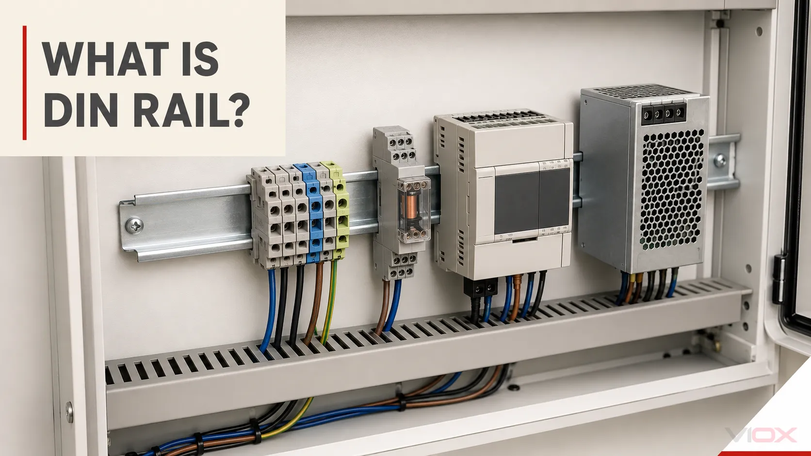
The rail is the mechanical interface at the back of the assembly. Circuit breakers, terminal blocks, relays, contactors, power supplies, controllers, and other devices attach to it with clips or clamps designed for a particular profile. The device instructions, rail data, enclosure design, and applicable assembly requirements still control the finished installation.
DIN Rail at a Glance
| If you need to… | Start with… | What the answer should produce |
|---|---|---|
| Identify an unfamiliar rail | Profile shape and nominal dimensions | A likely TH, G, or C profile to verify against a drawing |
| Check a device fit | The device manufacturer’s permitted rail profile | Confirmed mounting compatibility—not an assumption based on width |
| Choose a rail for a new panel | Component, load, environment, span, material, and fastening inputs | A rail specification for the panel design |
| Decide between rail and direct mounting | Service, load, vibration, space, cooling, and device constraints | A mounting-method decision |
| Install or modify a rail | Rail, enclosure, and device instructions | A controlled mounting and inspection procedure |
| Source DIN rail | Profile drawing, material, finish, length, slots, quantity, and packing | Comparable product records or an RFQ |
For a new design, move from this overview to the DIN rail selection guide. If the basic mounting method is still undecided, compare DIN rail and direct panel mounting.
What Does “DIN” Mean?
DIN is the abbreviation used by DIN Deutsches Institut für Normung, the German Institute for Standardization. In “DIN rail,” the term reflects the mounting-rail standards and designations that originated in Germany and were later incorporated into European and international standardization.
Calling a product “DIN-rail mounted” does not mean that DIN has certified the product. It normally describes the mechanical mounting interface. Any certification, listing, electrical rating, environmental rating, or market approval must be verified separately for the exact product.
You may encounter several names for the common 35 mm symmetrical profile:
- Top Hat rail describes its cross-sectional shape.
- TH35 is the designation used in IEC-oriented documentation.
- TS35 is widely used in manufacturer catalogs and legacy references.
- 35 mm DIN rail or DIN 35 rail is common commercial shorthand.
These names often point to the same profile family, but the complete designation matters. A TH35 rail can have different heights, material thicknesses, hole patterns, finishes, and lengths.
Main DIN Rail Types and Nominal Sizes
The profile shape is the first compatibility check. The table below is an identification guide, not a substitute for the current standard, the rail drawing, or the mounted-device instructions.
| Profile family | Common designation | Nominal cross-section | Typical recognition cue | Important boundary |
|---|---|---|---|---|
| Symmetrical Top Hat | TH35, often sold as TS35 | 35 × 7.5 mm | Shallow, symmetrical hat shape | The most common general-purpose profile, but device and assembly compatibility still require verification |
| Deep symmetrical Top Hat | TH35, often sold as TS35 | 35 × 15 mm | Same 35 mm width with a deeper section | The deeper profile changes stiffness and mounting geometry; do not assume it is required solely from device weight |
| Miniature Top Hat | TH15, often sold as TS15 | 15 × 5.5 mm nominal family | Narrow symmetrical profile | Used only with components designed for the smaller profile |
| G section | G32 | 32 × 15 mm nominal family | Asymmetrical hooked profile | Common in legacy or specialized equipment; a TH35 clip is not automatically compatible |
| C section | C-profile mounting rail | Multiple standardized sizes | Channel-like cross-section | Used with compatible clamps, supports, and selected devices; verify the exact C profile |
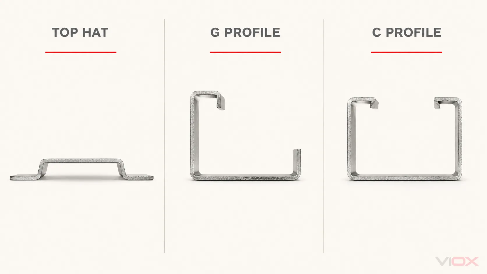
Manufacturers may use catalog names that combine the family with height, thickness, slot pattern, or material. Read the drawing rather than relying on a shortened label. Exact tolerances also belong to the applicable standard or product drawing and should not be inferred from nominal dimensions.
Rail Size Is Not Module Width
A 35 mm rail is 35 mm across its profile; it does not mean that every mounted device is 35 mm wide. Modular distribution devices are often described using a module width near 17.5 or 18 mm, while industrial relays, controllers, power supplies, and terminal blocks use many other widths.
Rail profile, device width, enclosure opening, busbar pitch, and adjacent accessory geometry are separate checks.
What IEC 60715 Covers
IEC 60715:2017 is titled Dimensions of low-voltage switchgear and controlgear—Standardized mounting on rails for mechanical support of switchgear, controlgear and accessories. It establishes dimensional and functional requirements for compatible mounting on certain rail types.
That scope is narrower than many “universal DIN rail” claims suggest.
| IEC 60715 helps define | IEC 60715 alone does not prove |
|---|---|
| Standardized mounting-rail profiles and dimensions within its scope | That every DIN-rail device fits every rail marketed with a similar name |
| Functional requirements for compatible mechanical mounting | Electrical ratings, interrupting capacity, insulation coordination, or environmental performance |
| A common mechanical reference for device and rail designers | Compatibility with a particular enclosure, busbar, terminal system, or accessory family |
| Rail geometry used in switchgear and controlgear installations | That the rail is an approved protective conductor or current-carrying busbar in a given assembly |
The 2017 edition explicitly leaves the rail’s protective-earthing electrical function to the relevant product standard. A metallic rail may participate in a protective-bonding arrangement only when the applicable equipment, terminal, rail, enclosure, and assembly requirements support that use. It must not be treated as a phase or neutral conductor merely because it is conductive.
Why a Correct Rail Profile Does Not Guarantee Compatibility
DIN rail standardization simplifies mechanical integration, but the complete fit has several layers.
- Profile fit: The device clip or clamp must match the rail family and permitted height.
- Mechanical capacity: Rail material, thickness, span, fasteners, mounted mass, shock, and vibration affect stiffness and retention.
- Device orientation: Some products permit only specified mounting positions or require accessories in particular orientations.
- Thermal clearance: Spacing can depend on the exact device, ambient temperature, duty, neighboring equipment, and enclosure conditions.
- Electrical interfaces: Busbars, terminals, conductors, accessories, and protective bonding have their own compatibility rules.
- Assembly requirements: The enclosure or switchgear assembly may restrict component combinations, mounting methods, or modifications.
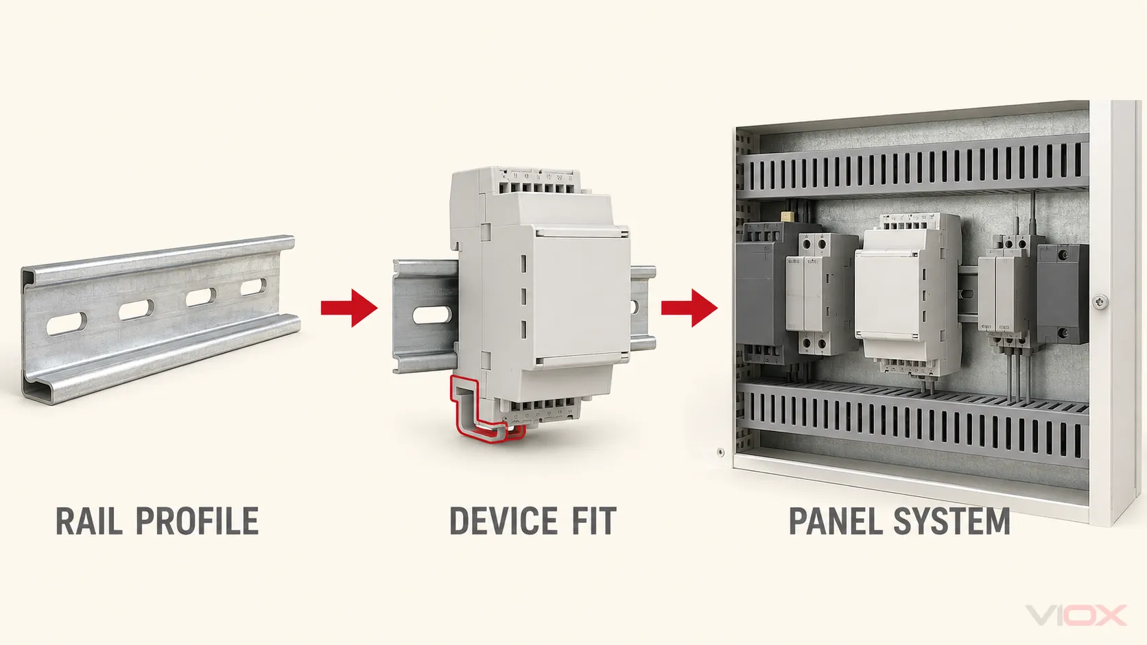
For example, a manufacturer may permit a device on both TH35 × 7.5 mm and TH35 × 15 mm rails while separately defining minimum clearances and mounting positions. Another device with a visually similar clip may allow only one profile or orientation. The product documentation is therefore the final fit check.
Materials and Surface Finishes
DIN rails are commonly supplied in steel, stainless steel, and aluminum variants. Material alone does not determine suitability; the complete material grade, coating or finish, rail geometry, thickness, environment, fasteners, and bonding design matter.
| Material route | Why it may be considered | What still needs verification |
|---|---|---|
| Coated or plated steel | Stiffness, broad availability, economical panel construction | Material grade, coating system, cut-edge treatment, corrosion exposure, and bonding requirements |
| Stainless steel | Corrosive or hygienic environments where the selected grade is appropriate | Exact grade, surface condition, fasteners, galvanic interfaces, and environmental compatibility |
| Aluminum | Lower mass, machinability, or nonmagnetic design needs | Alloy, temper, stiffness, finish, galvanic interfaces, and protective-bonding design |
Use the detailed aluminum versus steel DIN rail comparison when material choice is the actual decision. For supplier or incoming inspection, use the DIN rail quality checklist rather than judging a rail only by color or apparent thickness.
What Mounts on a DIN Rail?
Common DIN-rail-mounted equipment includes:
- terminal blocks and protective-conductor terminals;
- miniature circuit breakers and other modular protective devices;
- interface relays, monitoring relays, and timer relays;
- contactors and motor-control accessories designed for rail mounting;
- power supplies, signal conditioners, and industrial communication modules;
- programmable logic controllers, remote I/O, and control modules;
- energy meters, transducers, and selected panel accessories.
The list describes common product families, not interchangeability. A device can be designed for DIN-rail mounting and still be unsuitable for a particular rail, panel, busbar system, voltage, environment, or assembly.
Where DIN Rails Fit in a Panel
DIN rails create repeatable mounting rows inside distribution boards, control cabinets, machine panels, automation enclosures, and equipment boxes. They make it easier to organize compatible components and modify a layout without drilling a dedicated hole pattern for every device.
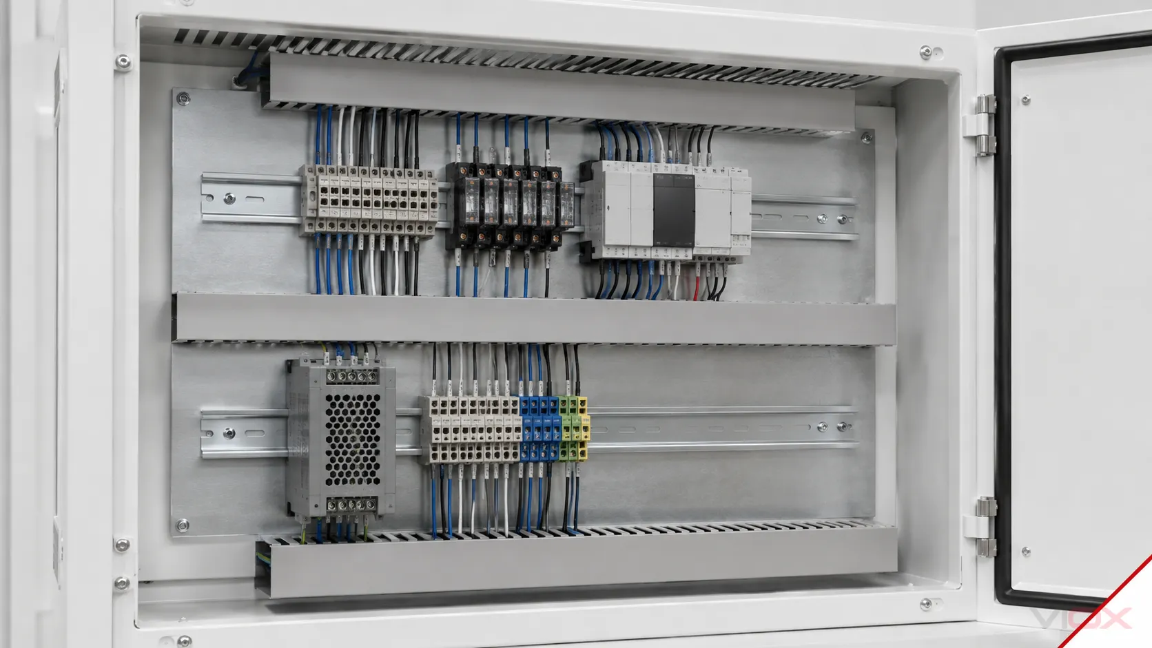
The rail does not determine the complete panel layout. Wire ducts, conductor bend space, heat-producing equipment, electromagnetic disturbance sources, service access, segregation, enclosure clearances, and future expansion must be resolved at the assembly level. Those values should come from the applicable design rules and the instructions for the actual equipment—not from a universal DIN rail spacing number.
Installation: The Safe Boundary for a General Guide
A typical rail-mounted device hooks onto one edge of its permitted profile and then snaps or clamps onto the other edge. Removal often uses a device latch and a tool specified by the manufacturer. That basic motion does not replace the full installation procedure.
Before mounting or modifying a rail assembly, verify:
- the rail profile and drawing;
- enclosure and backplate requirements;
- rail material, thickness, span, and fasteners;
- device mounting position and clearances;
- end stops or other restraints required by the device row and environment;
- protective-bonding provisions where applicable;
- cut edges, burrs, debris, and finish damage;
- final retention, alignment, wiring access, and inspection requirements.
Follow the rail, enclosure, and mounted-device instructions. De-energization, safe isolation, and local electrical-work requirements remain essential. For the cutting subtask, see how to use a DIN rail cutter.
Choose the Right Next Resource
This page identifies the system. The next page should match the decision you actually need to make.
| Your next question | Recommended VIOX resource |
|---|---|
| Should I use DIN rail or mount the device directly? | DIN Rail vs. Traditional Mounting |
| Which profile, material, height, and hole pattern should I specify? | How to Choose the Right DIN Rail |
| Why is the 35 mm Top Hat profile so common? | Why TH35 Became the Industry Standard |
| Should I use aluminum or steel? | Aluminum vs. Steel DIN Rails |
| How do I evaluate rail or supplier quality? | How to Determine DIN Rail Quality |
| What changes a DIN rail quotation? | DIN Rail Price Factors |
| Which suppliers should I evaluate? | DIN Rail Manufacturers and Suppliers |
| Which VIOX rail series are published? | VIOX DIN Rail Product Range |
| I need cut lengths, slot review, packing, or OEM supply | VIOX DIN Rail Manufacturer and OEM Supply |
When evaluating a product, start with the exact mounted devices and required profile, then compare the published rail drawing, material, height, thickness, length, hole pattern, finish, and installation constraints. A catalog label such as “35 mm DIN rail” is a starting point, not a completed specification.