On this page
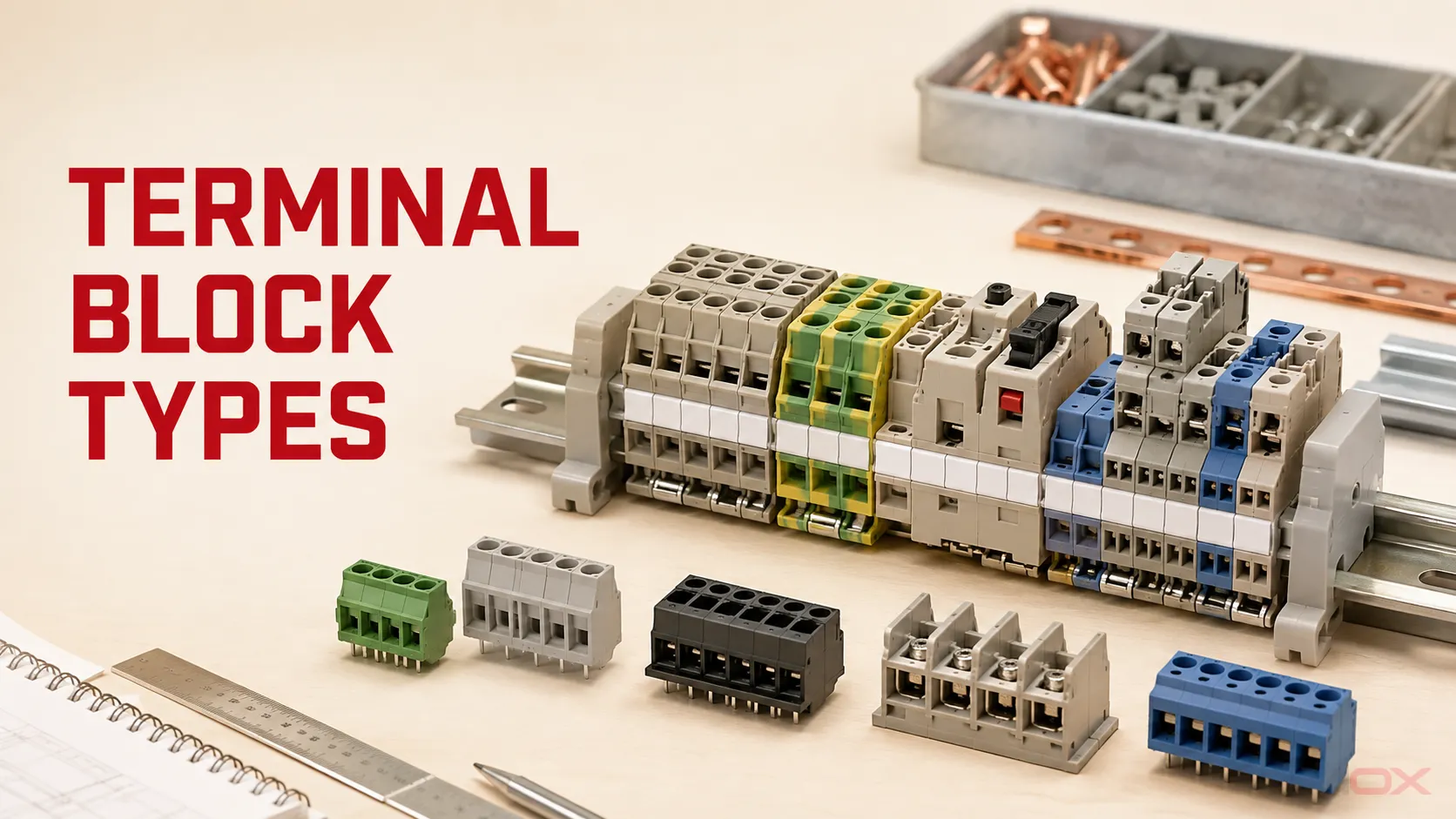
A terminal block is an insulated connection device used to terminate, join, distribute, ground, isolate, or test electrical conductors. Terminal blocks can be classified by function, connection method, mounting format, and circuit duty. These labels describe different design questions, so a product may be a DIN-rail, feed-through, push-in terminal block at the same time.
Use this guide to build a correct map of the main terminal block types, then follow the links to a focused selection, comparison, standards, or troubleshooting resource.
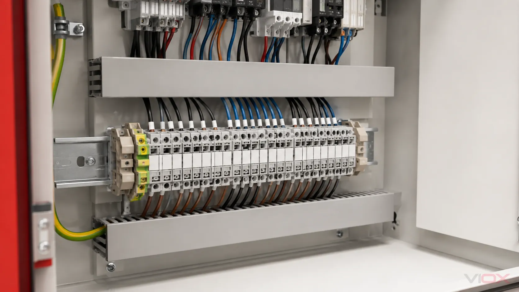
The Four Ways Terminal Blocks Are Classified
Many terminal block guides mix unlike categories. “DIN rail” describes mounting. “Feed-through” describes circuit function. “Push-in” describes the conductor connection. “Power” or “signal” describes electrical duty. Separating those axes makes product identification and specification much clearer.
| Classification axis | Typical categories | The question it answers |
|---|---|---|
| Function | Feed-through, protective earth, fuse, disconnect/test, multi-level, distribution | What does the terminal do in the circuit? |
| Connection method | Screw, spring-clamp, push-in, stud/bolt | How is the conductor retained? |
| Mounting format | DIN rail, PCB, panel/barrier, pluggable interface | Where and how is it installed? |
| Circuit duty | Signal, control, power, grounding, measurement | What electrical and service conditions must it support? |
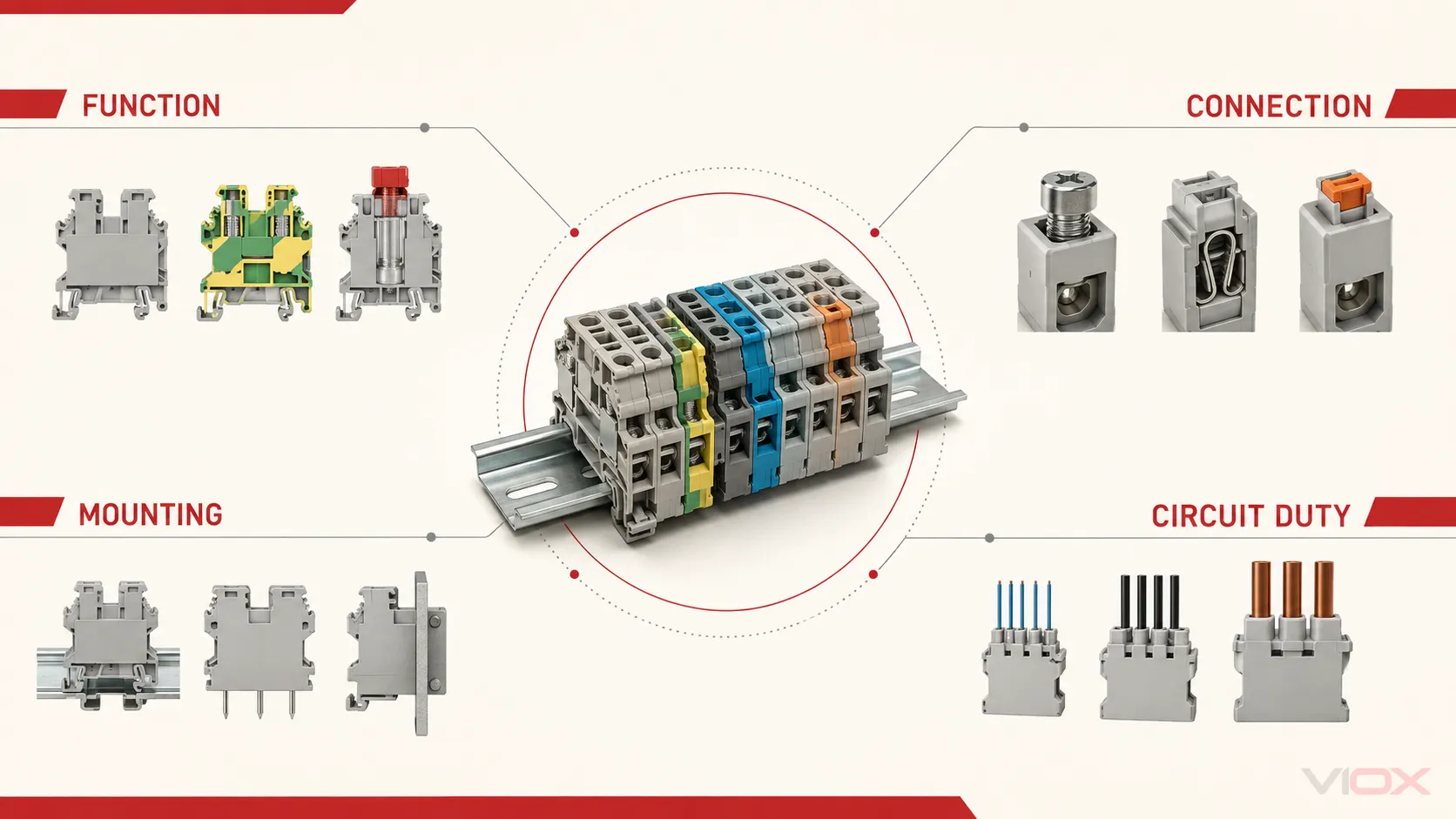
This four-axis map is the fastest way to interpret a catalog description. For example, “spring-clamp PE terminal for 35 mm DIN rail” identifies the connection method, safety function, and mounting format, while the exact conductor and electrical ratings still come from that product’s data.
Terminal Block Types by Function
Function should usually be the first classification decision because it defines the terminal’s job in the circuit.
Feed-Through Terminal Blocks
A feed-through terminal provides a conductive path between its connection points. In an industrial control panel, it commonly forms the serviceable boundary between field wiring and internal wiring. The block can be marked, tested, and replaced without turning the connection into a permanent splice.
Feed-through describes function, not connection technology. Screw, spring-clamp, and push-in designs can all perform the same feed-through role.
Protective-Earth Terminal Blocks
A protective-earth (PE) terminal connects a protective conductor to the intended grounding path, often through a conductive connection to the mounting rail. It is a safety component, not simply a green-and-yellow version of a normal feed-through terminal.
Use only a terminal designed and documented for the PE function. The rail, end supports, enclosure bonding, conductor, and installation requirements remain part of the complete protective-conductor system.
Fuse Terminal Blocks
A fuse terminal combines a termination point with a replaceable fuse interface. It can simplify branch or control-circuit protection and make an individual protected circuit easier to identify. The accepted fuse format, indicator circuit if present, dissipation limits, conductor data, and terminal ratings are product-specific.
A fuse terminal does not replace the need to evaluate the complete protective-device arrangement. For general fuse-holder architecture, see the complete guide to fuse holders.
Disconnect and Test Terminal Blocks
Disconnect and test terminals provide an intentional point for isolation, measurement, or commissioning without removing the connected conductors. Designs include knife-disconnect, plug-disconnect, and dedicated test arrangements.
The important distinction is functional: opening a test terminal may isolate a measurement path, but it should not automatically be treated as a load-break disconnect or protective device. Use the exact product instructions and circuit documentation for the intended operation.
Multi-Level Terminal Blocks
Multi-level terminals stack separate connection levels within one terminal-body width. They help organize dense sensor, control, or marshalling circuits where rail length is limited. Some families group supply, signal, and return functions; others provide repeated feed-through levels.
Space savings should be considered together with marking visibility, wire bend space, test access, jumper arrangement, and heat from adjacent circuits.
Power Distribution Blocks and Distribution Modules
A power distribution block typically accepts one or more incoming conductors and provides multiple outgoing connection points. It serves feeder-to-branch distribution rather than simple point-to-point marshalling. A terminal block distribution module may provide a more structured common-potential arrangement for control wiring.
When the design decision is between a terminal row and a higher-current distribution architecture, use the dedicated bus bars vs terminal blocks guide.
Terminal Block Types by Connection Method
The connection method affects conductor preparation, installation process, inspection, servicing, and suitability for mechanical conditions. It does not establish a universal current range or make one technology best for every application.
| Connection method | How it retains the conductor | Evaluate before choosing |
|---|---|---|
| Screw | A screw-driven clamp or pressure element establishes contact | Specified torque, conductor preparation, access, and product instructions |
| Spring-clamp | A spring element maintains contact force | Opening method, conductor range, preparation, vibration environment, and service access |
| Push-in | Supported conductors are inserted directly into a spring contact | Eligible conductor types, ferrule requirements, release method, and insertion verification |
| Stud/bolt | A nut and stud clamp a compatible lug or conductor interface | Lug material and hole size, hardware stack, torque, covers, and clearance |
Ferrule requirements cannot be generalized by technology name alone. A particular terminal may accept solid, stranded, fine-stranded, or ferruled conductors in different ranges. Confirm the conductor table and preparation instructions for the exact part number.
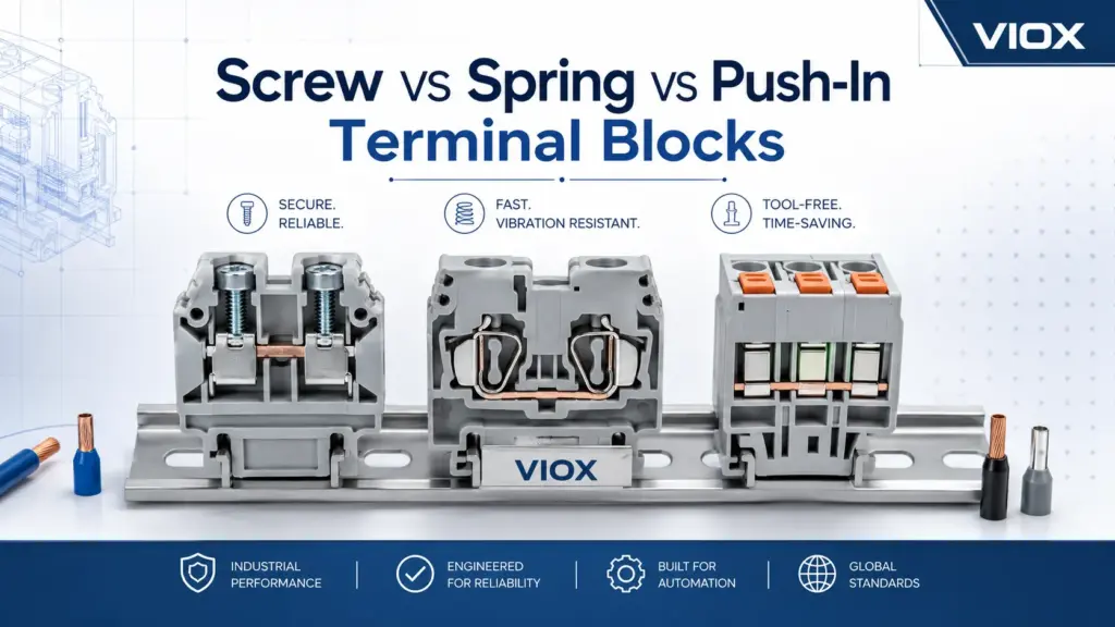
For a decision-level comparison, read Screw vs Spring vs Push-In Terminal Blocks.
Terminal Block Types by Mounting Format
DIN-Rail Terminal Blocks
DIN-rail terminals are modular devices fixed to a compatible support rail and assembled into a terminal row with end supports, markers, partitions, and jumpers where required. They are common in industrial panels because circuits can be grouped and serviced position by position.
DIN-rail compatibility does not guarantee that accessories from different product families are interchangeable. Terminal width, end plates, bridges, test plugs, marking systems, and spacing provisions must be checked as a system. Use the focused guide on how to select DIN-rail mounted terminal blocks when the rail assembly is already known.
PCB Terminal Blocks
Printed circuit board (PCB) terminal blocks connect field conductors to a board. Their specification includes board footprint, pitch, orientation, solder or mounting interface, conductor entry, and mechanical loads in addition to electrical ratings.
Pitch is especially important because it must match the board layout and affects available spacing. The terminal block pitch guide explains how to read this dimension without treating pitch as a current rating.
Barrier and Panel-Mounted Terminal Blocks
Barrier terminal strips use insulating walls between adjacent positions and are normally fixed to a panel, chassis, or equipment base. They can support clear visual separation and ring- or fork-lug arrangements when the product is designed for them.
“Terminal strip” is sometimes used broadly, so mounting style and construction should be confirmed rather than inferred from the name. See Terminal Strip vs Terminal Block for the terminology and selection boundary.
Pluggable Terminal Interfaces
A pluggable terminal arrangement separates the field-wire termination from a mating header or base. It can help modular assembly or replacement, but the plug, header, coding, pitch, current path, and locking arrangement must be treated as a matched system.
The Key Ratings and Data to Recognize
A hub cannot safely turn terminal block selection into a universal size chart. The useful first step is knowing which data must be verified on the exact terminal family and application.
| Data field | What it controls | Common mistake |
|---|---|---|
| Terminal function | Feed-through, PE, fuse, disconnect, test, or distribution role | Choosing by appearance rather than circuit duty |
| Rated voltage and insulation data | Suitability for the stated electrical and environmental conditions | Treating one printed voltage as the complete insulation decision |
| Rated current and thermal data | Current carrying performance under stated conditions | Ignoring conductor, grouping, jumper, or enclosure conditions |
| Conductor range | Accepted cross-section and conductor construction | Assuming physical fit proves approval |
| Strip length and preparation | Correct placement inside the clamping zone | Clamping insulation or leaving exposed conductor |
| Ferrule information | Whether and how a ferrule is accepted | Applying a universal ferrule rule |
| Pitch and terminal width | PCB fit, spacing, rail density, and access | Treating pitch as an electrical rating |
| Environmental data | Temperature, contamination, corrosion, and other declared limits | Substituting a generic material claim for product evidence |
| Accessories | Jumper, end plate, separator, marker, test plug, and end-stop compatibility | Mixing visually similar product families |
| Approvals and documentation | Evidence required for the product and target market | Treating a component approval as approval of the assembled panel |
IEC 60947-7-1:2025 covers specified terminal blocks and test-disconnect terminal blocks with screw-type or screwless clamping units for industrial or similar use within its published scope. UL Solutions identifies UL 1059 in the North American terminal-block certification context. Neither reference makes every product suitable for every circuit or completed assembly. Confirm the exact product documentation and the requirements that govern the equipment in its destination market.
Use the Terminal Block Selection Guide when you are ready to convert circuit, conductor, environmental, and documentation inputs into a purchasing specification. For approval pitfalls, see Terminal Block Certifications: 5 Mistakes to Avoid.
How Terminal Blocks Appear in a Panel Wiring Diagram
A terminal block diagram normally represents the terminal as a documented connection point between field conductors and internal panel circuits. The drawing should identify terminal designations and connection relationships; it is not a substitute for the product’s installation instructions.
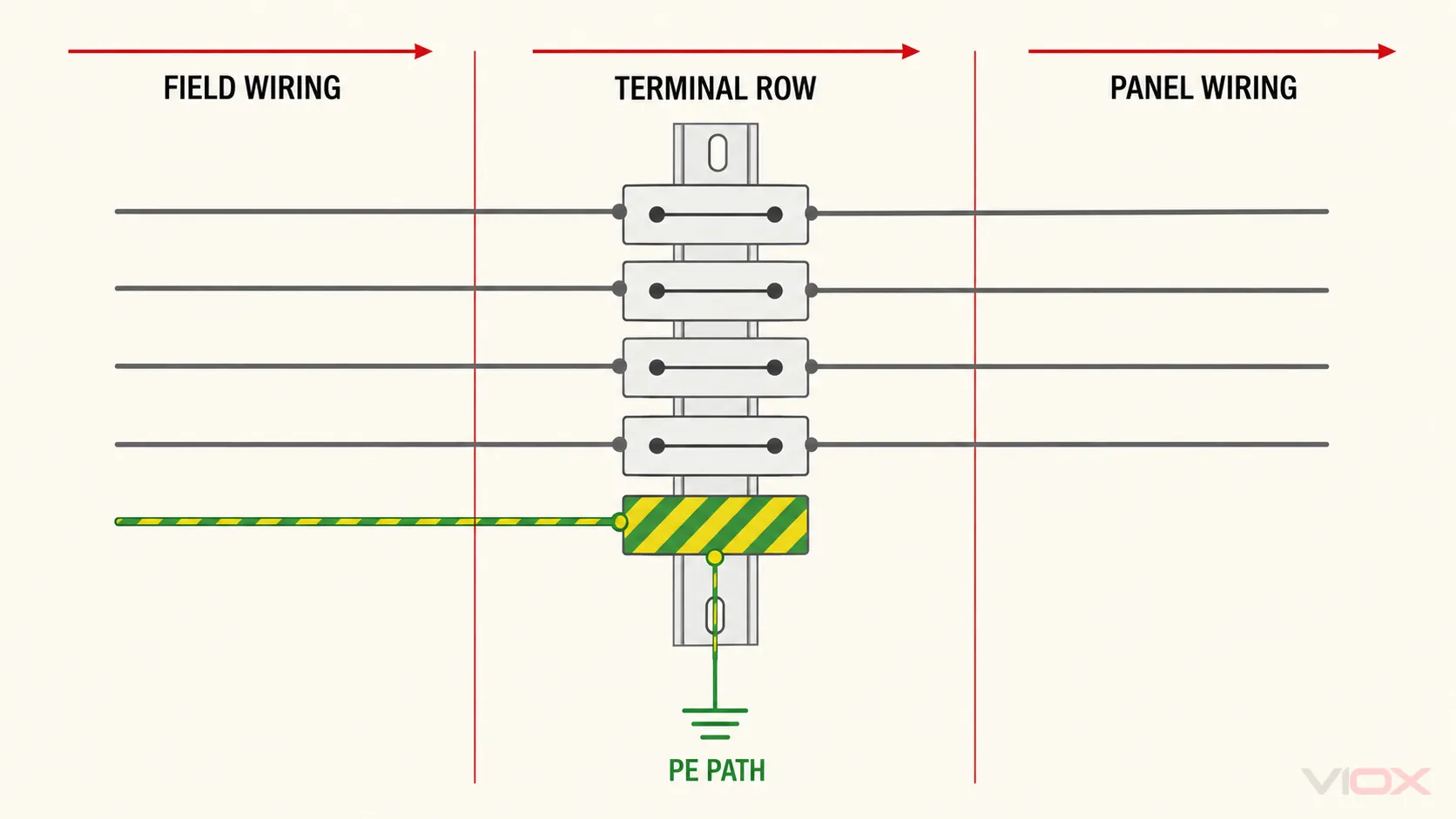
In the conceptual diagram above, the terminal row creates an organized interface between field devices and internal control equipment. A PE terminal belongs to the protective-conductor path, while feed-through terminals carry their documented circuit connections. Jumpers, disconnect elements, and fused paths should appear only where the actual design includes them.
Before installation or modification, use the approved project drawing, terminal plan, conductor schedule, and exact component instructions. Do not infer a real wiring connection from a generic illustration.
Where Different Terminal Block Families Fit
| Application | Typical priorities | Useful next resource |
|---|---|---|
| Industrial control panel | Field/internal boundary, marking, test access, rail layout, accessories | DIN-rail terminal block selection |
| Machinery with vibration | Connection technology, conductor preparation, service access, documented mechanical suitability | Screw vs spring vs push-in |
| Dense PLC or sensor wiring | Multi-level layout, marking, shielding/grounding plan, test access | Terminal block components |
| High-temperature equipment | Housing and insulation system, conductor temperature class, spacing, mounting environment | Ceramic terminal blocks explained |
| Marine or corrosive environment | Declared environmental suitability, material system, enclosure, vibration, maintenance | Marine terminal block guide |
| Feeder distribution | Conductor capacity, touch protection, spacing, thermal performance, branch architecture | Bus bars vs terminal blocks |
| Existing hot or discolored connection | Isolation, inspection, conductor condition, contact resistance, loading, replacement decision | Terminal block overheating diagnosis |
Choose the Next Terminal Block Resource
- To specify a product from circuit and conductor inputs, use the complete terminal block selection guide.
- To compare conductor connection technologies, use Screw vs Spring vs Push-In Terminal Blocks.
- To understand the housing, current bar, clamp, insulation, and accessories, open Terminal Block Components.
- To evaluate board spacing or compact terminal geometry, open Terminal Block Pitch Explained.
- To diagnose a thermal symptom, use the terminal block overheating guide.
For product matching, review the VIOX terminal block range or send the circuit voltage, current, conductor size and type, required function, mounting format, environment, and approval requirements to [email protected]. Product selection should be confirmed against the exact VIOX datasheet and the requirements of the finished equipment.