Understanding Electrical Derating: Why It Matters for Safe Installations
Electrical derating is the systematic reduction of a conductor’s current-carrying capacity (ampacity) to account for real-world installation conditions that deviate from standard testing environments. When cables operate in high temperatures, at elevated altitudes, or bundled with other conductors, their ability to dissipate heat diminishes significantly. Without proper derating calculations, installations face serious risks: premature insulation failure, circuit breaker nuisance tripping, fire hazards, and non-compliance with NEC Article 310.15 and IEC 60364-5-52 standards.
For B2B professionals installing EV charging infrastructure, solar arrays, or industrial electrical systems, understanding derating factors isn’t optional—it’s a fundamental requirement for safety, code compliance, and system longevity. This master guide provides the technical framework you need to calculate accurate derating factors and size conductors correctly for any installation scenario.
Section 1: Temperature Derating Factors
Ambient Air Temperature Correction
Standard reference conditions assume an ambient temperature of 30°C (86°F) for cables installed in air. When actual temperatures exceed this baseline, conductor ampacity must be reduced according to NEC Table 310.15(B)(1) or IEC 60364-5-52 Table B.52.14.
Critical temperature derating factors for common insulation types:
| Ambient Temperature | PVC Insulation (70°C) | XLPE/EPR Insulation (90°C) |
|---|---|---|
| 30°C (86°F) | 1.00 | 1.00 |
| 35°C (95°F) | 0.94 | 0.96 |
| 40°C (104°F) | 0.87 | 0.91 |
| 45°C (113°F) | 0.79 | 0.87 |
| 50°C (122°F) | 0.71 | 0.82 |
| 55°C (131°F) | 0.61 | 0.76 |
Real-world application: Solar installations on commercial rooftops routinely experience 50-55°C ambient temperatures in summer. A 10 AWG copper THHN conductor rated for 40A at 30°C drops to just 32.8A (40A × 0.82) at 50°C—a 18% reduction that could overload undersized conductors.
Soil Temperature Correction for Underground Cables
Underground installations face different thermal challenges. IEC 60287 and NEC standards reference 20°C (68°F) soil temperature as the baseline for buried cables.
Soil temperature correction factors:
| Soil Temperature | Correction Factor (All Insulation Types) |
|---|---|
| 20°C (68°F) | 1.00 |
| 25°C (77°F) | 0.96 |
| 30°C (86°F) | 0.92 |
| 35°C (95°F) | 0.87 |
| 40°C (104°F) | 0.82 |
| 45°C (113°F) | 0.77 |
| 50°C (122°F) | 0.71 |
Buried depth also affects thermal performance. Cables buried at 80cm depth experience approximately 4% better heat dissipation than those at 50cm depth, yielding a correction factor of 0.96 that partially offsets high soil temperatures.
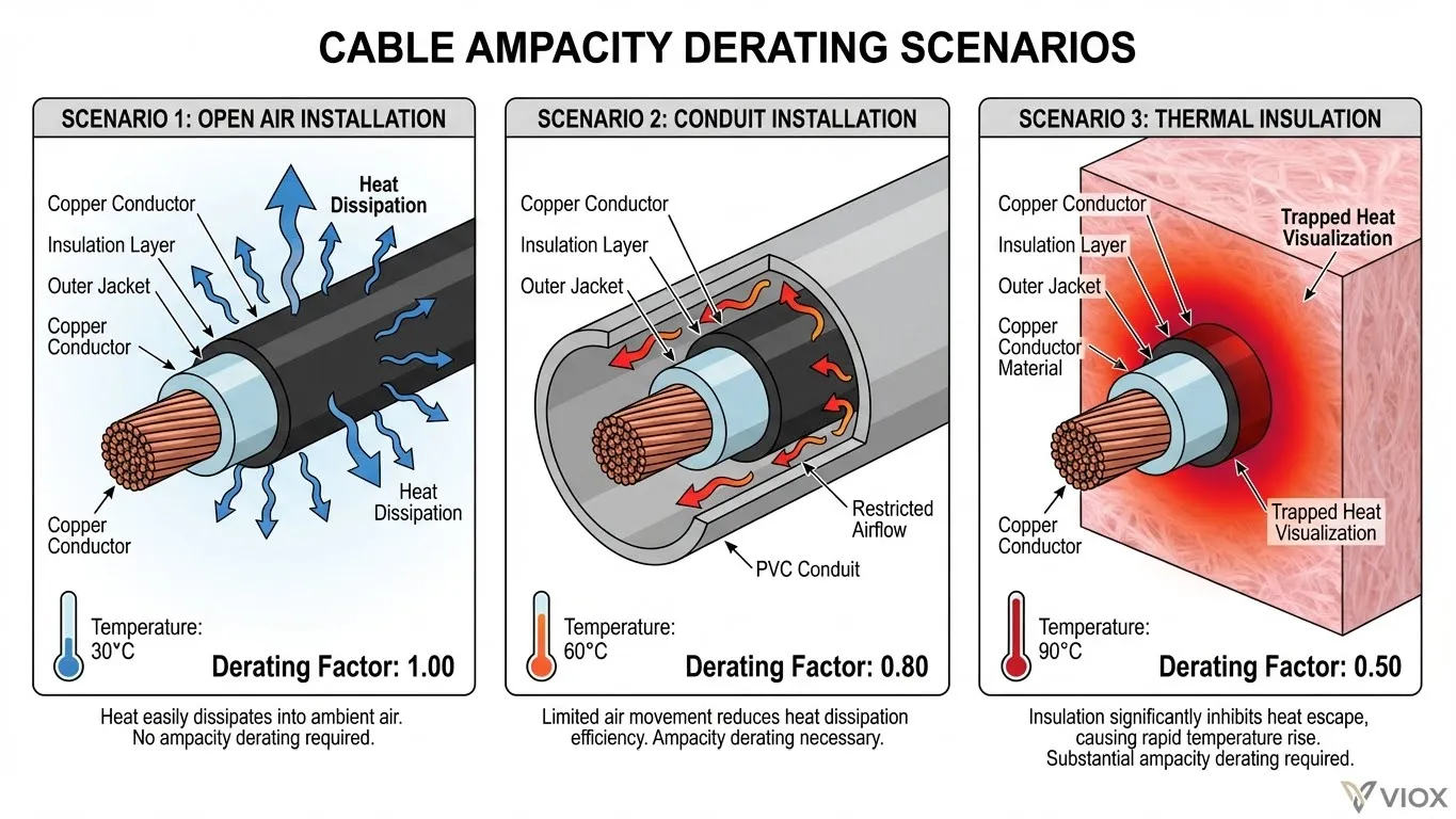
Thermal Insulation Contact Effects
When cables pass through or are surrounded by thermal insulation (common in building penetrations), heat dissipation severely degrades. Per NEC 310.15(A)(3) and IEC 60364-5-52:
- Cables touching thermal insulation for ≤100mm: Apply factor of 0.89
- Cables surrounded by insulation for >500mm: Apply factor of 0.50 (50% reduction)
- Ring final circuits in insulated spaces: May require upsizing from 2.5mm² to 4mm²
For residential and commercial circuit breaker applications, this often-overlooked factor causes significant sizing errors.
Section 2: Altitude Derating Factors
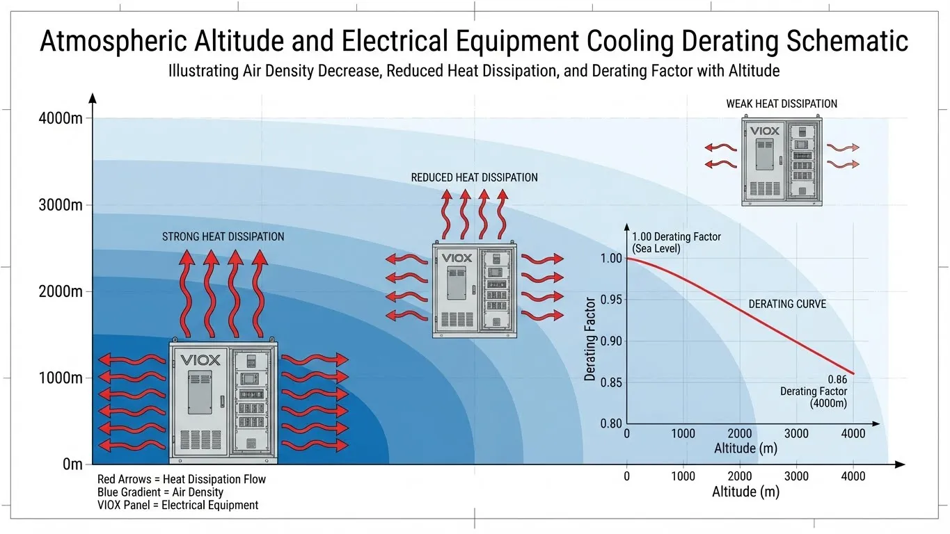
Why Altitude Affects Electrical Equipment
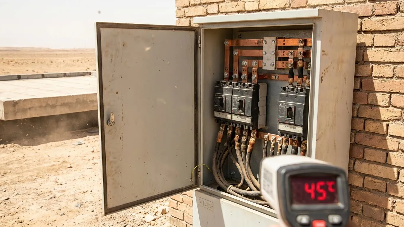
At elevations above 1,000 meters (3,300 feet), reduced atmospheric pressure diminishes air density, decreasing the cooling efficiency of electrical equipment. Heat dissipation from cable surfaces, transformers, and circuit breakers becomes less effective, requiring capacity reductions.
Altitude correction factors per IEC 60364-5-52 and manufacturer specifications:
| Altitude (meters) | Altitude (feet) | Power Derating Factor | Voltage Derating Factor |
|---|---|---|---|
| 0-1,000 | 0-3,300 | 1.00 | 1.00 |
| 1,000-1,500 | 3,300-4,900 | 0.99 | 1.00 |
| 1,500-2,000 | 4,900-6,600 | 0.97 | 0.99 |
| 2,000-3,000 | 6,600-9,800 | 0.94 | 0.98 |
| 3,000-4,000 | 9,800-13,100 | 0.90 | 0.97 |
| 4,000-5,000 | 13,100-16,400 | 0.86 | 0.95 |
Practical Implications for Mountain Installations
Case study: A 22kW EV charging station installed at 2,500 meters elevation in Colorado requires a conductor sized for 120A ÷ 0.95 = 126.3A after altitude derating. This represents a 5.3% capacity reduction compared to sea-level installations.
Equipment considerations:
- Circuit breakers may experience reduced interrupting capacity at altitude
- Transformer cooling efficiency drops approximately 1% per 100 meters above 1,000m
- Switchgear and panelboards require larger enclosures for adequate convection cooling
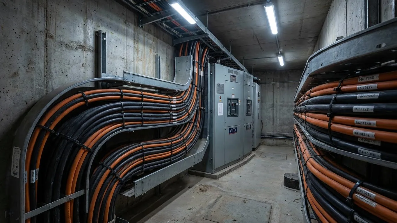
- VIOX industrial-grade circuit breakers incorporate altitude compensation ratings up to 4,000m
Note: Liquid-cooled equipment can partially compensate for altitude effects through reduced coolant temperature, but air-cooled systems require strict adherence to derating tables.
Section 3: Cable Grouping and Bundling Derating
Mutual Heating Effects in Multi-Cable Installations
When multiple current-carrying conductors share the same raceway, cable tray, or underground trench, they generate mutual heating that impairs each cable’s ability to dissipate heat. This phenomenon necessitates aggressive derating per NEC Table 310.15(C)(1) and IEC 60364-5-52.
Grouping derating factors (NEC/IEC standards):
| Number of Current-Carrying Conductors | Adjustment Factor | Effective Ampacity Loss |
|---|---|---|
| 1-3 | 1.00 | 0% |
| 4-6 | 0.80 | 20% |
| 7-9 | 0.70 | 30% |
| 10-20 | 0.50 | 50% |
| 21-30 | 0.45 | 55% |
| 31-40 | 0.40 | 60% |
| 41+ | 0.35 | 65% |
Critical considerations:
- Neutral conductors carrying harmonic currents count as current-carrying conductors
- Grounding/bonding conductors do not count toward grouping derating
- Cables operating at <35% of their grouped rating can be excluded from the count
- Short grouping lengths (<3m for conductors ≥150mm²) may be exempt from derating
Installation Method Impact
Cable tray installations (NEC Installation Method 12/13):
- Single layer, spaced: Apply grouping factor for actual number of circuits
- Multiple layers, touching: Apply 0.70 factor for 2 layers, 0.60 for 3+ layers
- Covered trays with restricted ventilation: Additional 0.95 reduction factor
Underground duct bank installations:
- Trefoil formation (3 phases touching): 0.80 factor for single circuit, 0.70 for multiple circuits
- Flat formation with 2× diameter spacing: 0.85 factor
- Multiple conduits in same trench: 0.70-0.60 factors depending on configuration
For EV charging cable sizing, grouping derating is particularly critical in parking garage installations where multiple 7kW or 22kW chargers share common raceways.
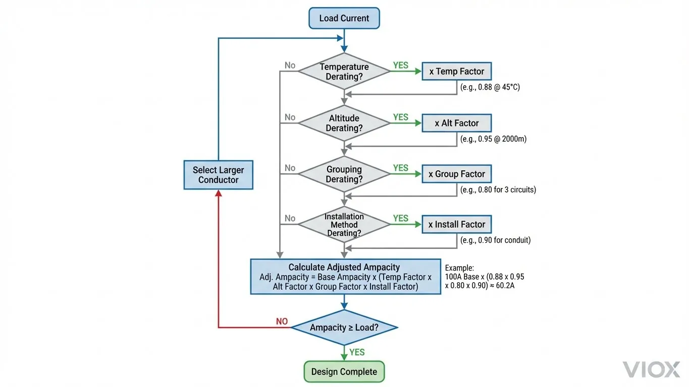
Section 4: Calculating Combined Derating Factors
The Multiplication Methodology
When multiple derating conditions exist simultaneously, factors are multiplied together to determine the final adjusted ampacity:
Master Formula:
Adjusted Ampacity = Base Ampacity × Temp Factor × Altitude Factor × Grouping Factor × Installation Factor
Step-by-step calculation process:
- Identify base ampacity from NEC Table 310.16 or IEC conductor tables (use 75°C or 90°C column based on terminal ratings per NEC 110.14(C))
- Determine all applicable derating factors for your specific installation
- Multiply factors together to get the cumulative reduction
- Calculate adjusted ampacity and compare to load requirements
- If adjusted ampacity < required ampacity, upsize the conductor and recalculate
Real-World Example: Solar Array DC Combiner
Scenario: 8 solar strings feeding a rooftop combiner box in Arizona summer conditions
Given parameters:
- Load current: 64A (8 strings × 8A each)
- Base conductor: 4 AWG copper THHN (85A @ 75°C, 95A @ 90°C)
- Ambient temperature: 50°C (rooftop exposure)
- Altitude: 1,100 meters
- Number of current-carrying conductors: 16 (8 positive + 8 negative)
- Installation: Cable tray, single layer
Calculation:
Base ampacity (90°C): 95A
Temperature factor (50°C): 0.82
Altitude factor (1,100m): 0.99
Grouping factor (16 conductors): 0.50

Adjusted ampacity = 95A × 0.82 × 0.99 × 0.50 = 38.7A
Result: 4 AWG is inadequate (38.7A < 64A required). Try 1/0 AWG (150A base):
Adjusted ampacity = 150A × 0.82 × 0.99 × 0.50 = 60.8A
Still inadequate. Final solution: 2/0 AWG (175A base):
Adjusted ampacity = 175A × 0.82 × 0.99 × 0.50 = 70.9A ✓
This example demonstrates why undersized conductors are common in solar installations—derating factors can reduce ampacity by 60% or more in harsh conditions.
Commercial EV Charging Station Example
Scenario: Underground feeder to 22kW Level 2 EV charger bank
Given parameters:
- Load current: 96A (three 32A chargers)
- Conductor: 3 AWG copper XHHW-2 (115A @ 75°C, 130A @ 90°C)
- Soil temperature: 30°C
- Burial depth: 0.8m
- Number of circuits in trench: 1 (3 conductors + ground)
- Continuous load factor: 1.25 (NEC 625.41 requires 125% sizing for EV equipment)
Calculation:
Base ampacity (90°C): 130A
Soil temp factor (30°C): 0.92
Depth factor (0.8m): 0.96
Continuous load requirement: 96A × 1.25 = 120A

Adjusted ampacity = 130A × 0.92 × 0.96 = 114.8A
Result: 3 AWG is inadequate (114.8A < 120A). Solution: 2 AWG (150A base):
Adjusted ampacity = 150A × 0.92 × 0.96 = 132.5A ✓
Understanding proper circuit breaker sizing for EV chargers requires coordinating conductor ampacity with OCPD ratings after all derating factors are applied.
Derating Factor Quick Reference Tables
Combined Temperature and Grouping Derating
| Scenario | Temp Factor | Group Factor | Combined | Example: 100A Base → Final Ampacity |
|---|---|---|---|---|
| 3 cables, 30°C | 1.00 | 1.00 | 1.00 | 100A |
| 6 cables, 40°C | 0.91 | 0.80 | 0.73 | 73A |
| 9 cables, 50°C | 0.82 | 0.70 | 0.57 | 57A |
| 15 cables, 50°C + altitude 2000m | 0.82 | 0.50 | 0.39* | 39A |
*Includes 0.94 altitude factor (0.82 × 0.50 × 0.94 = 0.385)
Installation Method Base Ratings Comparison
| Installation Method | Relative Ampacity | Typical Applications |
|---|---|---|
| Single cable in free air | 1.00 (highest) | Overhead spans, test setups |
| Clipped direct to surface | 0.95 | Industrial walls, structural mounting |
| In conduit/trunking (1-3 cables) | 0.80 | Building wiring, protected runs |
| Cable tray, single layer | 0.75 | Utility rooms, data centers |
| Buried direct in ground | 0.70 | Underground distribution |
| In underground duct | 0.65 | Long-distance transmission |
Frequently Asked Questions
Q1: Do I need to apply derating factors if my cable operates below its rated capacity?
Yes, derating factors are mandatory regardless of load percentage. They adjust the maximum safe ampacity of the conductor based on environmental conditions. The only exception is cables operating at less than 35% of their grouped rating over short distances (<3m), which may be excluded from grouping counts per IEC 60364-5-52.
Q2: Can I use the 90°C ampacity column for THHN wire if it terminates on a 75°C-rated circuit breaker?
Not for the final sizing decision. NEC 110.14(C) requires using the lower terminal temperature rating (75°C) for circuits ≤100A unless equipment is specifically listed for 90°C. However, you should use the 90°C base ampacity when applying derating factors, then verify the derated result doesn’t exceed the 75°C rating. This approach maximizes conductor capacity while ensuring safe terminations.
Q3: How do I handle mixed derating conditions, such as cables that are partially buried and partially in air?
Apply the most restrictive derating factor for the installation segment that constitutes the thermal bottleneck. For example, if 80% of a cable run is in free air but 20% passes through thermal insulation, the entire circuit must be derated for the insulated section. Conservative engineering practice is to always use worst-case conditions for the entire circuit length.
Q4: Are there exceptions for short cable runs that don’t require full derating?
Yes. NEC allows exemptions for nipples (short conduit sections ≤600mm) containing any number of conductors. IEC 60364-5-52 permits ignoring grouping derating for cable lengths under 1m for conductors <150mm² or 3m for conductors ≥150mm². However, temperature and altitude derating always apply regardless of cable length.
Q5: What derating factors apply to mineral-insulated (MI) cables?
MI cables (MIMS construction) have superior thermal performance and often require no derating for grouping when not in contact with other cable types. However, temperature and altitude derating still apply. Consult manufacturer specifications and AS/NZS 3008.1 or IEC 60702 for specific guidance on mineral-insulated conductors.
Q6: How do harmonics affect derating requirements?
Third harmonic currents in neutral conductors create additional I²R losses, requiring the neutral to be counted as a current-carrying conductor for grouping derating purposes. In installations with significant non-linear loads (VFDs, LED drivers, electronic ballasts), harmonic current content may necessitate neutral conductors sized at 200% of phase conductors and corresponding derating adjustments.
Q7: Can I compensate for high ambient temperature by oversizing the conductor instead of applying derating factors?
No. You must always apply the appropriate derating factors to determine the conductor’s adjusted ampacity, then select a conductor size where the adjusted ampacity meets or exceeds the load requirement. Simply oversizing without proper calculation violates NEC methodology and may still result in undersized conductors. The derating factors account for physics-based thermal limitations that cannot be ignored.
Conclusion: Engineering Excellence Through Proper Derating
Accurate derating calculations are non-negotiable for electrical safety, code compliance, and system longevity. The examples throughout this guide demonstrate that real-world installations commonly face 40-60% ampacity reductions compared to standard table values—a reality that demands rigorous engineering analysis.
Best practices for professional installations:
- Always use the highest conductor temperature rating (90°C) as the starting point for derating calculations
- Verify terminal temperature ratings and adjust final selections per NEC 110.14(C)
- Document all derating factors applied in your calculations for inspection compliance
- Consider future loading and apply 125% continuous load factors where applicable
- Specify quality circuit protection from manufacturers like VIOX that provide altitude-compensated ratings and thermal magnetic precision
VIOX Electric’s comprehensive line of industrial circuit breakers and protection devices are engineered with thermal management systems that maintain performance across temperature ranges of -40°C to +70°C and altitudes up to 4,000 meters. Our technical support team provides application-specific derating guidance for solar, EV charging, and industrial installations worldwide.
When specification accuracy matters, proper derating isn’t a calculation—it’s a commitment to safety. For technical consultation on your next project, contact VIOX Electric’s engineering team or explore our complete circuit protection solutions.
Related Technical Resources:
