Direct Answer: What Is a Modular Contactor?
A modular contactor is a DIN-rail mounted electromagnetic switching device used to control lighting, heating, ventilation, pumps, small motors, EV charger auxiliary circuits, and building automation loads. It works like a conventional contactor: when the coil is energized, the main contacts close or open to switch the load. The difference is that a modular contactor uses a compact modular format designed for distribution boards, consumer units, and DIN-rail control panels.
In many catalog and IEC 61095 contexts, this type of product may also be described as a household contactor or a contactor for household and similar applications. In product search and sourcing, however, modular contactor and DIN rail modular contactor are usually the more precise product terms.
The most important selection points are rated current, number of poles, coil voltage, contact configuration, utilization category such as AC-7a or AC-7b, wiring layout, noise level, and compatibility with auxiliary modules or smart control devices.
If you are selecting a modular contactor for a real project, do not choose only by the ampere rating printed on the front. The load type matters just as much as the current.


Modular Contactor at a Glance
| Item | Modular Contactor | Standard AC Contactor |
|---|---|---|
| Mounting | DIN rail modular format | DIN rail or panel mounting |
| Common location | Distribution board, consumer unit, small automation panel | Industrial control cabinet, motor starter panel, machine panel |
| Typical loads | Lighting, heating, small motors, fans, pumps, building automation | Motors, industrial machines, pumps, compressors, production equipment |
| Noise profile | Often designed for quieter switching in building environments | Switching sound is usually less important in industrial panels |
| Load category focus | AC-7a and AC-7b are often important | AC-1, AC-3, AC-4 and other IEC 60947 categories are often important |
| Standards context | IEC 61095 is commonly associated with household and similar modular contactors | IEC 60947-4-1 is commonly associated with industrial contactors and motor starters |
| Best fit | Compact switching inside modular boards | Heavier-duty industrial motor and machine control |
For product evaluation, see VIOX Modular Contactor and Modular Contactor Manufacturer pages.
How Does a Modular Contactor Work?
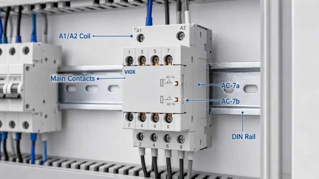
A modular contactor has three basic internal parts:
- Coil: creates a magnetic field when energized.
- Armature and mechanism: moves when the coil is energized.
- Main contacts: open or close the load circuit.
When control voltage is applied to the coil terminals, usually marked A1 and A2, the coil pulls the armature. This changes the state of the contacts and switches the load circuit. When the coil is de-energized, a spring returns the mechanism to its normal position.
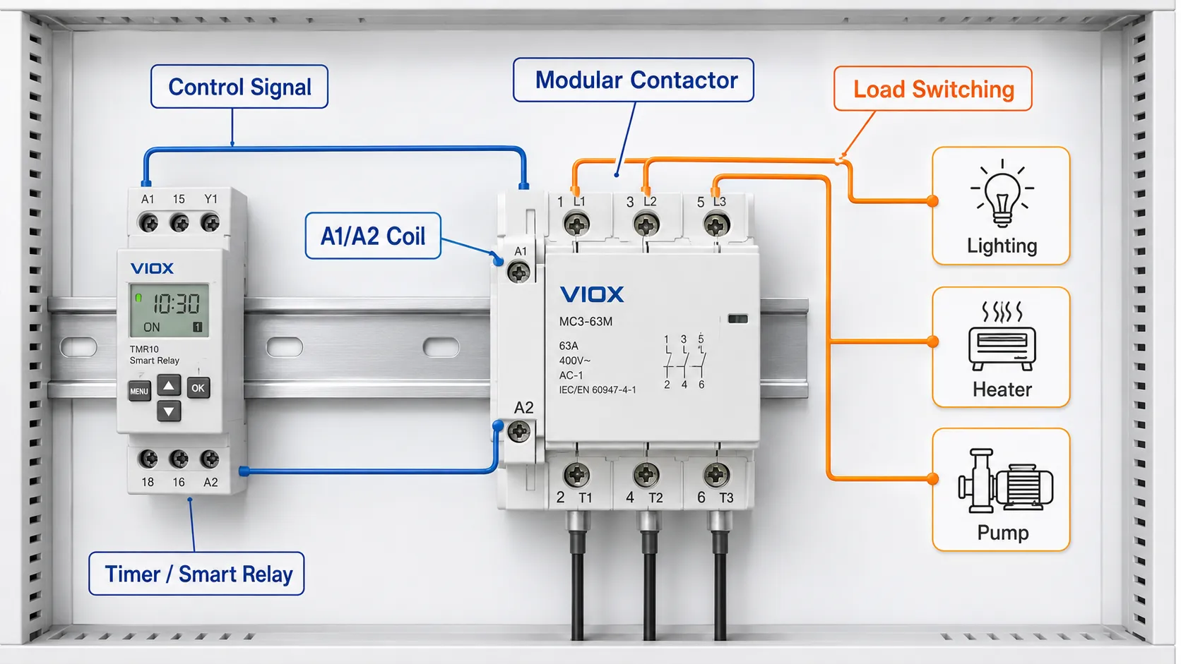
That makes the modular contactor useful when a small control signal needs to switch a larger load. For example, a timer relay, smart relay, thermostat, float switch, or building controller can energize the contactor coil while the contactor switches the lighting, heater, fan, or pump circuit.
For a deeper explanation of coil voltage behavior, see Relay Coil Voltage Explained.
Modular Contactor Wiring Diagram Basics
Always follow the wiring diagram printed on the contactor body and the manufacturer’s datasheet. Terminal markings vary by model, pole count, and contact arrangement.
A typical modular contactor wiring layout includes:
| Terminal Area | Typical Marking | Function |
|---|---|---|
| Coil terminals | A1 / A2 | Control voltage supply for the contactor coil |
| Main input terminals | 1, 3, 5 or L1, L2, L3 | Incoming supply side, depending on pole count |
| Main output terminals | 2, 4, 6 or T1, T2, T3 | Load side output |
| Auxiliary contacts | 13/14, 21/22 etc. | Status signal, interlock, or control feedback, if available |
Single-Phase Modular Contactor Wiring
For a simple single-phase load, a 2-pole modular contactor may switch line and neutral, or the required conductors according to the local wiring practice and project design.
Basic control idea:
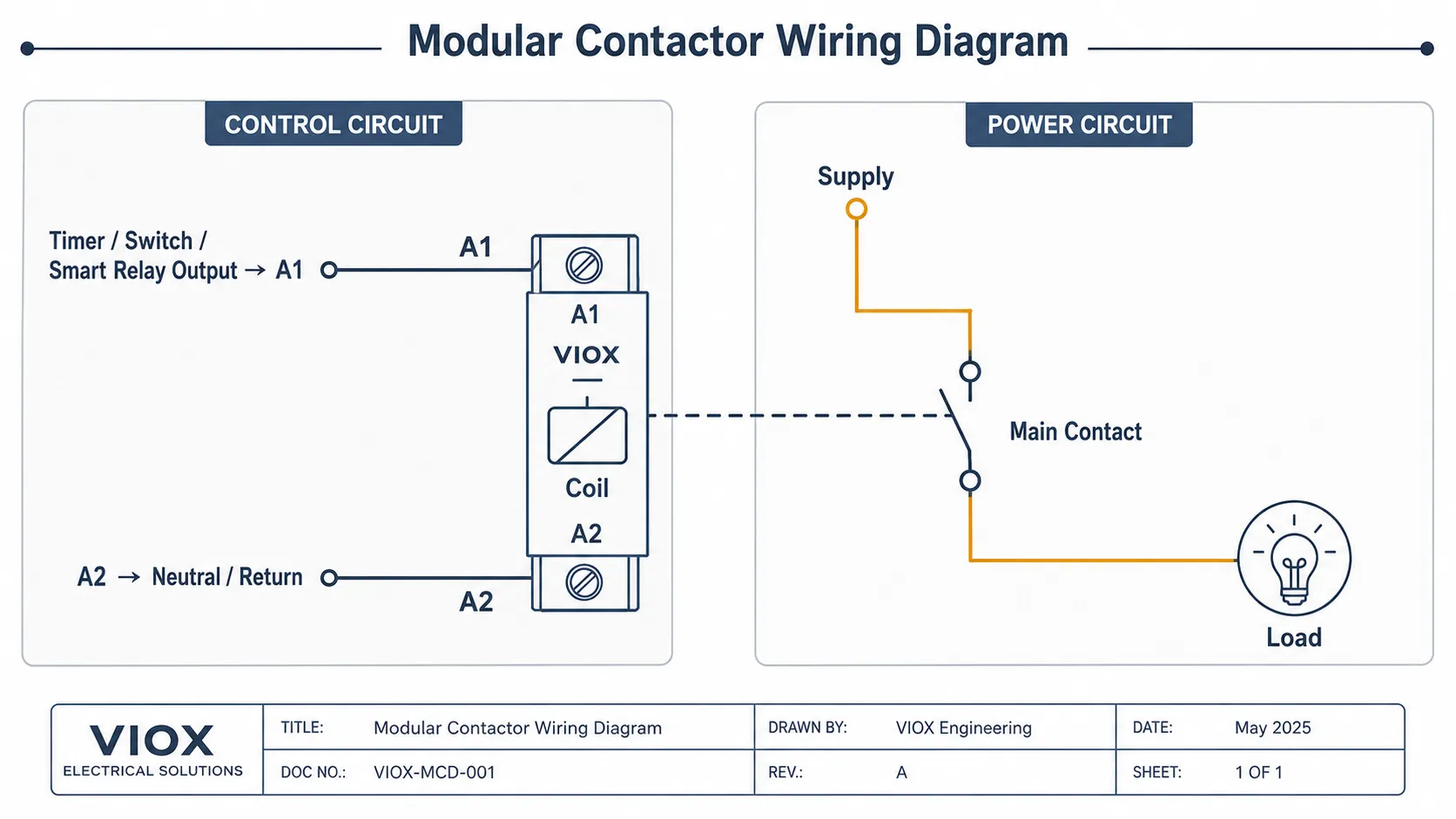
Control circuit:
Timer / switch / smart relay output -> A1 coil terminal
A2 coil terminal -> control neutral or return

Power circuit:
Supply line -> contactor main pole -> load line
Supply neutral -> second pole or neutral path as required by design
The control circuit and the power circuit should be understood separately. The A1/A2 coil terminals do not normally supply the load directly. They energize the coil, and the main contacts switch the load.
Three-Phase Modular Contactor Wiring
For three-phase loads, a 3-pole or 4-pole modular contactor may be used depending on whether neutral switching is required.
Basic concept:
L1 / L2 / L3 supply -> contactor input poles
Contactor output poles -> three-phase load
A1 / A2 coil -> control circuit
If the load is a motor, pump, fan, compressor, or other inductive load, confirm that the contactor is rated for that load category and starting behavior. Do not treat a modular contactor as a full industrial motor starter unless the design includes the required overload and short-circuit protection.
In a three-phase circuit, the modular contactor is only the switching element. The design still needs suitable upstream short-circuit protection, correct conductor sizing, correct terminal tightening according to the datasheet, and motor overload protection where required. A contactor that is correctly wired can still fail early if the utilization category, inrush current, or heat inside the enclosure is ignored.
For motor protection coordination, see How to Select Contactors, Overload Relays, and Circuit Breakers for Motor Power.
A1 and A2 Coil Terminals Explained
On many contactors and relays, A1 and A2 identify the coil or control supply terminals. The coil voltage may be 12V, 24V, 110V, 120V, 220V, 230V, or another value depending on the model.
Before wiring, check:
- AC or DC coil
- rated coil voltage
- frequency if AC
- polarity if DC
- allowable voltage range
- control device contact rating
- surge suppression requirement
- wiring diagram on the product
A common installation mistake is using a 230VAC control circuit on a 24V coil, or using a DC control supply on an AC-only coil. Either mistake can cause failure or non-operation.
If the control circuit uses a timer relay, the timer output contact must be rated for the modular contactor coil load. For timing applications, see What Is a Time Relay? and How to Choose the Right Timer Relay.
AC-7a vs AC-7b: The Rating That Many Buyers Miss
For modular contactors used in household and similar applications, AC-7a and AC-7b are important utilization categories.
| Utilization Category | Typical Load Type | What It Means for Selection |
|---|---|---|
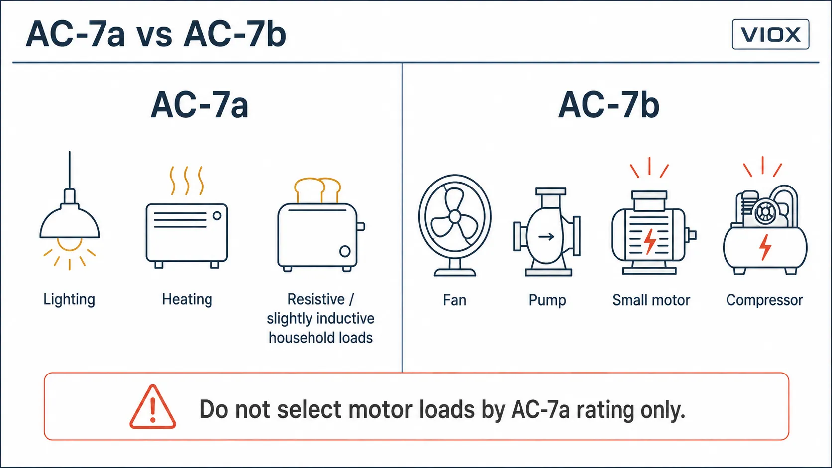
| AC-7a | Slightly inductive or resistive household/similar loads | Common for heating, lighting, and similar low-inrush loads |
| AC-7b | Motor loads for household/similar applications | Relevant for fans, pumps, compressors, and small motors with starting current |
The key point is simple:
If the modular contactor will switch a motor or inductive load, do not select only by the printed ampere rating. Check the AC-7b rating or the manufacturer’s load table.
For example, a contactor may have a higher current rating for resistive or slightly inductive loads than for motor loads. That does not mean the product is poor. It means the contact duty is different. Motor starting current, power factor, contact arcing, and switching frequency all affect electrical life.
IEC 61095 vs IEC 60947-4-1
Standards help clarify the intended application context.
| Standard Context | Typical Relevance | Practical Meaning |
|---|---|---|
| IEC 61095 | Electromechanical contactors for household and similar purposes | Commonly relevant to modular contactors used in distribution boards and similar installations |
| IEC 60947-4-1 | Contactors and motor-starters for industrial low-voltage switchgear and controlgear | Commonly relevant to industrial AC contactors and motor control applications |
Do not assume every modular contactor is an industrial motor contactor. Also do not assume every industrial contactor is suitable for quiet distribution-board switching. The correct device depends on the standard context, utilization category, load type, duty cycle, and project requirement.
If your application is an industrial motor starter, a standard AC Contactor or a complete motor starter design may be more appropriate than a modular contactor.
Is a Modular Contactor the Same as a Household Contactor?
The terms are closely related, but they are not always used in exactly the same way.
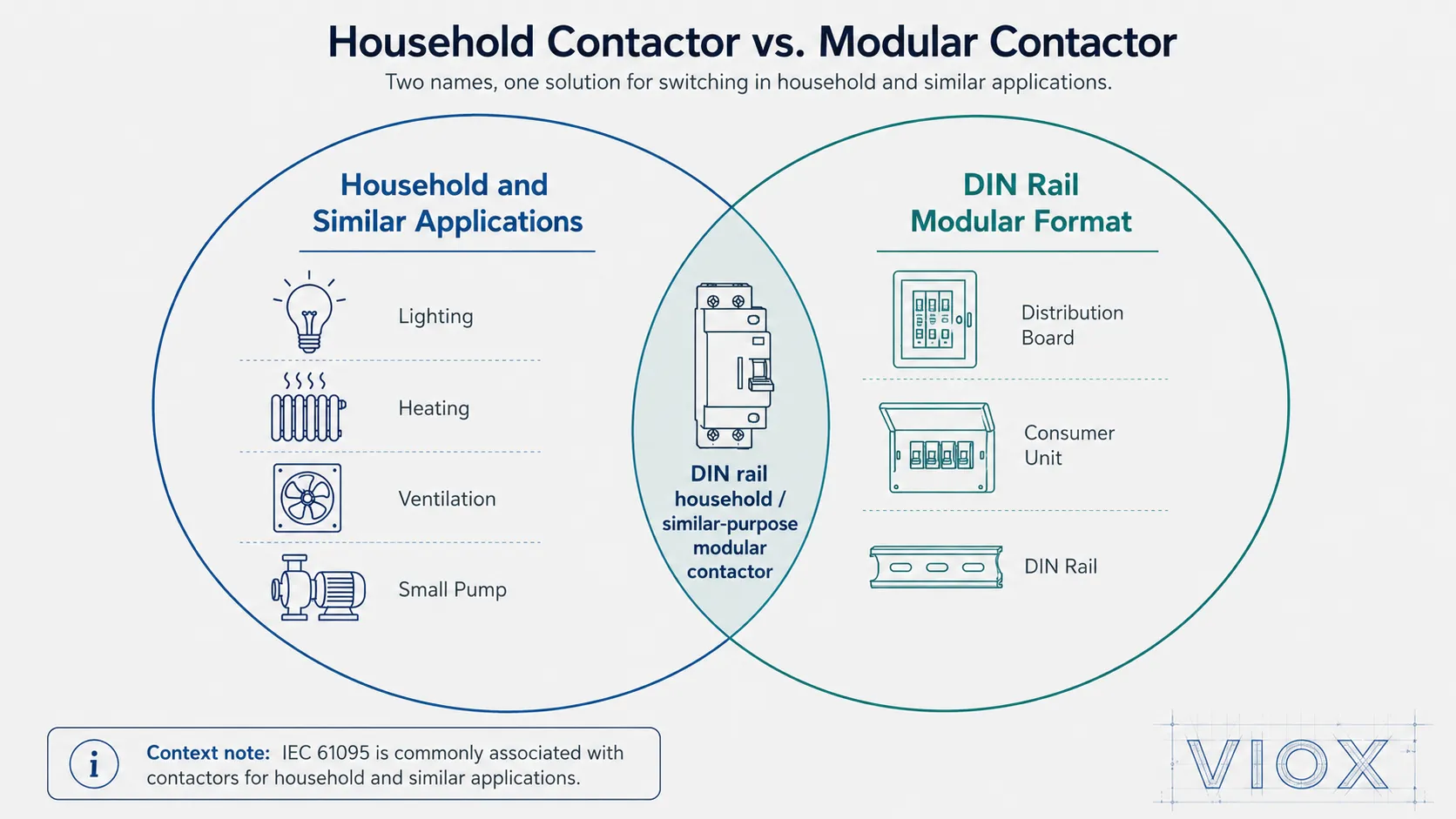
Household contactor usually refers to the application context: switching loads in household and similar installations, such as lighting, heating, ventilation, small pumps, or building-service circuits. This wording is strongly connected with IEC 61095-style usage.
Modular contactor usually refers to the product format: a compact DIN-rail contactor designed to fit modular distribution boards, consumer units, and small control panels.
In practice, many products are both: they are modular contactors used as household or similar-purpose contactors. The word “household” does not mean the device is used only in homes. It can also include similar residential, commercial, and light building-service applications, depending on the product rating, standard, and local project requirement.
A modular contactor is a DIN-rail household and similar-purpose contactor used for compact load switching in distribution boards and building automation circuits.
Where Are Modular Contactors Used?
Modular contactors are common in applications where loads need to be switched automatically from a compact DIN-rail board.
Typical applications include:
- lighting circuits in commercial buildings
- water heaters and heating loads
- ventilation fans
- small pumps
- small motors in building services
- HVAC auxiliary circuits
- smart home load control
- building automation panels
- timer-controlled circuits
- EV charger auxiliary control circuits
- load shedding or scheduled switching
The exact suitability depends on load current, inrush current, utilization category, coil voltage, switching frequency, and the protective devices used with the contactor.
Modular Contactors in Smart Control and Energy Management
A modular contactor is often used as the switching element behind a control signal.
Common control sources include:
| Control Source | Typical Use |
|---|---|
| Timer relay | Scheduled lighting, heating, ventilation, pump operation |
| Smart relay or automation module | Remote or programmed load control |
| Thermostat | Heating or ventilation control |
| Float switch | Pump control |
| Energy management controller | Load shedding or priority load switching |
| EV charger controller | Auxiliary switching or load management circuit |
The smart device usually should not directly switch the high-power load unless it is rated for that duty. Instead, it can switch the modular contactor coil, while the modular contactor switches the load.
This architecture keeps the control side simple and allows the contactor to handle the load current within its rated duty.
How to Choose a Modular Contactor
Use this checklist before choosing a model.
| Selection Item | What to Check | Why It Matters |
|---|---|---|
| Rated current | Load current under actual operating conditions | Prevents overheating and contact overload |
| Utilization category | AC-7a, AC-7b, or other applicable category | Matches the contactor to resistive, inductive, or motor loads |
| Pole number | 1P, 2P, 3P, 4P | Matches circuit wiring and isolation requirement |
| Coil voltage | AC/DC, 12V/24V/110V/230V etc. | Must match the control circuit |
| Contact configuration | Normally open, normally closed, mixed contacts | Determines switching logic |
| Load type | Lighting, heating, motor, pump, fan, EV auxiliary circuit | Affects inrush and contact wear |
| Switching frequency | How often the load is switched | Affects electrical life |
| Noise requirement | Quiet building board or industrial panel | Important in residential and commercial environments |
| Accessories | Auxiliary contacts, indicators, manual override, spacers | Helps with monitoring, interlock, and installation |
| Standards and documentation | IEC 61095, IEC 60947 context, local project requirement | Needed for approval and specification compliance |
Field Example: When a Lighting Contactor Becomes a Motor Problem
In panel reviews, a common mistake is using a modular contactor that was originally selected for lighting or heating duty to switch a small fan or pump. The running current may look acceptable, but the starting current and inductive load behavior can be much harder on the contacts than a resistive load.
This is why AC-7a and AC-7b should be checked before approving the part. A motor load may draw several times its running current during starting, depending on motor type, supply conditions, and mechanical load. The exact value should come from the motor data, equipment manufacturer, or project calculation, not from a generic rule of thumb.
Expert Tip: In real panel reviews, the running current of a small pump or fan is often much lower than its starting current. Some small motors can draw several times their rated running current during startup, depending on motor design, supply voltage, load inertia, and starting method. This is why AC-7b or the manufacturer’s motor-load table matters. AC-7a is suitable for resistive or slightly inductive household loads, but it should not be used as the only basis for motor-duty selection.
For a fan, pump, compressor, or small motor, confirm:
- AC-7b or manufacturer motor-load rating
- switching frequency
- coil voltage stability during start
- upstream short-circuit protection
- overload protection if the motor requires it
- terminal conductor size range from the datasheet
- manufacturer terminal torque requirement
- enclosure temperature and ventilation
This kind of check is more useful than simply asking whether the contactor is “large enough” in amperes.
Pole Number: 1P, 2P, 3P, and 4P
Pole count determines how many conductors the contactor switches.
| Pole Count | Typical Use |
|---|---|
| 1P | Single conductor switching in simple control circuits |
| 2P | Single-phase loads where two conductors are switched |
| 3P | Three-phase loads without neutral switching |
| 4P | Three-phase plus neutral switching or multi-conductor control needs |
Do not select pole count only by convenience. Follow the circuit design, local wiring rules, neutral switching requirement, and isolation strategy.
Mounting Options and Modular Accessories
One reason modular contactors are popular is installation convenience. They are usually designed for DIN rail mounting and can be installed beside MCBs, RCBOs, timers, relays, meters, and other modular devices.
Useful accessory or design features may include:
- auxiliary contact module
- manual operation or test lever, depending on model
- indicator window
- spacer for heat dissipation
- sealable cover
- low-noise coil design
- compatible busbar or wiring accessories, where supported
- clear terminal marking
For panel builders, accessory compatibility can reduce wiring time and make maintenance easier. But accessory availability must be checked for the exact product series, not assumed from the word “modular.”
Modular Contactor vs Relay vs Timer Relay
These devices are related but not interchangeable.
| Device | Main Job | Typical Use |
|---|---|---|
| Modular contactor | Switches load circuits using electromagnetic contacts | Lighting, heating, fans, pumps, building automation loads |
| Control relay | Switches lower-power control signals | Interlocks, signaling, PLC inputs, control logic |
| Timer relay | Changes contact state after a time delay | Delayed start/stop, cyclic timing, lighting or pump timing |
| Standard AC contactor | Switches industrial loads and motors | Motor starters, machinery, industrial control panels |
A timer relay can control the coil of a modular contactor, but it normally should not replace the contactor when the load current exceeds the timer relay contact rating.
Common Selection Mistakes
Mistake 1: Selecting Only by Ampere Rating
The printed current rating is not enough. Check the utilization category and load type. A motor load can stress contacts differently from a resistive heating load.
Mistake 2: Ignoring AC-7a vs AC-7b
If the load is a fan, pump, compressor, or motor, AC-7b rating matters. Using only an AC-7a rating for a motor duty can lead to poor service life or contact problems.
Mistake 3: Using a Modular Contactor as a Complete Motor Starter
A contactor is a switching device. A motor circuit also needs overload protection and short-circuit protection. The modular contactor does not automatically provide those functions by itself.
Mistake 4: Choosing the Wrong Coil Voltage
The control circuit must match the coil voltage. Check AC/DC type, voltage value, and polarity before wiring.
Mistake 5: Letting a Smart Module Switch the Load Directly
A smart relay or controller may be suitable for control signaling but not for switching the load directly. Use it to energize the contactor coil when the load current or inrush exceeds the controller rating.
Mistake 6: Ignoring Heat in a Crowded DIN Rail Board
Multiple modular devices packed tightly in a distribution board can generate heat. Check spacing, ventilation, rated current, and manufacturer installation guidance.
FAQ
What is a modular contactor?
A modular contactor is a compact DIN-rail contactor used to switch electrical loads from a control signal. It is commonly installed in distribution boards, consumer units, and building automation panels.
What is the difference between a modular contactor and a normal contactor?
A modular contactor is designed in a compact modular DIN-rail format, often for building and distribution-board applications. A normal AC contactor is usually designed for industrial control panels, machine loads, and heavier motor-control duties.
How do you wire a modular contactor?
The coil terminals, often A1 and A2, connect to the control circuit. The main contacts switch the load circuit. Always follow the printed wiring diagram and datasheet for the exact model.
What are A1 and A2 on a modular contactor?
A1 and A2 are commonly the coil terminals. Applying the correct control voltage to A1/A2 energizes the contactor coil and changes the state of the main contacts.
What is AC-7a on a modular contactor?
AC-7a is a utilization category commonly associated with slightly inductive or resistive household and similar loads, such as heating and certain lighting applications.
What is AC-7b on a modular contactor?
AC-7b is a utilization category for motor loads in household and similar applications. It is important when switching fans, pumps, compressors, or small motors.
Can a modular contactor control a motor?
Yes, if the contactor is rated for the motor load and the circuit includes suitable overload and short-circuit protection. Check AC-7b rating, starting current, switching frequency, and manufacturer guidance.
Can a timer relay control a modular contactor?
Yes. A timer relay can energize the modular contactor coil if its output contact is rated for the coil load. The modular contactor then switches the power load.
Is a modular contactor the same as a smart contactor?
Not necessarily. A modular contactor is a mechanical switching device in a modular form factor. It becomes part of a smart control system when driven by a timer, smart relay, automation controller, or energy management device.
Which standard applies to modular contactors?
IEC 61095 is commonly associated with electromechanical contactors for household and similar purposes. IEC 60947-4-1 is commonly associated with industrial contactors and motor starters. The applicable standard depends on the product and project requirement.
Conclusion
A modular contactor is best understood as a compact DIN-rail load-switching device for distribution boards and building automation circuits. It is useful for lighting, heating, ventilation, pumps, small motors, timer-controlled circuits, and smart energy management applications.
To select one correctly, check the load type first. Then confirm rated current, AC-7a or AC-7b duty, coil voltage, pole count, contact configuration, wiring diagram, accessories, and protection coordination. If the load is a motor or industrial machine, do not treat the modular contactor as a complete motor starter by itself.
VIOX supplies modular contactors and related control products for DIN rail distribution, building automation, timer-controlled loads, and OEM panel projects. Start with the Modular Contactor product page, or compare related options such as AC Contactors and Timer Relays.
