On this page
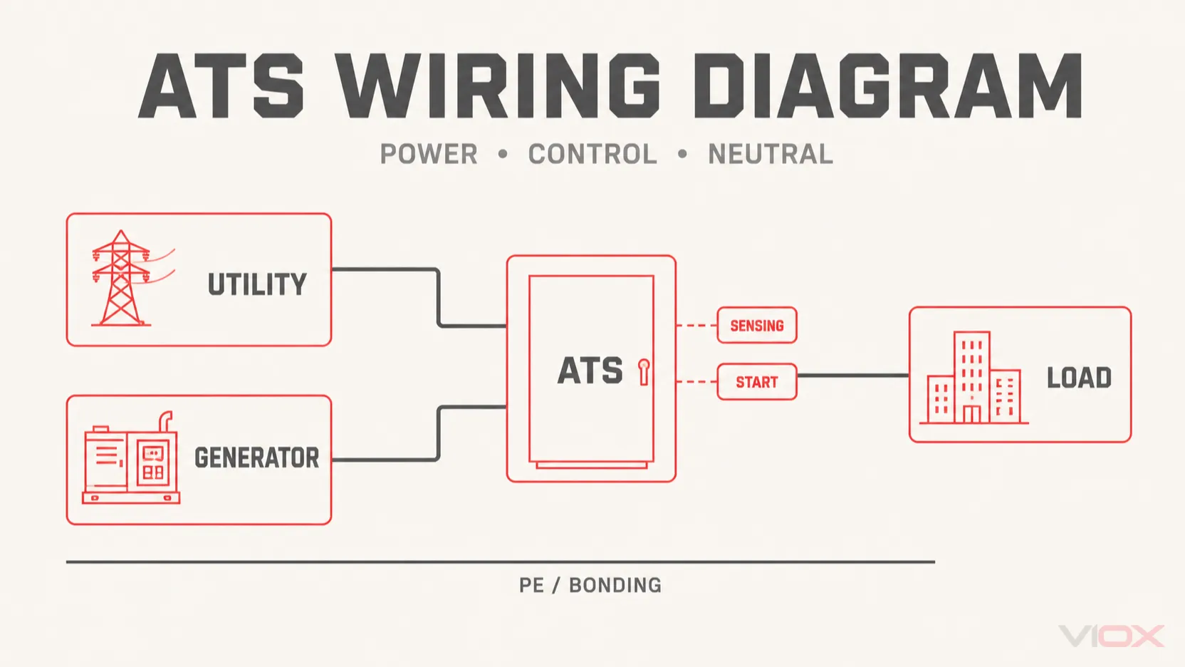
An automatic transfer switch (ATS) wiring diagram has two layers. The power layer routes the normal source and alternate source to one common load without paralleling them in a conventional open-transition arrangement. The control layer senses source conditions, operates the transfer mechanism, and may command a compatible generator controller to start or stop.
The generic relationship is:
Utility → source protective device → ATS normal input
Generator → generator protective device → ATS alternate input
ATS common output → downstream distribution/protection → load
Neutral may remain continuously connected or may pass through a dedicated transfer pole, depending on the grounding, bonding, ground-fault protection, and equipment design. The protective earth/equipment grounding conductor (PE) belongs to the protective bonding network; it is not a normal load-current path and should not be shown passing through an ordinary ATS transfer contact.
Conceptual reference only: The diagrams on this page explain functions and conductor relationships. They do not define terminal numbers, conductor sizes, torque, control voltage, protection ratings, grounding/bonding points, or a safe installation procedure. Use the exact ATS, generator, controller, and distribution-equipment drawings for design and installation.
ATS Wiring Diagram Legend
Use this legend for every diagram on this page.
| Graphic element | Meaning | What it does not prove |
|---|---|---|
| Heavy solid line | Main power conductor or bus | Conductor size, ampacity, insulation, or terminal location |
| Thin solid line | Sensing, control power, command, or status circuit | Control voltage, wet/dry contact type, polarity, or pin number |
| Dashed line | Functional or logical relationship | A physical cable or a universal communication protocol |
| Source OCPD | MCB, MCCB, fuse, generator breaker, or other specified overcurrent protective device | That every ATS includes this protection internally |
| Transfer pole | One switched current path between Source I, Source II, and the common load | Utilization category, transition type, withstand rating, or neutral suitability |
| Solid-neutral bar | Neutral remains connected outside the switched poles | That this arrangement is correct for every generator or ground-fault scheme |
| Switched-neutral pole | Neutral transfers with the phase conductors through a dedicated pole | The required bonding arrangement or pole timing for a particular system |
| PE/bonding line | Protective earth and equipment-bonding path | A normal neutral return path or permission to switch PE |
The IEC term transfer switching equipment (TSE) is broader than the common term ATS. IEC 60947-6-1:2026 covers low-voltage TSE within its stated scope and includes automatic, remote, manual, bypass/isolation, and other defined arrangements. In North America, UL Solutions identifies UL 1008 for automatic and nonautomatic transfer-switch equipment categories. Neither standard name replaces the exact product drawing or the installation rules for the project.
Utility–Generator–ATS–Load Single-Line Diagram
The first diagram should answer one question: which source can feed the common load, and where does protection sit?
The utility and generator are separate source paths. Each path normally reaches the ATS through the protective and disconnecting arrangement required for that source and installation. Inside the ATS, an interlocked switching mechanism selects Source I or Source II. The common output then supplies a downstream distribution board, feeder, or defined load.
| Block | Conceptual function | Verify on the project |
|---|---|---|
| Utility / normal source | Preferred supply under normal conditions | Voltage, phase, frequency, grounding method, service/feeder arrangement |
| Utility-side OCPD/disconnect | Protects and/or disconnects the normal-source circuit as designed | Device type, rating, location, service suitability, ATS withstand-and-closing conditions |
| Generator / alternate source | Supplies the load after it is available and acceptable | Rated output, phase sequence, neutral bond, generator breaker, automatic-start interface |
| Generator-side OCPD | Protects the generator feeder and provides the required source disconnect function | Generator breaker rating, conductor coordination, applicable installation rules |
| ATS Source I and Source II | Receives the two source power paths | Which input is preferred, terminal location, phase order, allowed top/bottom feed |
| ATS common load output | Connects the selected source to the load | Terminal identity, current rating, transition logic, switched conductors |
| Downstream distribution/OCPD | Distributes and protects load circuits | Whether protection is integrated, upstream, downstream, or split across the system |
| PE/bonding network | Bonds exposed conductive parts and provides the protective fault-current path | Enclosure bonding, grounding electrode connection, neutral-bond location, local rules |
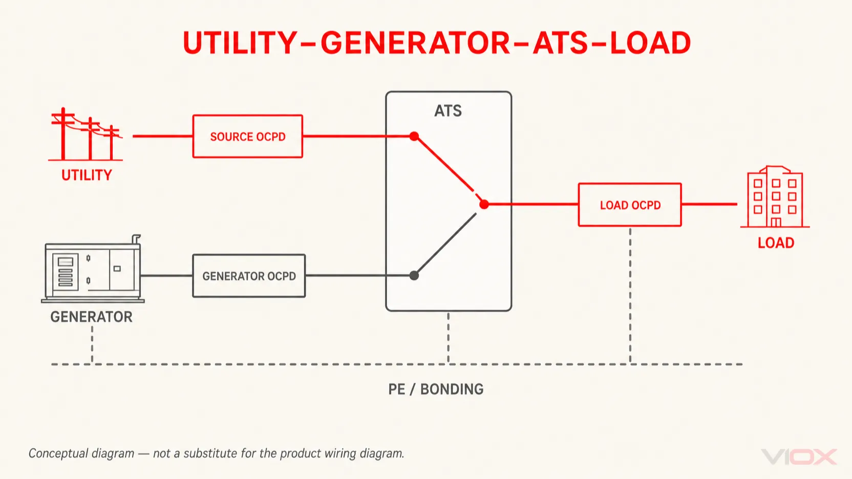
Do not infer that the ATS contains an MCB or molded-case circuit breaker (MCCB). Some transfer systems use contactors or switch-disconnectors with external protection; some CB-class arrangements use circuit breakers as the switching devices; and some service or distribution assemblies integrate functions that a standalone ATS does not. The PC Class vs CB Class ATS guide explains that equipment distinction, while the ATS and circuit-breaker coordination guide addresses fault-duty and protective-device coordination.
Conceptual diagram — not a substitute for the product wiring diagram. Source protection, load protection, service-disconnect functions, terminal orientation, neutral treatment, and PE/bonding must be verified for the exact equipment and installation.
Power Terminals, Sensing Terminals and Generator Start Contacts
A common wiring error in conceptual discussions is treating every small terminal as a generator-start connection. Real ATS controllers may have several distinct low-power functions:
| Terminal family | Typical function | Important boundary |
|---|---|---|
| Main power terminals | Normal source, alternate source, and common load conductors | Their labels and physical positions are product-specific |
| Source sensing | Measures voltage, frequency, phase loss, phase sequence, or other supported source conditions | Sensing may be internally derived from power terminals or externally wired through specified circuits |
| Controller power | Powers the ATS controller, motor, coils, or stored-energy mechanism | It may come from one or both sources or an auxiliary supply; never assume the voltage |
| Engine/generator start output | Requests start/stop from a compatible generator controller | Often a relay contact, but contact form, rating, logic, and whether it is dry or powered are model-specific |
| Position/status contacts | Reports Source I, Source II, open, alarm, or mechanism status | These are indication/logic contacts, not main power outputs |
| Remote input/communication | Test, inhibit, transfer, fire signal, load-shed, or communications functions | Availability and priority logic vary by controller and project |
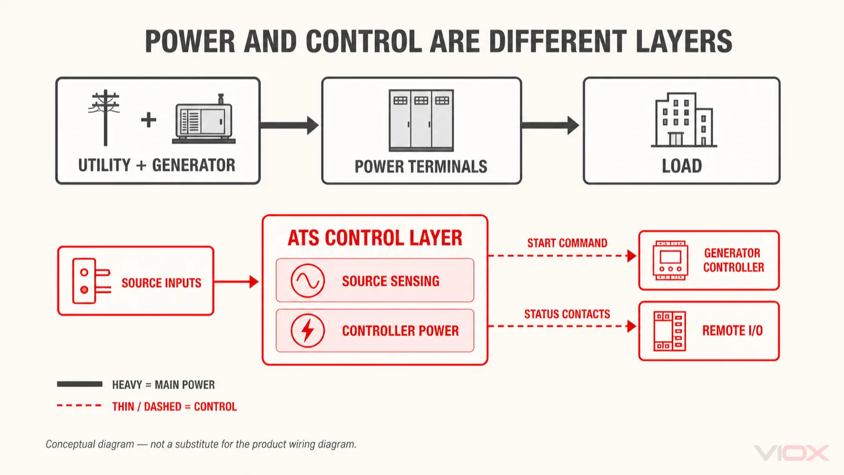
The control relationship for a generator-backed ATS is conceptual:
- The ATS controller evaluates the normal source through its sensing path.
- When its programmed logic declares the source unacceptable, the controller may operate a model-specific start output.
- The generator controller—not the ATS power contacts—cranks and regulates the engine-generator.
- The ATS evaluates the alternate source through its supported sensing arrangement.
- When the controller conditions and delays are satisfied, the transfer mechanism changes the load connection.
ABB’s current OTM_C_D technical documentation illustrates why these layers must be separated: its main-circuit diagram, controller-terminal connections, generator-start output, status detection, motor supply, and control supplies appear as distinct circuits. A Generac residential ATS drawing uses labels such as N1, N2, E1, E2, T1, and T2, but those labels belong to that product family; they are not a universal ATS pinout.
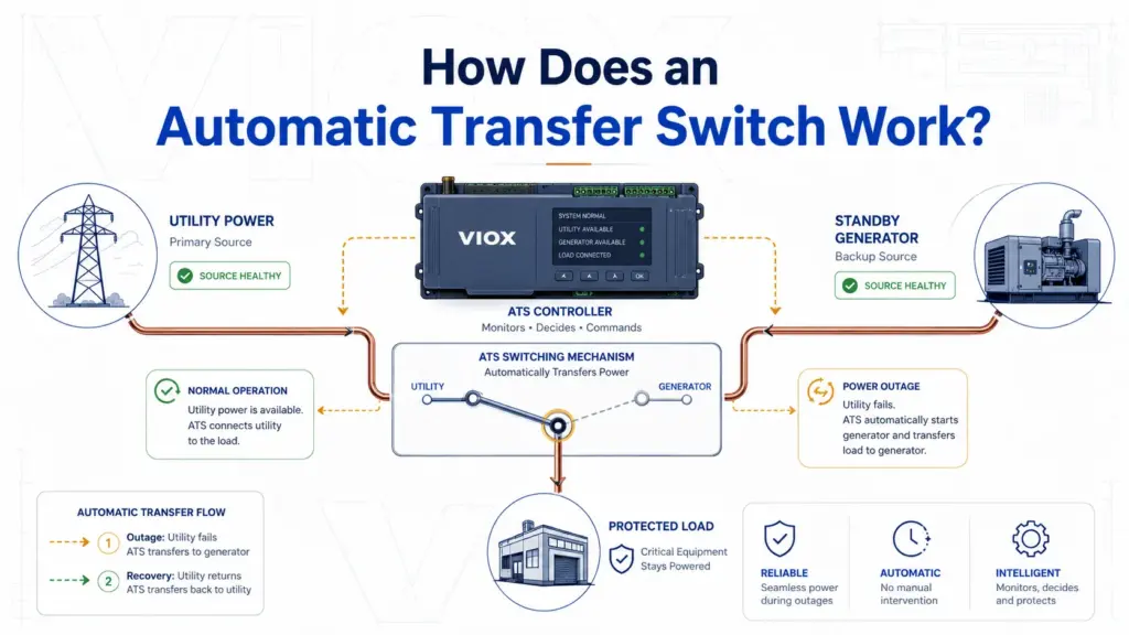
For the detection, start, source-acceptance, transfer, retransfer, and cooldown sequence, see How Does an Automatic Transfer Switch Work?.
Conceptual diagram — not a substitute for the product wiring diagram. Verify whether sensing is internal or external, the controller supply, generator-start contact form and rating, fail-safe state, auxiliary-contact ratings, communications, and terminal numbering.
Single-Phase 2P ATS Wiring Diagrams
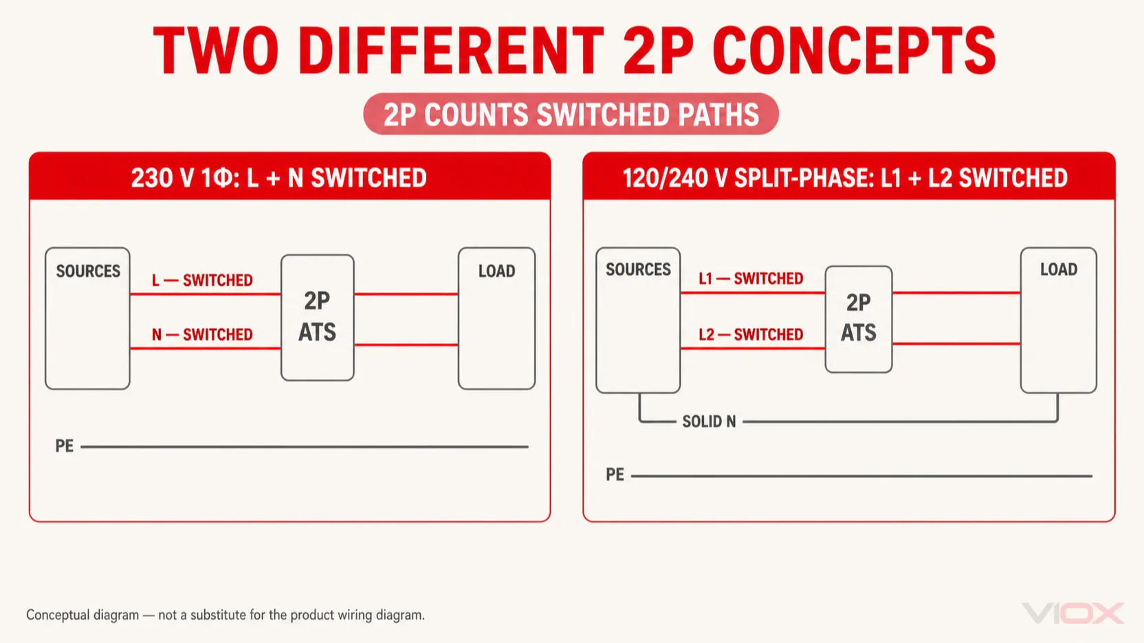
The label 2P means that two current paths are switched. It does not, by itself, identify the voltage system or prove whether one of those paths is neutral.
230 V single-phase, line and neutral transferred
In a common 230 V line-to-neutral system, a 2P ATS may use one pole for line L and the second pole for neutral N. Both sources therefore present L + N to the switch, and the common output presents L + N to the load.
This drawing is valid only as a conductor-path concept. The required neutral switching, neutral-pole construction and timing, source bonding, and protective-device behavior must come from the system design and product documentation.
120/240 V split-phase with solid neutral
In a North American 120/240 V split-phase system, a 2P ATS may switch the two ungrounded conductors L1 and L2 while the neutral remains solid. That is also a “single-phase 2P ATS,” but it is not the same conductor arrangement as a 230 V L + N two-pole transfer.
If the split-phase neutral must be transferred, the equipment needs a suitable additional neutral pole or another listed/configured arrangement. Do not draw L1, L2, and N through only two poles.
| System concept | Two switched paths | Neutral treatment | Do not assume |
|---|---|---|---|
230 V single-phase L + N |
L and N |
Switched neutral | That every 2P device has a suitably rated neutral pole |
120/240 V split-phase L1 + L2 + N |
L1 and L2 |
Solid neutral outside the two poles | That a solid neutral is correct for every generator/bonding scheme |
| Two-wire line-to-line load | Two ungrounded conductors | No load neutral | That the source and load require no neutral elsewhere |
The detailed choice belongs on the 2P vs 3P vs 4P ATS selection page; this reference shows only how to read the resulting conductor paths.
Conceptual diagram — not a substitute for the product wiring diagram. “2P” counts switched paths; it does not universally mean line-plus-neutral, split phase, a particular voltage, or a particular grounding method.
Three-Phase ATS Wiring Diagram: 3P vs 4P
A three-phase ATS diagram must state whether the load system has a neutral and whether that neutral is solid or switched.
3P ATS
A 3P transfer mechanism switches L1, L2, and L3. It directly represents a three-phase three-wire load when no neutral is required. In a three-phase four-wire system, a 3P ATS may be used with a solid neutral that connects outside the three transfer poles—but only when that neutral and grounding arrangement is correct for the sources, protection, and applicable rules.
4P ATS
A 4P transfer mechanism switches L1, L2, L3, and N. The fourth pole provides a transferred-neutral path. It does not, by itself, prove that the generator is a separately derived system, that every neutral bond is correct, or that the pole sequence suits the ground-fault protection scheme.
| Diagram | Switched conductors | Neutral shown | Typical conceptual use |
|---|---|---|---|
| 3P, three-wire | L1, L2, L3 |
None required by the depicted load | Three-phase load/distribution without a neutral conductor |
| 3P, four-wire with solid neutral | L1, L2, L3 |
Continuous neutral outside switching poles | Four-wire system whose verified design retains a common neutral |
| 4P, four-wire with switched neutral | L1, L2, L3, N |
Neutral passes through dedicated transfer pole | Four-wire system whose verified design transfers neutral with the source |
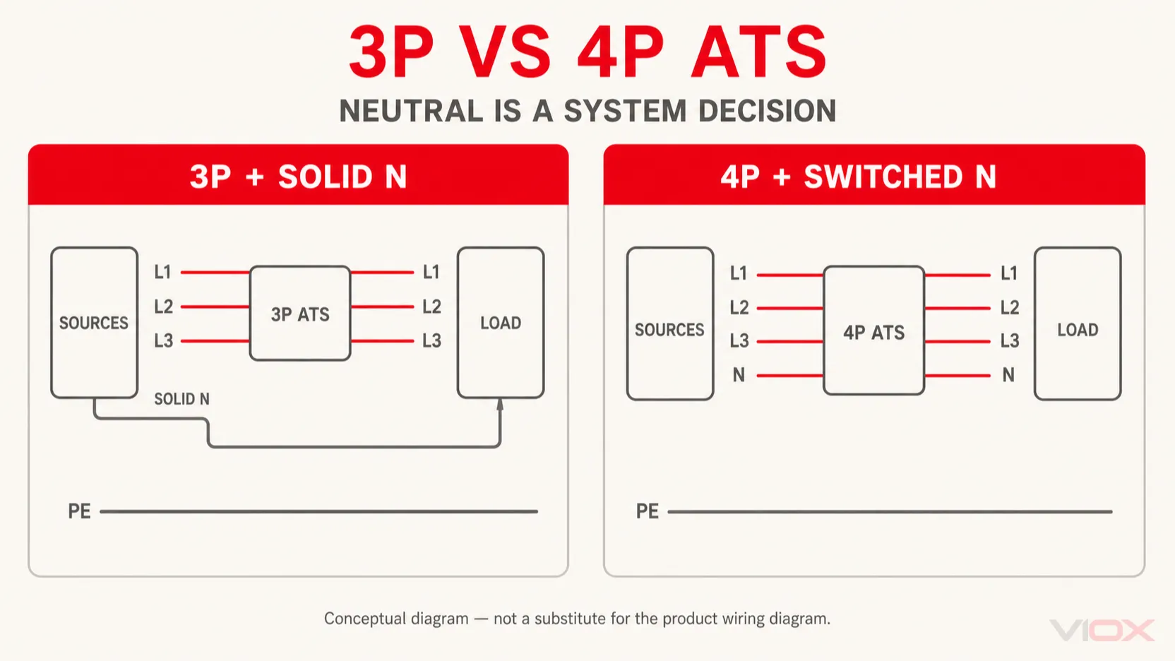
ASCO’s neutral configuration bulletin states that transfer switches are available with or without a dedicated neutral pole and relates the decision to whether the alternate supply uses a separately derived grounding arrangement. That is the correct level of generalization: switched neutral is a system decision, not a universal synonym for “safer.”
For hybrid inverters, batteries, source-dependent bonding relays, and two-wire generator start, use the separate Hybrid Inverter ATS Wiring Guide and then verify the actual inverter, ATS, and generator manuals.
Conceptual diagram — not a substitute for the product wiring diagram. Verify system conductors, phase sequence, neutral-pole rating and timing, source bonding, ground-fault protection, and controller sensing for the exact project.
Solid Neutral, Switched Neutral and PE Boundaries
Neutral and PE must not be drawn as interchangeable conductors.
Solid neutral
A solid-neutral arrangement keeps the source and load neutrals connected through a continuous neutral path outside the switched phase poles. This can be valid where the grounding and bonding design intentionally uses a common neutral reference. It can be incorrect where the alternate source, ground-fault scheme, or local rules require neutral isolation.
Switched neutral
A switched-neutral arrangement routes neutral through a dedicated transfer pole. The equipment documentation must establish the neutral pole’s rating and switching sequence. Some applications require overlapping or delayed neutral behavior rather than treating the neutral pole as identical to a phase pole, so “4P” alone is not a complete specification.
Protective earth/equipment grounding conductor
PE bonds exposed conductive parts and forms part of the protective fault-current path. In the conceptual drawings, it should connect the generator frame/enclosure, ATS enclosure, downstream equipment, and grounding/bonding network as the design requires. It should not be routed through a normal ATS source-selection contact or drawn as though it transfers between Source I and Source II.
This does not determine where neutral-to-ground bonds or grounding electrode connections belong. Those locations depend on service-equipment status, source bonding, separately derived system treatment, equipment construction, and the applicable installation framework. Manufacturer interconnection drawings commonly show ground bars and grounding/bonding connections separately from the phase and neutral power terminals for this reason.
Where MCBs and MCCBs Appear Around an ATS
A transfer switch selects a source. Unless the product explicitly integrates suitable overcurrent protective devices, it should not be assumed to protect source or load conductors against overload or short circuit.
The conceptual protection map is:
- Normal source: service/feeder protective and disconnecting arrangement before the ATS as required by the design.
- Generator source: generator breaker or specified feeder protection before the alternate ATS input.
- ATS: selected for load current, switching duty, poles, transition, controller functions, and the available fault conditions with the specified protective devices.
- Load side: feeder or branch protection at the downstream distribution equipment, unless a verified integrated assembly provides the required function.
An MCB may be appropriate in a small low-voltage system; an MCCB, fuse, power circuit breaker, or other device may be required in a larger or higher-fault-duty installation. The diagram cannot select among them without load current, conductor, system voltage, fault-current, coordination, service, and product data.
How to Translate This Reference to a Product Wiring Diagram
Before anyone designs or installs the circuit, replace every generic block with verified product information.
| Generic reference label | Find this in the exact documentation |
|---|---|
| Source I / normal / utility | Terminal names and locations, preferred-source logic, allowed feed direction, voltage and phase |
| Source II / alternate / emergency | Terminal names and locations, generator/source requirements, phase sequence |
| Common load | Load terminal identity, conductor capacity, downstream arrangement |
| Sensing | Internal or external sensing points, fuses, range, phase/frequency functions |
| Controller power | Supply source, voltage, polarity, protective device, loss-of-power behavior |
| Generator start | Contact form, normal state, rating, powered or dry interface, start/stop logic, generator compatibility |
| Neutral | Solid or switched, pole rating/timing, bonding and ground-fault implications |
| PE/ground | Enclosure bonding, equipment grounding, grounding electrode and service/source bonding instructions |
| Source/load OCPD | Device type, current rating, interrupting capacity, ATS WCR/SCCR or IEC coordination conditions |
| Auxiliary I/O | Status, alarm, test, inhibit, fire input, load shed, communications, priority logic |
Reject the generic diagram as an installation basis if the exact ATS drawing, generator interface documentation, source and load one-line, neutral/bonding plan, or protective-device coordination is missing.
For the broader equipment concept and terminology, start with What Is a Dual Power Automatic Transfer Switch?. After the architecture is defined, the Generator Transfer Switch Guide provides the specification workflow. Qualified buyers and panel builders can then compare the VIOX ATS range against the required voltage, current, poles, transfer logic, fault-duty and documented control interface; confirm every value from the selected model data before procurement.
Sources
- IEC 60947-6-1:2026 — Transfer Switching Equipment
- UL Solutions — Switch Certification and Evaluation Services
- ABB — OTM_C_D Automatic Transfer Switch Catalog and Technical Diagrams
- Generac — Automatic Transfer Switch Owner’s Manual and Wiring Drawings
- Schneider Electric / ASCO — Neutral Configurations in Transfer Switches
- Schneider Electric / ASCO — Series 200 Single-Phase Wiring Diagram
- Eaton — ATC-100 Contactor-Based Transfer Switch Instructions