On this page
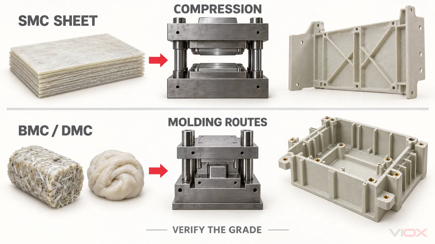
For circuit-breaker insulation parts, sheet molding compound (SMC) is normally the stronger starting direction for larger compression-molded structural parts, while bulk molding compound (BMC) and dough molding compound (DMC) are normally better starting directions for smaller, thicker, more intricate, or insert-rich parts. This is not a universal material ranking. The exact compound grade, fibre architecture, molding route, part geometry, and finished-device verification determine whether a material is suitable.
The most important rule is that a material name does not establish a circuit breaker’s rating. A value such as PTI 600, GWFI 960 °C, a dielectric-strength result, or a V-0 classification describes performance under a defined material test. It does not independently prove the breaking capacity, insulation coordination, temperature rise, mechanical endurance, or conformity of a finished breaker.
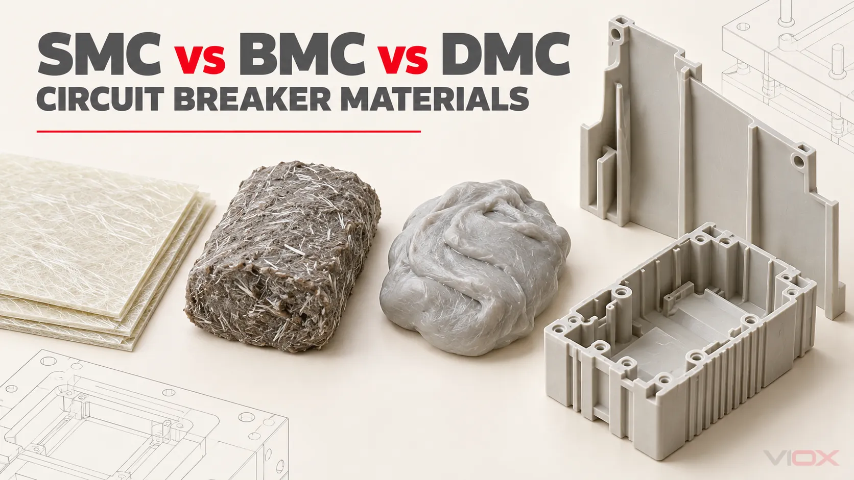
SMC, BMC, and DMC at a Glance
| Decision dimension | SMC | BMC | DMC |
|---|---|---|---|
| Full term | Sheet Molding Compound | Bulk Molding Compound | Dough Molding Compound |
| Supplied form | Prepared sheet, usually carried between films | Bulk, log, lump, or charge form | Dough-like bulk charge |
| Reinforcement direction | Commonly longer chopped fibres than conventional BMC/DMC grades | Commonly shorter chopped fibres | Closely related to BMC; the precise distinction depends on the specification and formulation |
| Normal processing direction | Compression molding | Compression, transfer, or injection molding when the grade permits | Compression or another molding route permitted by the grade and process |
| Typical design strength | Larger-area or structural insulation parts where stiffness and impact performance matter | Detailed three-dimensional parts, bosses, ribs, embedded metal, and complex cavities | Similar bulk-form applications; verify whether the supplier treats DMC as a synonym, regional term, or separate formulation |
| Main caution | Flow, fibre orientation, charge placement, and complex-detail filling must be engineered | Shorter fibres and flow can reduce structural or impact performance relative to a selected SMC grade | The abbreviation alone does not define thickening method, fibre, resin, or performance |
Use this table to choose a development direction, not to approve a material. The complete material specification and molded-part validation remain necessary.
What the Three Terms Actually Mean
SMC: a prepared sheet molding charge
SMC is made by combining a thermosetting resin system with chopped reinforcement, mineral filler, initiator or curing system, thickening and release components where applicable, and other formulation additives. The resin paste and reinforcement are consolidated into a sheet-like intermediate that matures into a handleable molding charge.
For molding, the sheet is cut into a controlled charge, positioned in a heated mold, compressed, allowed to flow, and cured. Charge size and placement affect flow distance and fibre orientation. Those variables can affect strength, warpage, knit regions, insert loading, and whether thin or detailed areas fill correctly.
The sheet form makes SMC especially useful when a part combines broad surface area with meaningful structural duty. It does not mean that every SMC grade is suitable for every large electrical component.
BMC: a bulk molding charge
BMC combines a thermosetting resin, chopped reinforcement, filler, curing system, release system, and other additives into a high-viscosity bulk compound. Compared with conventional SMC, the reinforcement is commonly shorter and the charge is easier to meter into a compact cavity.
Depending on the grade and equipment, BMC can be compression molded, transfer molded, or injection molded. Its flow behavior can support ribs, bosses, terminal barriers, embedded inserts, thicker sections, and other three-dimensional features that may be difficult to fill with an SMC charge.
The tradeoff is not simply “BMC is weak.” Rather, fibre shortening, orientation, resin and filler content, weld regions, and molding history can produce a different mechanical-property envelope from SMC. That envelope may still be entirely appropriate for a breaker base, cover, support, or insulating component when the specified tests and finished-part requirements are met.
DMC: related to BMC, but not defined by the acronym alone
DMC describes a dough-like molding compound. Industry usage is not perfectly uniform: some suppliers and regions use BMC and DMC almost interchangeably, while specifications may distinguish them by formulation, thickening method, handling consistency, or product form.
The current ISO 8606:2025 treats BMC and DMC as types of preimpregnated product and establishes requirements for materials with or without thickening agents. Therefore, a buyer should not translate DMC automatically into BMC, or treat the two as performance grades. Ask for the complete material designation, formulation family, reinforcement information, processing route, and declared property data.
How Material Form Changes the Finished Part
The engineering chain is:
charge form → fibre length and distribution → mold flow and orientation → molded microstructure → part properties → breaker-level verification
Each link matters.
- Charge form controls handling and placement. SMC sheets can be cut and stacked to guide flow across a broad mold. BMC/DMC charges can be weighed and placed around detailed regions or fed through compatible molding equipment.
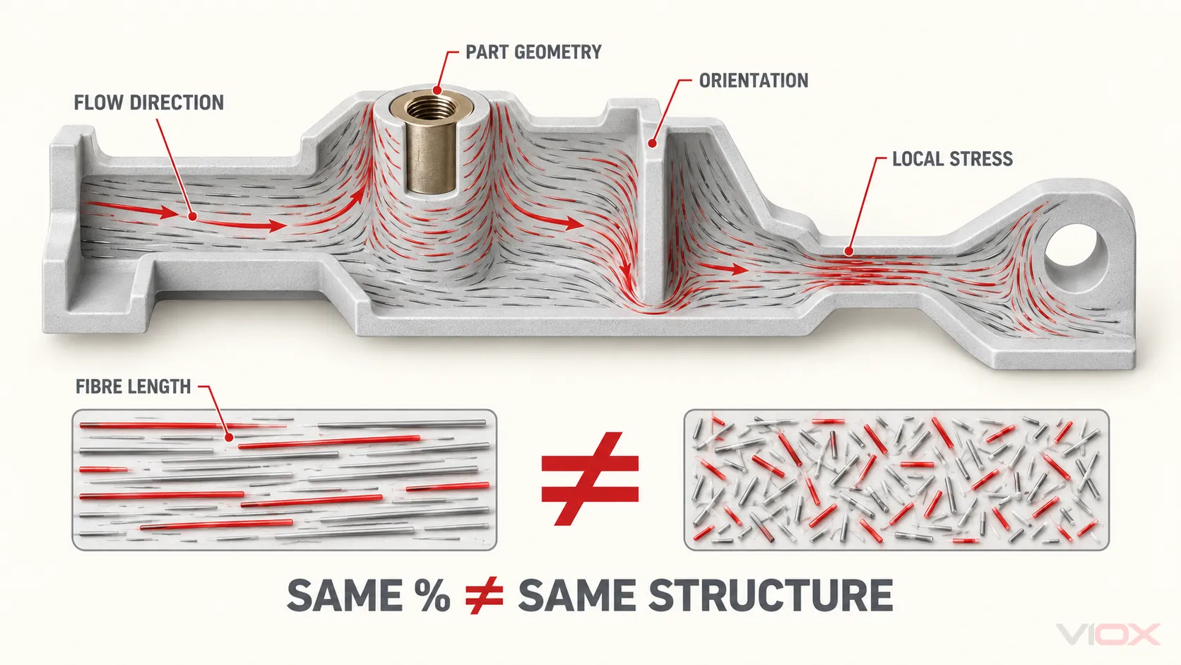
- Flow changes fibre orientation. A published glass-fibre percentage does not show how the fibres align around holes, ribs, inserts, or narrow sections.
- Orientation changes anisotropy. A molded part can show different strength and shrinkage along and across the dominant flow direction.
- The process changes defects. Inadequate venting, poor charge placement, contamination, cure variation, excessive shear, or uncontrolled insert conditions can create voids, incomplete fill, cracks, exposed fibres, distortion, or weak regions.
- Geometry changes electrical and mechanical stress. Wall thickness, radii, creepage paths, clearances, insert spacing, arc exposure, fastening load, and short-circuit forces act on the molded part—not on a flat data-sheet specimen.
This is why equal fibre content does not produce equal part performance, and why a higher data-sheet value cannot replace a drawing review or molded-part test.
Why Thermoset Compounds Are Used in Circuit Breakers
Properly specified fibre-reinforced thermoset compounds can combine electrical insulation, dimensional stability, heat resistance, flame performance, mechanical support, and moldability. That combination is valuable where the molded part must locate conductive assemblies, support a mechanism, retain inserts, separate live regions, or contribute to an enclosure around switching components.
Typical design candidates include:
- molded-case circuit breaker (MCCB) bases and covers;
- internal insulating barriers and supports;
- insert-molded terminal or conductor supports;
- arc-adjacent insulating pieces, subject to the device design and verification;
- air-circuit-breaker or switchgear structural insulation parts;
- busbar supports and standoff insulators.
These are application directions, not universal construction statements. Some breakers or subcomponents use engineering thermoplastics, other thermosets, ceramics, laminates, or combinations of materials. Miniature circuit breaker housings, for example, are not automatically BMC simply because BMC is common in some larger molded-case structures.
For the broader choice among PA66, PBT, PC, POM, PPS, and thermoset compounds, use the VIOX guide to engineering plastics for electrical components.
A Bounded SMC vs BMC Grade Comparison
GB/T 23641-2018 is the current Chinese national standard for fibre-reinforced unsaturated-polyester SMC and BMC for electrical purposes. The following extract compares two specific designations supplied in that framework: UP-SMC-25a and UP-BMC-25a.
It does not describe all SMC and BMC. The figures are grade requirements under the cited test framework, not guaranteed properties of an arbitrary commercial compound or finished breaker part.
| Property | UP-SMC-25a | UP-BMC-25a | Engineering interpretation |
|---|---|---|---|
| Glass-fibre content | 25 ± 2.5% | 25 ± 2.5% | Equal mass fraction does not establish equal fibre length, orientation, or part strength |
| Tensile modulus | ≥10,000 MPa | ≥12,500 MPa | Stiffness alone does not predict fracture resistance or impact behavior |
| Tensile stress at break | ≥60 MPa | ≥30 MPa | This selected SMC grade has the higher minimum tensile strength |
| Tensile strain at break | ≥2.0% | ≥0.5% | The selected grades have different deformation limits before fracture |
| Compressive strength | ≥170 MPa | ≥120 MPa | Relevant to clamping and support loads, but insert geometry and stress concentration still matter |
| Flexural modulus | ≥10,000 MPa | ≥10,000 MPa | The stated minimum is equal for these two grades |
| Flexural strength | ≥180 MPa | ≥90 MPa | The selected SMC grade has the higher minimum flexural strength |
| Charpy impact strength | ≥75 kJ/m² | ≥30 kJ/m² | The selected SMC grade has the higher minimum impact result |
| Deflection temperature under load | ≥240 °C | ≥220 °C | A comparative material test, not a permissible breaker operating temperature |
| Linear thermal-expansion coefficient | ≤30 × 10⁻⁶/K | ≤30 × 10⁻⁶/K | Both share the stated limit; molded-part direction and process remain relevant |
| Temperature index, TI | ≥130 | ≥130 | A material thermal-endurance indicator, not a standalone device temperature rating |
| Electric strength | ≥22 kV/mm | ≥22 kV/mm | Specimen result; finished insulation depends on thickness, geometry, interfaces, defects, and conditions |
| Relative permittivity at 100 Hz | ≤4.8 | ≤4.5 | Relevant to dielectric behavior but rarely a sole breaker-material decision |
| Dissipation factor at 100 Hz | ≤0.02 | ≤0.02 | Both share the stated maximum under the defined test |
| Proof tracking index, PTI | ≥600 | ≥600 | Indicates passing the defined tracking test voltage; it is not a system voltage rating |
| Arc resistance | ≥180 s | ≥180 s | Useful for screening similar materials; it does not reproduce a circuit-breaker interruption event |
| Flammability | Not worse than V-0 | Not worse than V-0 | Defined specimen classification; the finished product still needs its applicable evaluation |
| Oxygen index | — | ≥38% | Listed for the selected BMC grade only in this comparison |
| Glow-wire flammability index, GWFI | — | ≥960 °C at 3.0 mm | Material result at the stated thickness; do not transfer it automatically to another thickness or end product |
| Density | 1.60–2.00 g/cm³ | 1.70–2.10 g/cm³ | Influences part mass and formulation comparison, not quality by itself |
| Molding shrinkage | ≤0.14% | ≤0.14% | The material limit does not eliminate local warpage or tool/process effects |
| Water absorption | ≤0.2% | ≤0.2% | Both share the stated maximum; actual environmental performance remains part- and condition-dependent |
The striking result is not that “SMC is always better.” It is that these two 25% glass-fibre grades reach similar stated electrical limits while differing materially in several strength and impact requirements. That illustrates why electrical and mechanical evidence must be reviewed together.
For a purchase specification or compliance file, verify every value, specimen condition, and referenced test method against the organization’s controlled copy of GB/T 23641-2018 and the exact commercial-grade documentation. This table is an engineering comparison, not a substitute for the standard.
GB/T 15568-2024 covers general-purpose SMC. It can support general material context, but it should not replace the electrical-purpose grade and finished-product evidence needed for a breaker application.
What the Electrical and Heat Values Do—and Do Not—Prove
PTI and CTI address tracking behavior
IEC 60112:2025 defines methods for determining proof tracking index (PTI) and comparative tracking index (CTI) on solid insulating-material specimens or material plaques using alternating voltage. PTI is used as an acceptance and quality-control criterion; CTI is primarily used to characterize and compare materials.
A PTI result is not the material’s working voltage and does not set the creepage distance by itself. Pollution degree, material group, electric field, surface geometry, installation environment, and the applicable product or insulation-coordination requirements still matter.
GWFI is a material flammability test
IEC 60695-2-12:2021 defines the glow-wire flammability index test for material specimens. The result belongs to the tested material and specimen conditions, including thickness. End-product glow-wire evaluation and the circuit breaker’s complete fire-hazard assessment are separate questions.
Arc resistance is preliminary material differentiation
IEC 61621 describes a high-voltage, low-current arc-resistance test intended for preliminary differentiation, formulation-change detection, and quality control of dry solid insulating materials. It does not reproduce the high-current arc, gas pressure, conductive deposits, contact motion, or interruption sequence inside a circuit breaker.
Deflection temperature is not an operating-temperature rating
Deflection temperature under load is measured under defined specimen geometry, stress, and heating conditions. ISO 75-1:2020 provides the general method, while ISO 75-3:2025 addresses high-strength thermosetting laminates and long-fibre-reinforced plastics within its scope. The result is useful for comparing material behavior under the specified test; it does not authorize continuous service at that temperature.
Map the Material Direction to the Breaker Part
| Part or design condition | Plausible starting direction | Why | Evidence still required |
|---|---|---|---|
| Broad, load-bearing insulating panel or structural barrier | SMC | Larger sheet charge and structural reinforcement can suit broad compression-molded forms | Grade data, flow/orientation review, molded-part dimensions, mechanical and electrical verification |
| MCCB base or cover with ribs, bosses, inserts, and three-dimensional cavities | BMC/DMC or another qualified thermoset | Bulk charge and compatible molding routes can fill detailed, thicker geometry | Exact grade, insert process, cure control, dimensional checks, part tests, and breaker-level verification |
| Compact insert-molded insulating support | BMC/DMC or qualified engineering thermoplastic | Detailed flow around embedded hardware may control the choice | Pull-out/torque or load evidence as applicable, dielectric and tracking requirements, section quality, change control |
| Busbar support or standoff | BMC/DMC, SMC, cast resin, or another specified system | Electrical insulation and mechanical support must be solved together | Drawing, inserts, rated mechanical loads, environment, dielectric evidence, and assembly verification |
| Thin precision mechanism part away from high-stress insulation duty | Often an engineering thermoplastic rather than SMC/BMC | Fine features, snap fits, friction, and molding precision may dominate | Exact polymer grade, moisture/heat behavior, flame and electrical requirements, endurance |
| Arc-adjacent insulating component | Product-specific material system | Arc exposure, deposits, gas flow, geometry, and interruption design dominate | Exact breaker design evidence; never select from generic arc-resistance seconds alone |
The VIOX MCCB product family provides the device context, while the busbar insulator product family shows another application where molded insulation and structural support must be evaluated together. Product availability, exact material, ratings, and conformity evidence must be confirmed for the relevant model.
What Buyers and Engineers Should Request
A defensible approval package connects five identities:
part drawing → material designation → molded lot → test evidence → finished breaker or assembly
Request at least:
- the complete compound designation, resin family, reinforcement content, color, and approved supplier;
- the controlled material data sheet and applicable specification or grade;
- test methods, specimen thickness, conditioning, direction, and acceptance values for consequential properties;
- a drawing that identifies critical wall thicknesses, inserts, radii, creepage paths, barriers, and load points;
- molding-process controls for charge or feed identity, cure, tool, cavities, inserts, and nonconforming parts;
- lot traceability from incoming compound through the molded part and finished device;
- change-control rules covering resin, filler, fibre, additives, pigment, supplier, tooling, process, and production site;
- molded-part inspection and verification appropriate to the function;
- finished-breaker or assembly evidence under the applicable product standard and target-market route.
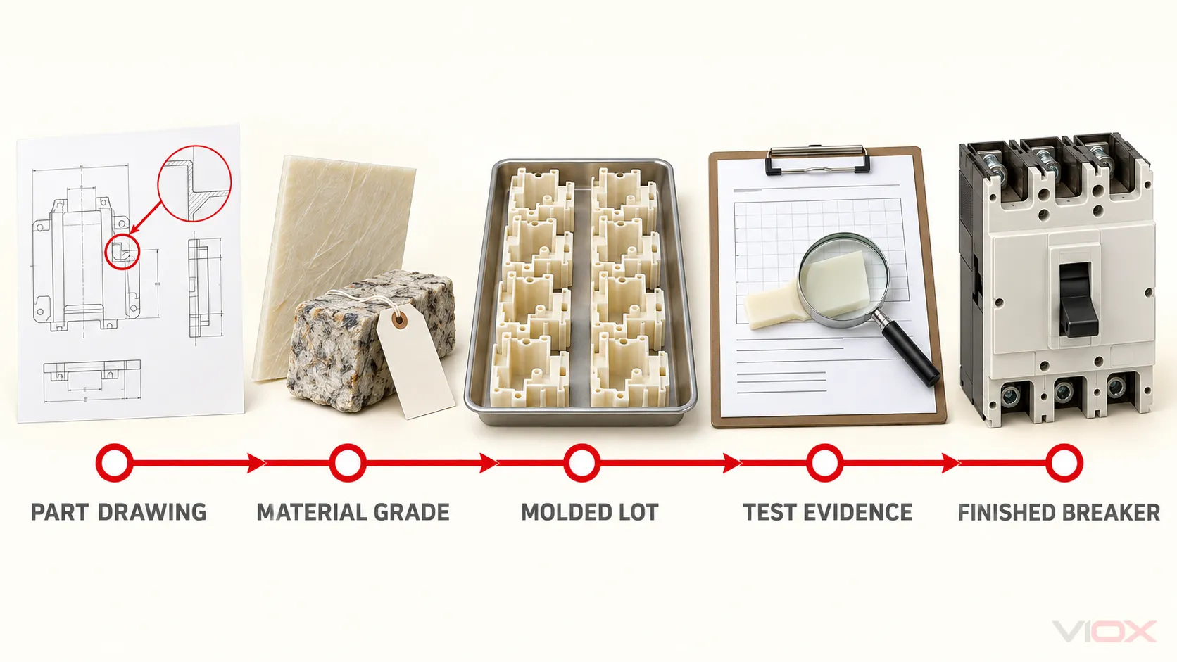
A certificate for a resin plant, an ISO 9001 certificate, or a material data sheet can support one link. None proves the whole chain. The VIOX article on quality assurance in MCB manufacturing explains the same identity and change-control principle at finished-device level.
Frequently Asked Questions
Is DMC the same as BMC?
Sometimes the terms are used interchangeably in trade, but they should not be assumed identical in a technical specification. ISO 8606:2025 recognizes BMC and DMC as types of preimpregnated molding product. Confirm how the supplier defines the term and obtain the complete grade specification.
Is SMC always stronger than BMC?
No. Conventional SMC often uses a fibre architecture that supports higher structural and impact performance, but the result depends on the compared grades, resin and filler system, fibre content and orientation, molding process, and specimen or part geometry. The UP-SMC-25a versus UP-BMC-25a table is a comparison of two grades, not a universal law.
Why is BMC used for MCCB cases and covers?
BMC can combine thermoset insulation behavior with flow into ribs, bosses, insert regions, and other detailed three-dimensional features. Whether it is suitable depends on the exact formulation, part design, molding controls, and breaker-level verification.
Does PTI 600 mean a material can be used at 600 V?
No. PTI is a result from a defined surface-tracking test and is not a working-voltage rating. The applicable product design must also address creepage and clearance, pollution, geometry, environment, and product-standard requirements.
Can material test data prove the breaking capacity of an MCCB?
No. Breaking capacity is a finished-device performance involving the contacts, mechanism, current path, arc-control system, enclosure, insulation, terminals, and tested construction. Material data supports design and quality control but cannot establish a breaker’s interrupting rating by itself.
Final Engineering Rule
Do not select SMC, BMC, or DMC by acronym. Select a defined compound grade and molding route for a defined part geometry, then verify the molded part and the complete breaker or assembly at the appropriate level.
SMC is often the better starting point for broad structural insulation pieces. BMC/DMC are often the better starting point for compact, detailed, and insert-rich molded parts. The final decision belongs to the evidence chain—not to the material name.