On this page
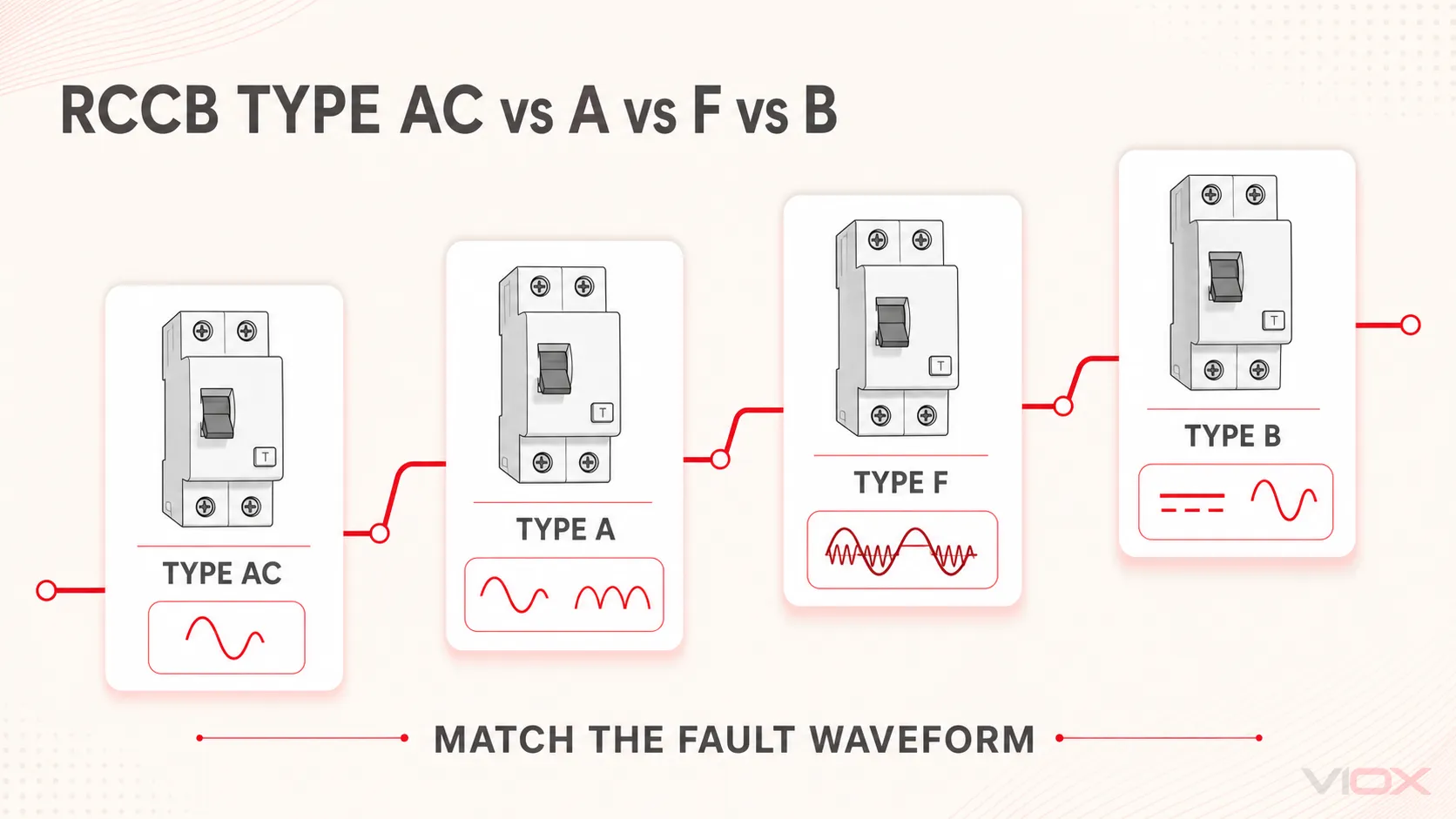
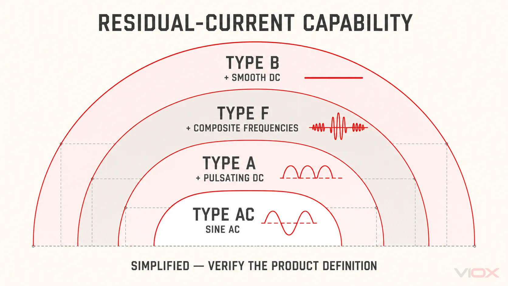
The difference between RCCB Type AC, Type A, Type F, and Type B is the residual-current waveform the device is designed to detect and respond to. In simplified terms, Type AC covers sinusoidal AC residual current; Type A adds pulsating DC; Type F adds specified composite residual currents associated with certain single-phase frequency-converter loads; and Type B adds smooth DC plus a broader defined frequency range.
This is a capability comparison—not a rule that every electronic load needs Type B. Select the type from the connected equipment’s possible fault-current waveform, manufacturer instructions, applicable installation rules, and the exact RCCB documentation.
| RCCB type | Residual-current capability, simplified | Load condition that may point to it | Do not proceed when |
|---|---|---|---|
| Type AC | Sinusoidal alternating residual current | Basic AC load with no rectifying or inverter behavior, where Type AC is permitted | Electronic topology is unknown, the load can produce pulsating DC, or local rules restrict Type AC |
| Type A | Type AC capability plus pulsating DC residual current | Many single-phase electronic loads with rectifier stages | Smooth DC or composite mixed-frequency residual current can occur and no other documented protection addresses it |
| Type F | Type A capability plus specified composite residual currents from certain single-phase frequency converters | Some single-phase variable-speed appliances and inverter-driven equipment | The load is three-phase, can produce smooth DC, or the manufacturer does not support Type F |
| Type B | Type F-related capability plus smooth DC and defined sinusoidal residual currents up to 1,000 Hz within IEC 62423 | Some three-phase converters, Variable Frequency Drives (VFDs), photovoltaic inverters, Uninterruptible Power Supplies (UPSs), EV charging and similar power-electronic systems | The application is being inferred from a category name instead of exact equipment and system documents |
What Does the RCCB Type Letter Describe?
An RCCB is a Residual Current Circuit Breaker without integral overcurrent protection. Its sensing system monitors the vector sum of the live conductors passing through it and operates when the residual current meets its defined conditions. The What Is an RCCB hub explains that operating boundary in detail.
The type letter describes waveform sensitivity. It does not describe:
- rated residual operating current
IΔn, such as 30 mA, 100 mA, or 300 mA; - rated current
In, such as 40 A or 63 A; - the number of poles;
- instantaneous or selective/time-delayed behavior;
- the breaking or conditional short-circuit arrangement; or
- an MCB’s B, C, or D overcurrent trip curve.
These fields are separate. A “Type B 63 A 30 mA RCCB,” for example, combines a residual-current waveform type, a current-carrying rating, and a residual operating rating. None of those fields replaces the others. Use the complete RCCB selection guide when the task extends beyond waveform type.
The Detection-Capability Ladder
IEC 62423:2009 specifies additional requirements and tests for Type F and Type B Residual Current Devices (RCDs), used together with the relevant base RCCB or RCBO standard. The IEC describes Type F requirements as additions to Type A requirements. It describes Type B devices as able to respond to sinusoidal AC residual currents up to 1,000 Hz, pulsating DC, and smooth DC residual currents.
A useful simplified ladder is:
Type AC → sinusoidal AC
Type A  → Type AC capability + pulsating DC
Type F  → Type A capability + specified composite frequencies
Type B  → broader frequency capability + smooth DC
This ladder does not prove that a broader type is automatically the correct installed device. Rated voltage, frequency, In, IΔn, poles, time characteristic, supply dependence, upstream/downstream coordination, manufacturer restrictions, and national installation requirements still apply.
Type AC RCCB
Type AC RCCBs are intended to respond to sinusoidal alternating residual current. That boundary can fit a genuinely simple AC load, but modern equipment often contains diode bridges, switch-mode power supplies, electronic controls, or inverter stages that can change the fault-current waveform.
Therefore, “residential,” “lighting,” or “heating” is not enough information to select Type AC. The actual connected equipment and applicable rules must confirm that only the relevant sinusoidal AC residual-current condition needs to be considered.
Choose Type AC only after verifying:
- the load topology does not introduce a residual-current waveform outside Type AC capability;
- the equipment instructions do not require another RCD type;
- the destination-market installation rules permit Type AC for the circuit; and
- the exact RCCB has the required product documentation.
Type A RCCB
Type A adds response to pulsating DC residual current as well as sinusoidal AC residual current. Pulsating DC can arise from single-phase electronic loads using rectifier or phase-control circuits. This makes Type A relevant to many modern appliances and electronic circuits.
However, Type A is not a universal “electronic-load RCCB.” Its classification does not give it the smooth-DC capability of Type B or the specified composite-frequency behavior of Type F. The equipment topology still determines whether Type A is sufficient.
A Type A candidate becomes unresolved when:
- the manufacturer specifies Type F or Type B;
- the equipment can create composite mixed-frequency residual current;
- smooth DC residual current can occur;
- a separate DC-detection arrangement is claimed but not documented; or
- system-level DC leakage could affect upstream residual-current devices.
Type F RCCB
Type F was introduced for specified composite residual currents associated with certain single-phase frequency-converter loads. IEC 62423 identifies Type F RCCBs for installations where a frequency inverter is supplied between phase and neutral, or between phase and an earthed middle conductor, and where composite residual currents may occur.
This makes Type F a candidate for some single-phase variable-speed appliances, heat pumps, air-conditioning equipment, washing machines, pumps, and similar inverter-driven loads—but only when the equipment instructions and circuit topology support that choice.
Three boundaries matter:
- Type F is not defined by the product name. Not every heat pump, motor, or variable-speed appliance has the same converter topology.
- Type F is not Type B. It does not provide the same smooth-DC residual-current capability.
- Type F is not simply an anti-nuisance-trip accessory. Disturbance immunity may be relevant to particular products, but the type selection must first match the possible fault-current waveform.
Type B RCCB
Type B covers smooth DC residual current in addition to sinusoidal AC, pulsating DC, and defined frequency components within its product scope. It is evaluated for applications where conversion topology can produce residual currents that Type AC, Type A, or Type F is not designed to handle.
Potential contexts include three-phase frequency converters, VFD-fed equipment, PV inverters, UPS systems, EV charging, and certain industrial or medical equipment. These are screening categories, not automatic prescriptions. A specific inverter may incorporate monitoring or protective functions that change the required external RCD, while another device in the same category may explicitly require Type B.
Type B is not a universal upgrade because the full design still controls:
- whether the exact load can produce smooth DC residual current;
- normal DC leakage passing through upstream or parallel RCDs;
- upstream/downstream selectivity and coordination;
- any application-specific DC detection arrangement;
- product voltage, frequency, pole, and time-characteristic limits; and
- the applicable installation rules and equipment instructions.
For EV charging, use the dedicated EV charger RCCB selection guide rather than applying a blanket Type B rule.
Load Topology to RCCB Type Decision Matrix
The safest preliminary selection starts with the power-conversion circuit, not the appliance label.
| Load or conversion topology | Possible residual-current behavior | Preliminary type to investigate | Required evidence | Stop condition |
|---|---|---|---|---|
| Simple AC load without electronic conversion | Sinusoidal AC | Type AC, where permitted | Equipment circuit information and installation rules | Any rectifier, electronic control, or non-sinusoidal fault-current path is present or unknown |
| Single-phase load with rectifier or phase control | Sinusoidal AC plus pulsating DC | Type A | Equipment manual and residual-current requirement | Composite frequencies or smooth DC are possible |
| Certain single-phase inverter between phase and neutral | Pulsating DC plus composite frequencies | Type F | Manufacturer-specified RCD type and converter topology | Three-phase conversion, smooth DC, or unsupported Type F application |
| Single-phase conversion with smoothing that can produce smooth DC | Smooth DC may occur | Type B or another explicitly documented protection architecture | Exact manufacturer protective-device instruction | The DC function or upstream RCD relationship is unspecified |
| Three-phase rectifier or frequency converter | Smooth DC and frequency components may occur | Type B | Converter manual, circuit diagram, system coordination data | Selection is based only on “VFD” or motor nameplate language |
| EV charger with documented 6 mA Residual Direct Current Detecting Device (RDC-DD) | DC condition handled by a defined EV protection function | Type A or Type F may be possible if instructed and permitted | Exact EVSE/RDC-DD evidence and upstream RCD requirement | “6mA protection” is only a marketing statement |
| EV charger without suitable documented DC detection | Smooth DC condition remains for external protection | Type B strategy to evaluate | EVSE manual, installation rules, exact Type B documents | Circuit architecture or manufacturer requirement is unresolved |
“Preliminary type to investigate” is deliberate wording. The table cannot replace the equipment manufacturer’s instructions or applicable installation rules.
Evidence-First Selection Workflow
1. Identify the exact equipment and supply topology
Record whether the load is single-phase or three-phase, how power conversion is arranged, whether a neutral is present, and whether power can flow in more than one direction. A family name such as “inverter,” “EV charger,” or “heat pump” is not a circuit diagram.
2. Determine the possible residual-current waveform
Use the equipment manual, converter documentation, and applicable design information to identify sinusoidal AC, pulsating DC, composite-frequency, and smooth-DC conditions. If the waveform evidence is missing, record the type as unresolved rather than guessing.
3. Match the waveform to the product definition
Screen Type AC, A, F, or B using the fixed comparison basis above. Then verify that the exact RCCB documentation identifies the required type and applicable standards. IEC 61008-1:2024 provides general rules for RCCBs without integral overcurrent protection; IEC 62423 adds Type F and Type B requirements within its scope.
4. Verify the complete protection architecture
Confirm manufacturer instructions, destination-market rules, upstream residual-current devices, any separate DC detection, and the external MCB or fuse needed for overcurrent protection. The type letter answers only one part of the design.
The final record should state:
Connected equipment and exact model:
Supply and converter topology:
Possible residual-current waveform:
Manufacturer-required RCD type:
Selected RCCB type:
Applicable product standard and exact evidence:
Separate DC-detection arrangement, if any:
Upstream/downstream RCD coordination requirement:
Applicable installation rules:
Unresolved items that prevent model selection: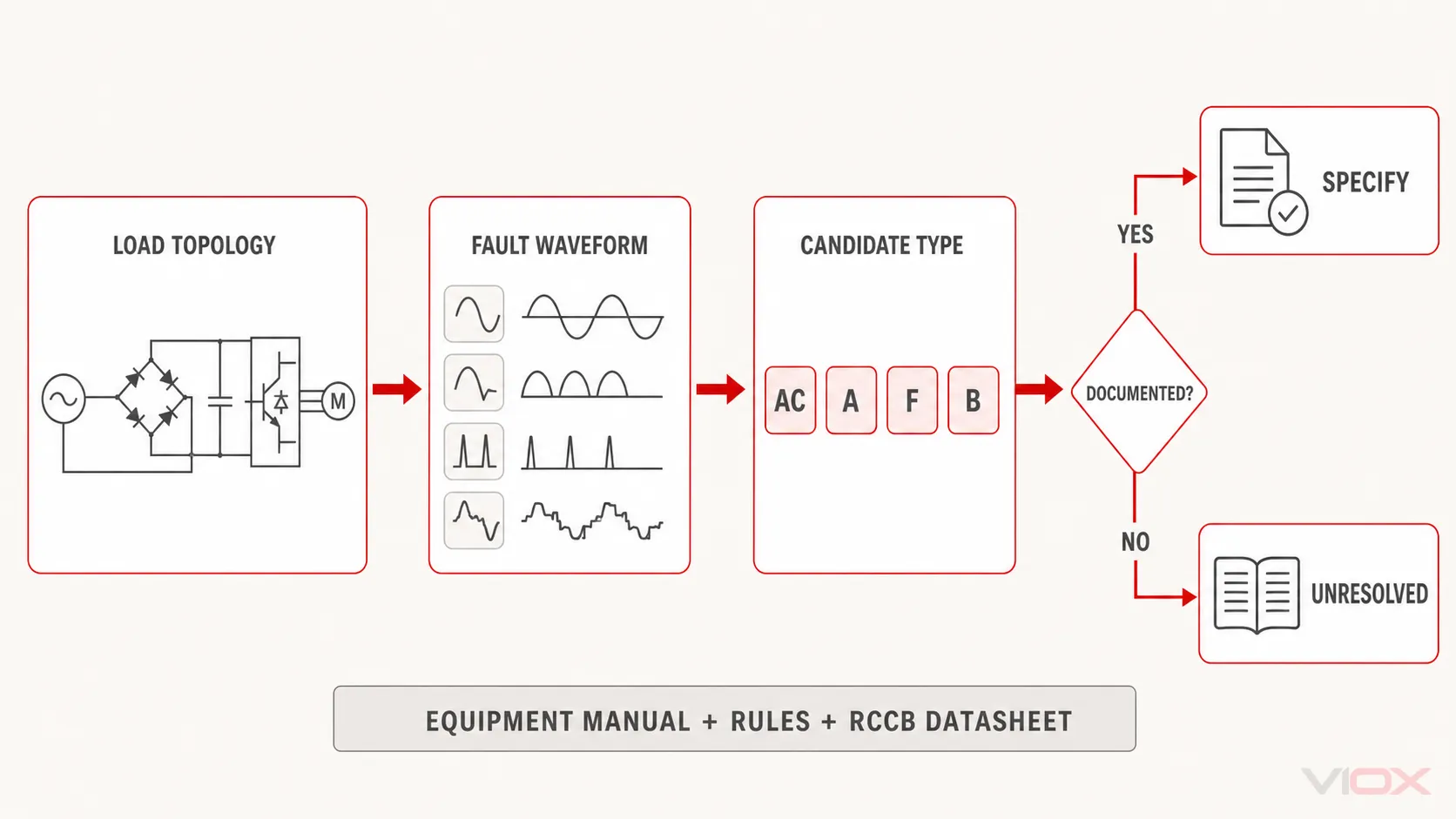
RCCB Type vs RCBO Type
Type AC, A, F, and B describe residual-current response and can apply to both RCCBs and Residual Current Breakers with Overcurrent Protection (RCBOs) within their relevant product standards. The waveform comparison is therefore related, but the final device-selection tasks are not identical.
An RCCB needs associated overload and short-circuit protection. An RCBO integrates those functions, so RCBO selection must also define rated current, overcurrent trip characteristic, and breaking capacity. Use the separate RCBO Type AC vs A vs F vs B guide when the circuit requires an RCBO rather than an RCCB.
Focused RCCB Type Questions
Is Type A RCCB better than Type AC?
Type A has broader residual-current waveform capability because it adds pulsating DC response. That does not make it automatically correct for every circuit: confirm the equipment behavior, product documents, and local requirements. Where modern electronic loads are present, Type AC may be insufficient or restricted.
Can Type F RCCB detect smooth DC residual current?
Type F is intended for specified composite residual currents associated with certain single-phase frequency-converter loads. It should not be treated as having the smooth-DC capability of Type B.
Can a Type B RCCB replace Type F?
Type B has broader waveform capability within IEC 62423, but substitution is not decided by waveform breadth alone. Verify the equipment instruction, exact product ratings, time characteristic, supply conditions, upstream coordination, and applicable installation rules before substituting devices.
Is a Type B RCCB the same as a B-curve MCB?
No. “Type B” on an RCCB describes residual-current waveform capability. “B curve” on an MCB or RCBO describes the instantaneous overcurrent trip characteristic. They are independent classifications.
Sources Reviewed
- IEC 61008-1:2024 — RCCBs without integral overcurrent protection
- IEC 62423:2009 — Type F and Type B RCD requirements
- Schneider Electrical Installation Guide — Types of RCDs
- ABB — Answers on regulations, application fields and installation methods for RCCBs
- ABB — RCD Type Selection Guide
After the waveform type and remaining specification fields are documented, compare the VIOX RCCB range and request exact model datasheets, certificates, and destination-market documents from [email protected].