このページについて
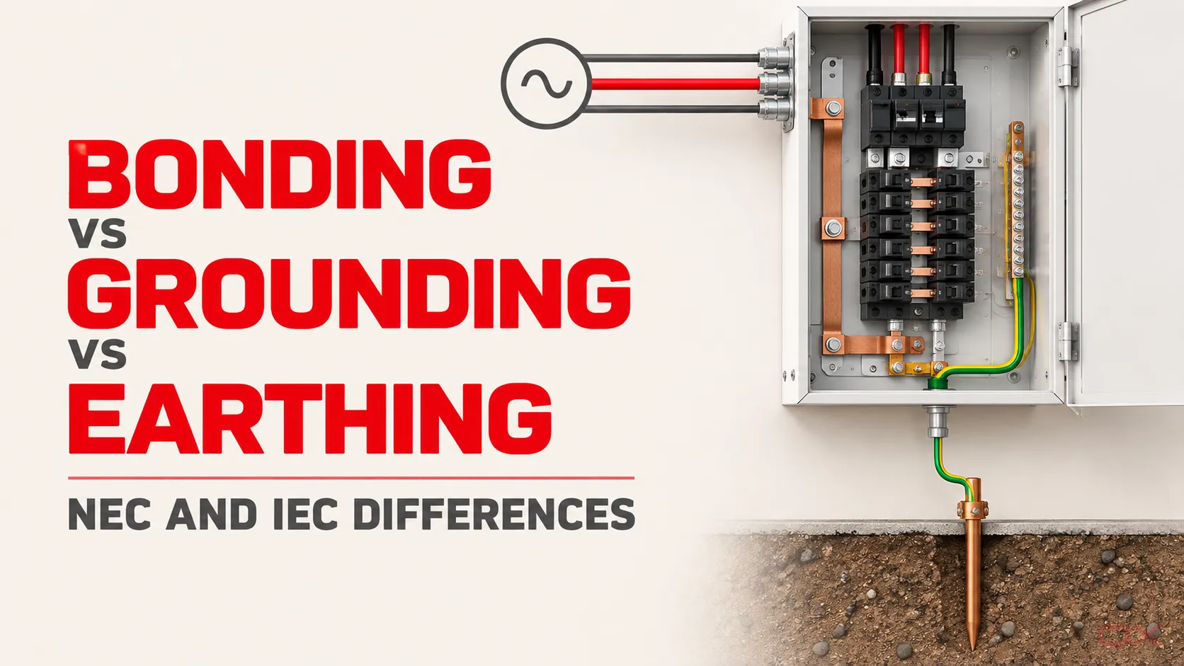
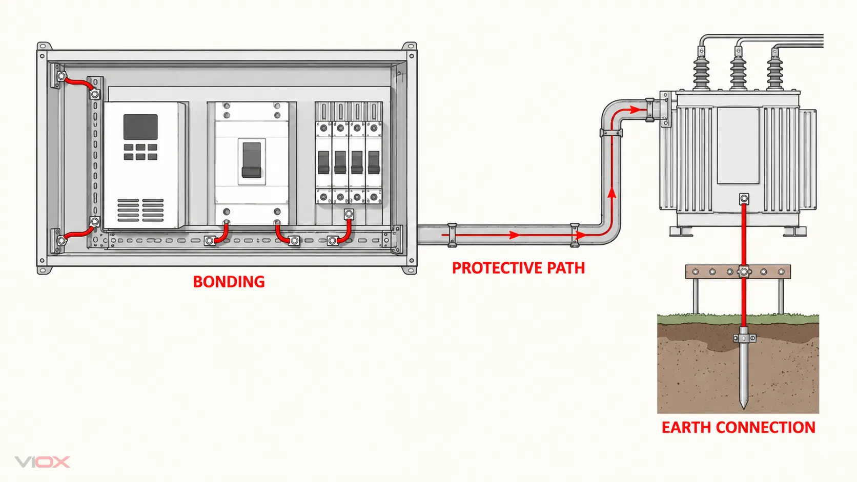
Bonding, grounding, and earthing describe related but different electrical functions. Bonding joins conductive parts to maintain electrical continuity and limit dangerous potential differences. Grounding is the dominant US National Electrical Code (NEC) vocabulary for several system, equipment, and earth-related connections. Earthing is the dominant International Electrotechnical Commission (IEC) vocabulary for connections to earth and the earthing arrangements built around them.
Grounding and earthing are often regional counterparts, but they are not safe word-for-word substitutes. A specification must identify the function: connection to an earth electrode, protective fault-current path, equipotential bonding, grounded system point, or neutral function.
安全上の境界: This is a terminology and system-interpretation guide, not a wiring procedure. Grounding and earthing requirements depend on the supply, earthing arrangement, protection method, adopted code, equipment instructions, and local authority. Design, inspection, testing, and alteration should be performed by qualified persons.
The Three Terms at a Glance
| 期間 | Functional meaning | Typical NEC/US usage | Typical IEC/international usage |
|---|---|---|---|
| 接合 | Electrically connects conductive parts to establish continuity and control potential differences | Equipment bonding, main bonding jumper, system bonding jumper | Protective equipotential bonding, protective bonding conductor |
| 接地 | US umbrella language for connecting systems or equipment to earth and for conductors participating in the equipment fault-current path | System grounding, equipment grounding conductor, grounding electrode conductor | 接地 may appear in translations or local practice, but IEC documents normally use earthing 用語と整合しています。 |
| 接地 | Connects a system, installation, or equipment to earth through an earthing arrangement | Often used informally as a synonym for grounding | Earth electrode, earthing conductor, main earthing terminal, protective earthing |
The quickest practical rule is:
- Bonding asks: which conductive parts must be electrically connected?
- Grounding or earthing asks: what is connected to earth, where, and for what system function?
- Fault protection asks: what complete path and protective device will disconnect the supply under the defined fault?
Those questions interact, but none can replace the others.
Why NEC and IEC Terms Do Not Translate One-for-One
The NEC and IEC frameworks describe many of the same physical objectives: controlling touch voltage, creating reliable protective paths, connecting a system to earth, and achieving automatic disconnection when required. They divide and name those functions differently.
In US practice, the word 接地 appears in names that do not mean “send normal current into the soil.” An equipment grounding conductor (EGC), for example, forms part of a conductive fault-current path back toward the source bonding point. The NEC principle is that earth itself is not the effective ground-fault current path used to operate an overcurrent protective device.
IEC terminology more visibly separates earthing, protective conductorsそして protective equipotential bonding. IEC 60050-195 establishes the vocabulary for earthing and protection against electric shock, while IEC 60364-5-54 addresses earthing arrangements, protective conductors, and protective bonding conductors.
The result is a functional crosswalk, not a translation dictionary.
NEC-to-IEC Function Crosswalk
| 機能 | NEC/US term | Closest IEC term | Mapping quality | Critical qualification |
|---|---|---|---|---|
| Connect exposed conductive equipment parts into the protective fault-current path | 機器接地導体 (EGC) | Protective conductor, commonly PE where it provides protective earthing | Close, not exact | Permitted conductor forms, sizing, identification, source relationship, and disconnection rules differ by system and jurisdiction |
| Connect the electrical system to the grounding electrode system | 接地電極導体 (GEC) | Earthing conductor | Close | Do not confuse either conductor with the complete equipment fault-current path |
| Connect conductive parts for safety and continuity | Bonding conductor or bonding jumper | Protective bonding conductor | Close | The parts connected and required conductor properties depend on the applicable rule and installation boundary |
| Establish the service or derived-system connection between the grounded conductor and equipment-bonding network | 主ボンディングジャンパまたはシステムボンディングジャンパ | No single universal one-for-one label | 部分的 | IEC implementation depends on the TN, TT, or IT arrangement and the source/distribution architecture |
| Carry normal line-to-neutral load current and be intentionally connected to ground/earth at an approved point | Grounded conductor; often, but not always, the neutral conductor | Neutral conductor, where a neutral point and function exist | 部分的 | 接地側導体 そして 中性 are not universal synonyms |
| Combine protective and neutral functions in one conductor | No ordinary downstream equivalent to a separated neutral plus EGC | PEN導体 | Unsafe without system context | A PEN belongs to defined TN-C or TN-C-S architecture and must not be treated as a generic neutral or PE |
| Direct conductive connection with the general mass of earth | Grounding electrode | Earth electrode | Close | Electrode construction, qualification, testing, and its role in fault protection remain code- and system-specific |
| Common termination point for protective and earthing functions | Grounding/bonding terminal or bar, depending on equipment boundary | Main earthing terminal or main earthing busbar | 部分的 | A physical bar’s name does not prove its permitted neutral, PE, bonding, or electrode function |
“PE equals ground” is useful shorthand—but incomplete
On an IEC drawing, PE identifies a protective conductor function. On a US drawing, an EGC may perform a closely related protective function. Translating both simply as “ground wire” hides important differences in conductor identity, permitted wiring methods, source bonding, and system architecture.
For component-level panel interpretation, the separate VIOX guide to neutral bars versus grounding bars explains why the physical termination points cannot be identified by colour or nickname alone.
Bonding: Continuity and Potential Control
Bonding connects conductive parts so they do not remain electrically isolated from the protective system or develop an uncontrolled potential difference. Depending on the installation, the bonded network can include equipment enclosures, metal raceways, cable armour, structural metal, conductive piping, and designated terminals or bars.
Under NEC logic, equipment bonding also helps create the low-impedance circuit needed for fault current to return to the source and operate the protective device. OSHA’s publicly accessible rules require bonding conductors used for continuity to carry the fault current that may be imposed, and metal enclosures or raceways serving the protective path must be effectively bonded.
IEC language commonly uses protective equipotential bonding. The objective is not to promise that every connected point has exactly zero voltage difference under every transient or fault. It is to establish the protective connections required to limit hazardous differences of potential within the designed protection system.
Bonding therefore does not automatically mean:
- connecting every metal object indiscriminately;
- connecting neutral and PE at every distribution board;
- installing an additional earth electrode;
- providing lightning protection by itself; or
- satisfying fault protection without a verified conductor path and protective device.
Grounding in NEC Usage
NEC Article 250 uses grounding and bonding across several distinct functions. Keeping them separate prevents the common mistake of treating every green conductor, bonding screw, and ground rod as interchangeable.
Electrical system grounding
A system conductor or point is intentionally connected to earth to establish the system’s relationship to ground, stabilize voltage to earth under normal conditions, and address imposed voltages under defined conditions. The actual connection point depends on whether the source is service-supplied or separately derived and on the applicable system rules.
Equipment grounding and bonding
Exposed normally non-current-carrying conductive parts are connected into an effective protective network. If a line conductor contacts a bonded enclosure, the intended path returns fault current through conductive equipment-grounding and bonding paths toward the source—not primarily through soil.
接地電極システム
The grounding electrode system connects the premises electrical system to qualifying electrodes in contact with earth. It has important voltage-reference and imposed-voltage functions, but a rod alone is not a substitute for a missing EGC or bonding connection.
VIOX NEC panel grounding and bonding guide covers service equipment, downstream panels, grounding electrodes, and bonding-point placement in greater depth. Those installation decisions intentionally remain outside this terminology page.
Earthing in IEC Usage
IEC uses 接地構成 to describe the relationship among the power-system source, earth, exposed conductive parts, and protective conductors. The familiar TN, TT, and IT letters encode those relationships rather than identifying one universal “earth wire.”
Earth electrode and earthing conductor
An earth electrode establishes conductive contact with earth. The earthing conductor connects the electrode to the earthing system, commonly through a main earthing terminal or busbar. It does not automatically perform every PE, neutral, or bonding function in the installation.
Protective conductor and PE
A protective conductor is provided for safety functions. PE is the designation commonly used where the conductor provides protective earthing. Its route and role depend on the earthing arrangement and protective measure.
Protective bonding conductor
A protective bonding conductor connects specified conductive parts for protective equipotential bonding. It should not be renamed neutral merely because it terminates near the neutral bar, and it should not normally carry load current.
For the architecture behind these terms, see TN, TT, and IT earthing systems. That guide owns the system-selection and fault-behaviour task; this page owns terminology translation.
The Fault-Path Difference That Changes the Answer
A widely repeated US statement says that earth is not an effective ground-fault current path. That is correct within its NEC performance context, but it must not be turned into the global claim that earth is never part of a protective fault loop.
| アーキテクチャ | Simplified fault-current path | Usual protective implication | 想定すべきでない事項 |
|---|---|---|---|
| NEC grounded system with an EGC | Line fault → bonded enclosure → EGC/bonding path → source bonding point → source winding | The metallic path is designed to permit sufficient fault current for the applicable protective device to operate | A remote rod can replace a missing EGC |
| IEC TN system | Line fault → exposed conductive part → PE or PEN path → earthed source point → source winding | The metallic protective path and loop impedance are central to automatic disconnection | Every TN variant permits the same neutral/PE treatment |
| IEC TT system | Line fault → exposed conductive part → installation electrode → earth → source electrode → source winding | Earth electrodes form part of the fault loop; residual-current protection is commonly necessary because loop impedance may limit current | A normal overcurrent device will always disconnect fast enough |
| IEC IT system, first fault | Depends on source isolation or impedance, distributed capacitance, earthing, and exposed-part connections | Monitoring and the system-specific response to first and subsequent faults are central | First-fault behaviour can be inferred from TN or TT rules |
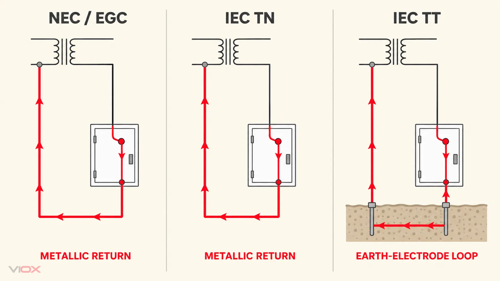
This distinction explains why a technically correct sentence can become unsafe when copied across standards. Always identify the earthing arrangement and protective measure before judging the conductor or electrode path.
Neutral, Grounded Conductor, PE, and PEN Are Not Interchangeable
Terminology errors often become wiring errors at the neutral boundary.
Neutral is a circuit function
A neutral conductor is connected to a neutral point and can carry operating current. Not every grounded conductor is necessarily a neutral, and not every AC system distributes a neutral.
PE is a protective function
A PE conductor is intended for protective purposes, not as a normal load-current return. The same practical boundary applies to a US EGC: normal neutral current should not be placed on downstream equipment-grounding and bonded metal paths by an unintended connection.
PEN combines functions only where the architecture permits it
An IEC PEN conductor combines protective earthing and neutral functions in a defined portion of a TN system. Once those functions are separated into PE and N, they cannot be casually recombined downstream. A drawing marked PEN therefore carries much more system information than the word “ground.”
Earth bar and neutral bar describe intended roles, not appearance
A bar’s material or mounting position does not establish whether it is intended for neutral, PE, bonding, or electrode connections. Confirm its insulation from or bonding to the enclosure, terminal ratings, approved conductor use, source boundary, and the applicable design. VIOX アースバー そして ニュートラル・バー pages show the component categories, but component selection does not determine the system architecture.
How to Interpret a Drawing or Specification
Use this function-first sequence when NEC and IEC language appear in the same project.
- Identify the governing document. Record the adopted code or standard, edition, national amendments, project specification, and approval authority.
- Identify the source and earthing arrangement. Determine whether the system is service-supplied or separately derived and whether its architecture is TN, TT, IT, or another defined arrangement.
- Trace normal current. Mark line, grounded conductor, neutral, midpoint, and any conductor intended to carry operating current.
- Trace the protective metallic path. Follow EGC, PE, PEN where permitted, bonding jumpers, enclosures, raceways, and source bonding connections.
- Trace the earth-electrode connection. Identify electrodes, GEC or earthing conductor, main earthing terminal, and the point where this subsystem connects to the electrical system.
- Identify the automatic-disconnection method. Check the expected fault loop, overcurrent protection, residual-current protection, monitoring, and required disconnection performance.
- Translate by function, not colour or abbreviation. Label a cross-market term as a closest counterpart and record the remaining differences.
- Verify the exact equipment instructions. Confirm terminal purpose, permitted conductors, bonding provisions, neutral treatment, and installation conditions for the actual equipment.
For imported machines or panels, a useful specification note is:
Supplier shall identify every N, PE, PEN, EGC, bonding, earthing-conductor, and earth-electrode connection by electrical function and governing standard. Similar terminology shall not be treated as proof of interchangeability. Provide the source and earthing arrangement, protection concept, conductor identification, and approved single-line diagram.
Common Translation Failures
| Statement | Why it is unsafe or incomplete | Better interpretation |
|---|---|---|
| “Ground and earth are exactly the same.” | Regional words may overlap, but system and conductor terms do not map exactly | Identify the earth connection, protective path, and governing framework |
| “PE is just the IEC name for a ground rod wire.” | PE is a protective-conductor designation; the earthing conductor to an electrode is a distinct function | Trace PE and the earthing conductor separately |
| “The neutral is grounded, so it can use the ground bar.” | The permitted N-to-protective-system connection depends on the source and bonding boundary | Identify the approved bonding point and keep downstream functions separated where required |
| “A second rod will clear the fault.” | In common NEC and TN paths, the protective device relies on a sufficiently low-impedance return toward the source | Repair and verify the complete EGC/PE/bonding path |
| “Earth never carries fault current.” | That statement ignores TT and other earth-return conditions | Identify the earthing arrangement and protection method |
| “PEN means neutral plus a spare earth wire.” | PEN is one conductor with combined functions under defined conditions | Apply the specific TN-C/TN-C-S rules and separation boundary |
| “Bonding and earthing eliminate the need for RCD/GFCI or SPD protection.” | These measures address different hazards and current paths | Coordinate each required protection layer independently |
The separate VIOX guide to RCD/GFCI, grounding, and surge protection explains why these functions may coexist without being substitutes. For lightning-related bonding and earthing boundaries, use the 雷保護システムガイド.
The Specification Rule to Keep
Do not approve or reject a conductor because a drawing calls it “ground” or “earth.” Determine what it connects, whether it carries normal current, how it participates in fault protection, where the source bonding point is, what role the earth electrode plays, and which code or standard governs the installation.
The safe cross-market translation is not:
ground = earth = PE = neutral
それは:
term + electrical function + system boundary + governing standard + verified fault path
主要な出典
- IEC 60050-195:2021 — International Electrotechnical Vocabulary: Earthing and protection against electric shock
- IEC 60364-5-54 — Earthing arrangements and protective conductors
- IEC 60364-4-41 — Protection against electric shock
- NFPA 70 National Electrical Code editions in NFPA LiNK
- NFPA public Article 250 development material: grounding, bonding, and effective ground-fault current path
- OSHA 1910.304 — Wiring design and protection
- OSHA 1910.305 — Wiring methods, components, and equipment
- OSHA 1926.404 — Wiring design and protection
Standards, codes, national adoptions, and local requirements change. Confirm the adopted edition, system design, equipment documentation, and approval requirements for the actual project.