On this page
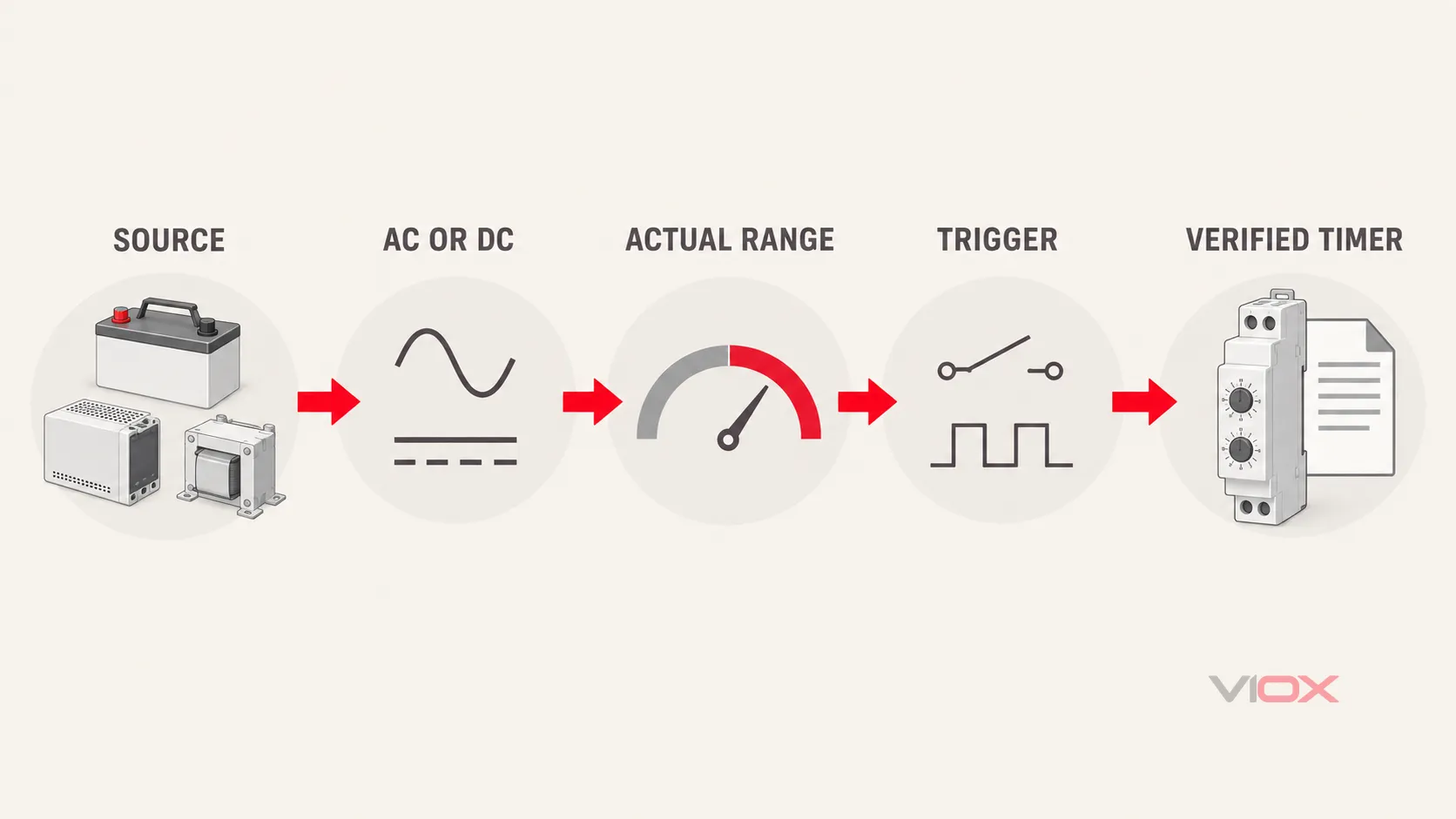
Choose a timer relay from the voltage that will actually be applied to its supply terminals, not from the voltage of the load being switched. Before ordering, verify whether that supply is AC or DC, its normal and worst-case voltage range, AC frequency or DC polarity requirements, and whether the timer uses a separate trigger input. Check the output-contact rating as a different specification.
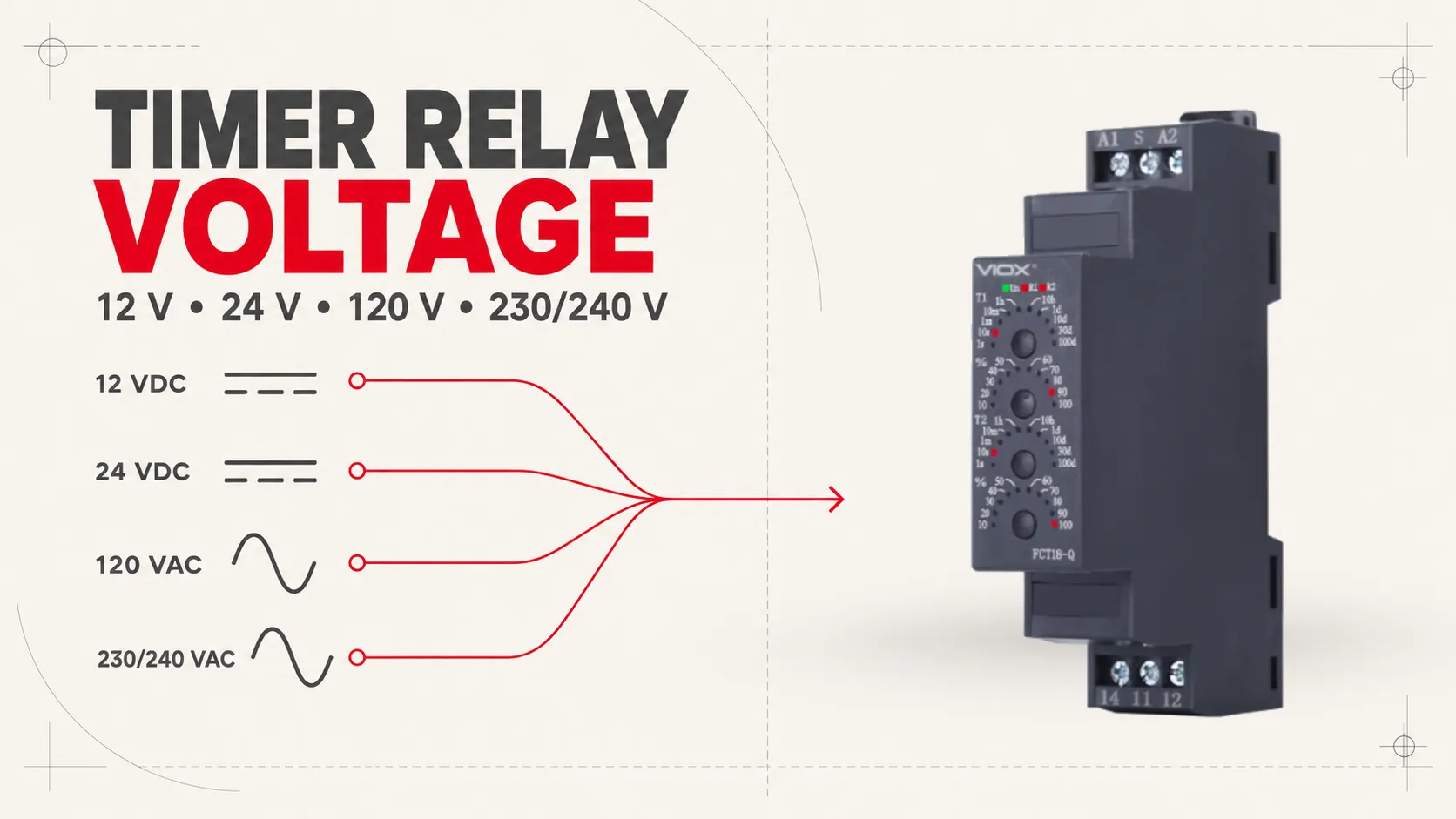
There is no universally best timer-relay voltage. A 24 VDC timer is a natural fit for a panel that already has a 24 VDC control bus and PLC I/O. A 12 VDC version can fit battery-powered equipment. A 120 VAC or 230/240 VAC version can fit an existing line-derived control circuit when the panel design and local rules allow it. A wide-range AC/DC model can reduce part-number variation, but only when its documented input and trigger conditions cover the complete application.
For the wider timing-function and application context, use the complete time delay relay guide. This page resolves one narrower decision: the voltage specification.
Separate the Three Voltage Domains Before Comparing 12V, 24V, 120V, and 240V
A practical way to prevent a voltage-selection error is to identify which circuit each number describes. A timer-relay circuit can contain three different voltage domains:
| Voltage domain | What it does | What to verify |
|---|---|---|
| Supply or operating voltage | Powers the timer’s electronics or coil, commonly through terminals identified as A1/A2 on many DIN-rail devices |
AC or DC, rated range, tolerance, frequency, polarity, consumption, and reset behavior |
| Trigger or control-input voltage | Starts, inhibits, or resets timing on models with a separate input | Input type, reference terminal, logic convention, threshold, pulse duration, and whether it shares the supply potential |
| Output contact or load voltage | Passes through the timer’s output contact to a contactor coil, lamp, valve, controller input, or another load | Contact voltage, current, utilization category/load type, inrush, and required isolation |
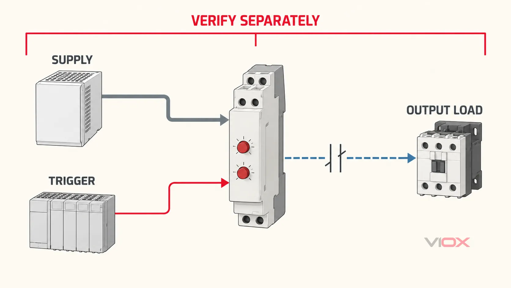
A timer powered by 24 VDC may switch a separate 120 VAC control load if—and only if—the output contact is documented for that load and the circuit is designed with the required isolation and protection. Conversely, a contact marked for 250 VAC does not mean the timer can be powered from 250 VAC.
On an electronic timer, control voltage is sometimes used as a synonym for supply voltage. On other models, “control input” means a separate trigger terminal. Use the manufacturer’s field names and connection diagram rather than assuming the words are interchangeable.
The Six Inputs Required for a Defensible Voltage Selection
Record these conditions before choosing a part number:
- Available control-power source: battery, regulated DC power supply, control transformer, line-derived AC, or another documented source.
- Voltage at the timer: nominal value plus the highest and lowest values that can reach the timer during normal operation, starting events, charging, brownout, or long conductor runs.
- Current type: AC or DC. For AC, record frequency. For DC, record polarity requirements and source grounding arrangement where relevant.
- Start method: timer starts when supply is applied, or remains powered and starts from a separate trigger input.
- System interface: PLC transistor output, dry contact, sensor output, maintained switch, or another controller. The interface must be compatible with the trigger specification, not merely the supply label.
- Target market and documentation: local nominal system, applicable panel rules, required approvals, and the exact product documentation that will accompany the machine.
If any one of these inputs is unknown, the safe procurement answer is not “choose 24 V” or “choose universal.” It is “resolve the missing system condition before ordering.”
Quick Decision Matrix
| Available control system | Timer-relay supply family to evaluate | Good fit when | Reject or investigate when |
|---|---|---|---|
| Nominal 12 VDC | Fixed 12 VDC or a documented wide-range DC/AC-DC input that includes the full source range | The machine already has a 12 V battery or control bus and the timer input remains within its declared range | Battery charging, cranking, conductor drop, or transients can move the timer outside the permitted range |
| Nominal 24 VDC | Fixed 24 VDC or a documented wide-range input | PLC, sensors, and control devices already use the same 24 VDC bus | The timer trigger is incompatible with the PLC output, or the supply can dip below the timer’s reset/operating limit |
| Nominal 24 VAC | Fixed 24 VAC or an explicitly AC/DC-rated input | The existing HVAC or building-control transformer supplies 24 VAC and the timer is rated for the frequency | A “24 V” marking does not state AC/DC, or the trigger input requires a different reference |
| Nominal 120 VAC | Fixed 120 VAC or a documented wide-range AC/AC-DC input | An existing North American control circuit is intentionally line-derived | The device is DC-only, the frequency is not covered, or the panel architecture requires an isolated low-voltage control bus |
| Nominal 230/240 VAC | Fixed input whose declared range covers the actual system, or a documented wide-range AC/AC-DC input | The equipment uses a line-derived control supply and the product documentation covers the installation’s actual voltage | The nameplate says only 230 V or only 240 V without a usable range, frequency, and tolerance for the destination system |
| Multiple markets or uncertain replacement stock | Wide-range input | One documented variant covers every intended AC/DC source and trigger arrangement | “Universal” is inferred from appearance, catalog shorthand, or one headline instead of the exact model datasheet |
How to Choose Each Voltage Family
Choose 12 VDC When the Equipment Is Already a 12 V System
Typical candidates include mobile, vehicle, marine, portable, and battery-backed equipment built around a nominal 12 VDC bus. The advantage is compatibility with the existing source—not an inherent improvement in timer performance.
Do not assume a nominal 12 V battery is a constant 12.0 V source. Verify the timer’s permitted range against the equipment’s documented charging, discharge, starting, and transient conditions. Also check voltage at the timer rather than only at the source. The same absolute conductor drop consumes a larger percentage of a 12 V system than a 24 V system.
For a deeper DC-only comparison, including system-level tradeoffs, see 12 V vs 24 V DC time delay relays.
Choose 24 VDC When It Matches the Control Bus and Interfaces
24 VDC is widely used in industrial control panels, but that does not make it an automatic default. It is the strong choice when the panel already provides a suitably regulated 24 VDC supply and the PLC, sensors, interposing devices, and timer trigger are designed around that bus.
Verify more than the nominal number:
- permitted steady-state input range;
- behavior during power-supply dips and recovery;
- input consumption and available power-supply capacity;
- PNP, NPN, dry-contact, or voltage-trigger compatibility where a separate control input exists;
- polarity and common-reference requirements;
- whether loss and restoration of supply resets, resumes, or restarts timing.
Do not describe every 24 V circuit as Safety Extra-Low Voltage (SELV). That classification depends on the source, separation, earthing, installation, and applicable requirements—not only the nominal voltage printed on the timer.
Choose 24 VAC Only for a Timer That Explicitly Accepts It
24 VAC remains common in some HVAC and building-control systems. A device marked 24 VDC is not automatically compatible with 24 VAC, and a device marked only 24 V is incomplete evidence. Confirm AC acceptance, frequency, permitted range, and the relationship between the supply and any trigger terminal.
Choose 120 VAC for an Existing 120 VAC Control Architecture
A 120 VAC timer can be appropriate in an existing North American panel whose control transformer, contactor coils, wiring method, protection, and maintenance procedures are already built around that voltage.
The reason to choose it is system compatibility. It is not evidence that the timer can switch a larger load, and it does not eliminate the need to check output-contact duty. Because 120 VAC is a hazardous control voltage, panel access, isolation, overcurrent protection, conductor selection, and installation practices must follow the applicable project and jurisdiction requirements.
Choose 230/240 VAC Only After Checking the Actual Input Range
230 V and 240 V are nominal system and equipment labels, not permission to connect any device carrying either number. IEC 60038 provides standardized nominal voltage values used as references for supply systems and equipment design, but the timer decision still comes from its declared operating range.
For a 230/240 VAC application, check:
- the installation’s declared nominal voltage and expected tolerance;
- the timer’s minimum and maximum AC supply voltage;
- rated frequency;
- whether the product is a fixed-voltage or wide-range variant;
- behavior at undervoltage, interruption, and restoration;
- destination-market approvals and panel documentation.
Do not change a 230 V timer to a 240 V timer—or accept the reverse—based on terminology alone. Accept the substitution only when the exact input specification covers the actual supply conditions.
Fixed-Voltage or Wide-Range Input?
A fixed-voltage timer gives a simple match between one control bus and one ordered variant. A wide-range timer can reduce inventory and simplify equipment built for multiple destinations. Neither is automatically superior.
| Selection factor | Fixed-voltage input | Wide-range AC/DC input |
|---|---|---|
| Best use | Stable, known control architecture | Multiple markets, replacement stock, or panels with several approved supply options |
| Verification burden | Confirm one voltage type, nominal value, tolerance, and frequency/polarity | Confirm complete range, AC/DC coverage, frequency, trigger behavior, input consumption, and reset behavior across intended sources |
| Part-number control | More voltage-specific variants | Fewer supply variants, but the suffix must still identify function, contacts, and trigger type |
| Main procurement risk | Ordering the wrong fixed voltage | Treating “universal” as proof that every supply and trigger combination is supported |
As a bounded VIOX example, the FCT18-BP interval timer relay currently lists separate ordering choices for AC 230 V, DC 24 V, and AC/DC 12–240 V supply versions. That product-family example does not mean every VIOX timer uses the same range or suffix. Verify the exact function and model code on the quotation and datasheet.
Five Datasheet Fields That Must Agree
Before approving a timer, place these fields side by side with the project requirement:
| Datasheet field | Acceptance question |
|---|---|
| Rated supply or operating-voltage range | Does the full expected voltage at the timer remain inside the declared range? |
| AC/DC and frequency | Is the input explicitly rated for the source type and AC frequency? |
| Separate trigger/control input | Does its logic, reference, threshold, and minimum pulse behavior match the controller output? |
| Power interruption and reset behavior | Does the timer return to the required safe state after dips, interruptions, or restart? |
| Output-contact rating | Is the contact suitable for the actual load type and switching duty, independently of the supply voltage? |
Timer relays for industrial and residential-associated applications fall within the scope described by IEC 61812-1:2023, which addresses requirements and tests for time relays and coupling relays. A standard reference does not by itself prove that a particular model has been evaluated or certified; obtain model-specific declarations and documentation when compliance evidence is required.
Four Worked Specification Examples
These are illustrative specification patterns, not part-number recommendations.
1. Mobile Machine with a 12 VDC Bus
Known input: nominal 12 V battery system; timer starts when supply is applied; dry-contact output controls an interface relay.
Specification result: timer supply must be DC and cover the machine manufacturer’s documented minimum and maximum voltage at the timer, including the relevant operating states. Output duty is verified separately for the interface relay coil.
2. PLC Panel with a 24 VDC Control Supply
Known input: regulated 24 VDC control bus; PLC transistor output provides the timing command.
Specification result: 24 VDC or a documented wide-range DC-capable timer, with a separate trigger input compatible with the PLC output type and common reference. Supply dip/reset behavior must match the machine’s restart logic.
3. Existing 120 VAC Contactor-Control Panel
Known input: 120 VAC control transformer secondary; timer supply-start function; output drives a contactor coil.
Specification result: 120 VAC or a documented wide-range AC timer with the correct frequency. The output contact must be rated for the coil’s control duty; the timer is not selected from the motor voltage.
4. Equipment Supplied to 230/240 VAC Markets
Known input: line-derived control supply with destination-dependent nominal voltage; the same machine design is intended for more than one market.
Specification result: a fixed or wide-range AC input whose declared limits cover every approved destination supply and frequency, supported by the appropriate product and panel documentation. The phrase 230/240 V compatible should not appear on the RFQ unless the actual range has been verified.
Convert the Decision into an RFQ Line
Use a procurement statement that can be checked without interpreting marketing language:
Timer relay supply: [nominal voltage] [AC/DC], permitted input range [minimum–maximum], [frequency or polarity], [supply-start/separate-trigger], trigger type [if applicable], reset behavior [required state], output [contact arrangement and actual load duty], destination market [country/standard evidence required].
Example:
Timer relay supply: 24 VDC from the panel control supply; permitted input range must cover the documented bus tolerance; separate PNP trigger referenced to the control 0 V; timing resets on loss of control supply; one timed changeover output suitable for the declared contactor-coil duty; provide model-specific datasheet and required destination-market compliance documents.
This wording prevents three common procurement failures: choosing from the load voltage, ordering the wrong AC/DC variant, and accepting a wide-range headline without the required trigger and reset behavior.
After the voltage requirement is fixed, use the complete timer-relay selection guide to specify timing function, range, output arrangement, contact duty, mounting, and environment. When the complete requirement is known, compare the VIOX DIN-rail timer relay range or send the RFQ fields to [email protected].
Source References
- International Electrotechnical Commission, IEC 61812-1:2023 — Time relays and coupling relays for industrial and residential use: official scope and edition information.
- International Electrotechnical Commission, IEC 60038:2009+A1:2021 — IEC standard voltages: standardized nominal voltage values for supply systems and equipment design.
- VIOX Electric, FCT18-BP Interval Timer Relay: first-party model coding and supply-voltage variants used in the bounded product example.