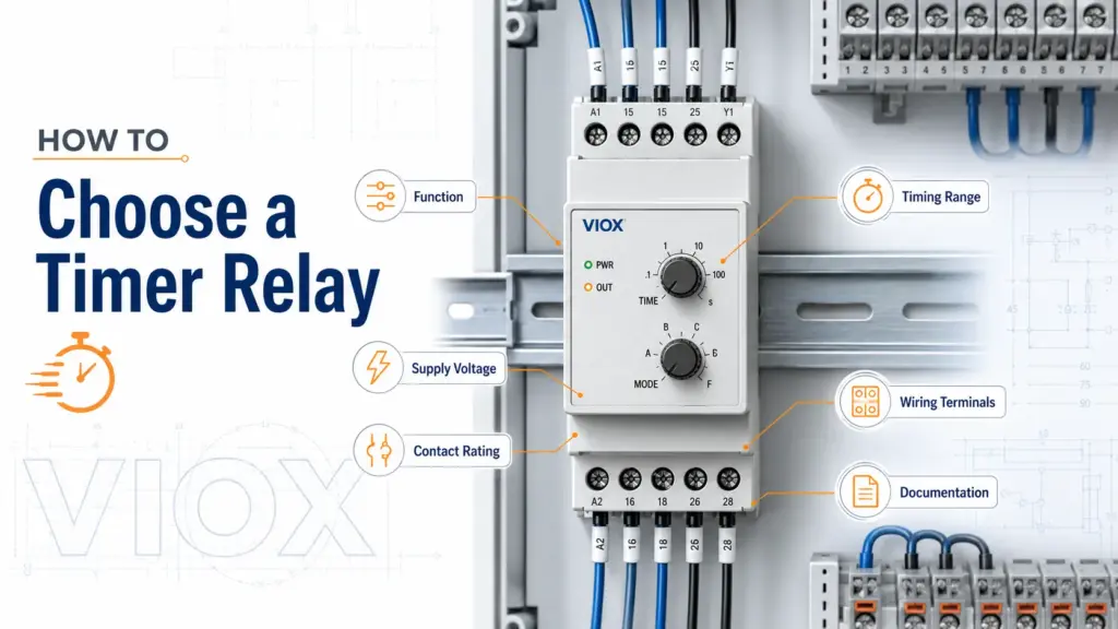
Quick Answer: How Do You Choose a Timer Relay?
Choose a timer relay by matching seven practical requirements: timing function, supply voltage, contact rating, timing range, output contact arrangement, mounting format, and wiring terminals. The biggest mistake is choosing by delay time alone while ignoring load type, control voltage, and contact rating.
Use this sequence:
- Choose the timer function: on-delay, off-delay, interval, cyclic, star-delta, or multifunction.
- Match the supply voltage to the control circuit.
- Check contact rating against the real load type, not only the headline ampere number.
- Select a timing range that gives enough adjustment without poor setting resolution.
- Choose the output contact arrangement: SPDT, DPDT, NO/NC, or multiple contacts.
- Confirm mounting and wiring terminals fit the panel design.
- Verify documentation, standards, and supplier support before approval.
If you need the basic device definition first, see What Is a Time Relay?. If you are already comparing products, visit the VIOX Timer Relay product page.
Timer Relay Selection Checklist
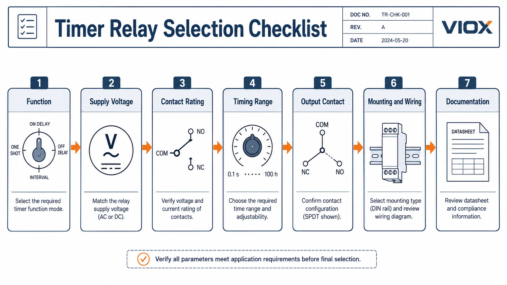
| Selection factor | What to check | Common mistake |
|---|---|---|
| Function | On-delay, off-delay, interval, cyclic, star-delta, multifunction | Buying a single-function relay when multiple modes are needed |
| Supply voltage | 12 V, 24 V, 110 V, 230 V, AC/DC, or universal input | Matching load voltage instead of control voltage |
| Contact rating | AC-1, AC-15, DC-13, resistive vs inductive load | Using resistive current rating for contactor coils or solenoids |
| Timing range | Seconds, minutes, hours, adjustable range, setting resolution | Choosing too wide a range and losing setting precision |
| Output contact | SPDT, DPDT, NO/NC, number of outputs | Not enough contacts for interlock or signal feedback |
| Mounting | DIN rail, socket, panel mount, plug-in base | Selecting a relay that does not fit the control cabinet |
| Wiring terminals | A1/A2, 15/16/18, trigger input, reset input | Miswiring supply, trigger, and output contact terminals |
| Documentation | Datasheet, wiring diagram, timing chart, standards | Selecting from a catalog image instead of the actual model data |
Step 1: Choose the Timer Function

Function is the first decision. A timer relay is not just “a relay with seconds on the dial.” The selected timing mode must match what the circuit is supposed to do.
| Timer relay function | How it behaves | Typical use |
|---|---|---|
| On-delay | Output changes after input/supply is applied and delay expires | Delayed motor start, sequential startup, alarm delay |
| Off-delay | Output remains active for a set time after trigger or supply condition changes | Fan run-on, pump delay, ventilation purge |
| Interval | Output turns on for a fixed time after trigger | Timed pulse, alarm output, short actuator signal |
| Cyclic / repeat cycle | Output alternates ON/OFF repeatedly | Flashing signal, periodic pump or lubrication cycle |
| Star-delta timer | Controls transition from star to delta in a motor starter | Reduced-voltage motor starting |
| Multifunction timer | Several selectable timing modes in one device | OEM panels, spare-parts reduction, flexible commissioning |
If the panel only needs one fixed function and misconfiguration risk must be low, a single-function timer relay may be the better choice. If the panel builder wants one SKU across many variants, a multifunction timer relay may be more practical. For that decision, see Multifunction Timer Relay vs Single-Function Timer Relay.
Step 2: Match the Supply Voltage
Supply voltage is the voltage that powers the timer relay electronics or coil. It is not automatically the same as the voltage being switched by the output contact.
Common timer relay supply categories include:
- 12 VDC
- 24 VAC/DC
- 110-120 VAC
- 220-240 VAC
- wide-range or universal AC/DC input
A common wiring error is selecting a relay because the load is 230 VAC, even though the panel control circuit is 24 VDC. The timer relay supply must match the control circuit connected to its supply terminals.
Example: a 24 VDC timer relay may use A1/A2 for 24 VDC supply while its output contact switches a separate AC control circuit, provided the output contact is rated for that load.
For deeper voltage selection, see Timer Relay Voltage Selection Guide: 12V, 24V, 120V, 230V.
Step 3: Check Contact Rating and Load Type
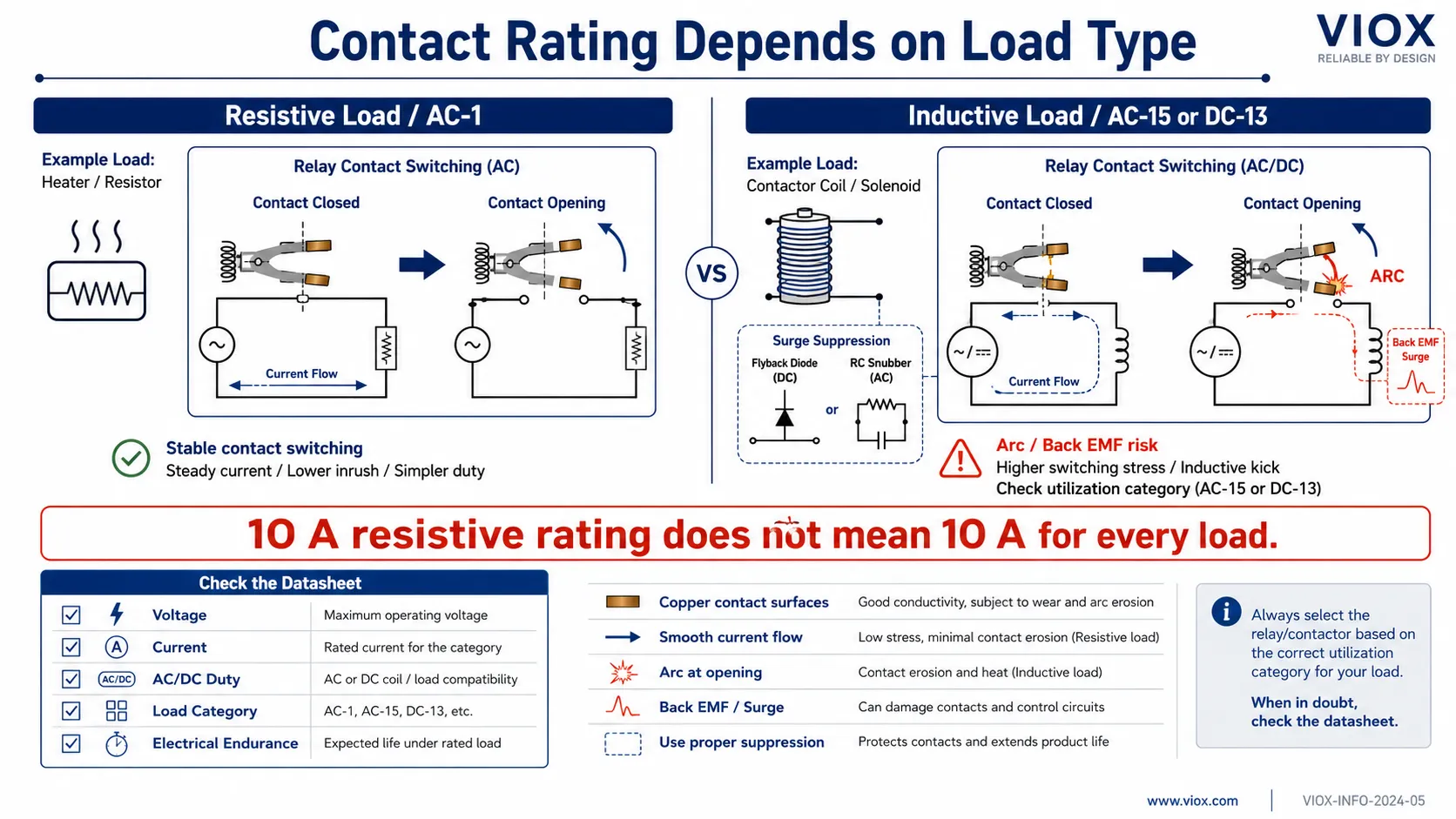
Contact rating is where many timer relay failures start.
The output contact does the actual switching. A timer relay may time correctly but still fail early if its contact is not suitable for the load.
Check:
- rated voltage of the contact
- rated current of the contact
- AC or DC switching duty
- resistive or inductive load
- utilization category such as AC-1, AC-15, or DC-13 where applicable
- contact arrangement such as SPDT or DPDT
- mechanical and electrical endurance data in the datasheet
Do not use the resistive-load ampere rating as if it applies to every load. A contact rated for a high current on a resistive load may have a much lower rating when switching an inductive control load such as a contactor coil, solenoid, valve, or small motor auxiliary circuit.
For example, a relay contact listed around 10 A at 250 VAC for resistive duty may be rated for only a few amps under an inductive control-duty category such as AC-15. The exact value must come from the datasheet, but the rule is simple: select by load category, not by the largest ampere number printed on the relay.
If contact failure on inductive loads is your main concern, read Why Time Relay Contacts Fail on Inductive Loads: AC-1 vs AC-15 Ratings.
Step 4: Select the Timing Range and Setting Precision
The timer relay should cover the required delay, but not with an unnecessarily wide range.
If the application needs a 3-second delay, a relay with a 0.1-10 second range is usually easier to set accurately than a relay with a 0.1 second to 100 hour range. Very wide ranges can be useful, but they can also reduce practical setting resolution on analog dials.
Check:
- minimum and maximum time range
- scale readability
- setting method: dial, DIP switch, rotary selector, or digital display
- repeat accuracy and tolerance
- reset behavior
- how the relay behaves after power loss
For timing calculations and range decisions, see How to Calculate Timer Relay Time Range.
Step 5: Choose Mounting Type and Wiring Terminals
Timer relays are common in control panels, motor starter panels, HVAC cabinets, pump panels, and machine control boxes. The mounting format must fit the panel design.
Common mounting types include:
- DIN rail timer relay
- plug-in timer relay with socket
- panel-mount timer
- PCB or embedded timing module
For industrial panels, DIN rail and plug-in socket types are the most common. DIN rail mounting is compact and fast for panel builders. Plug-in socket types can be useful where fast replacement matters.
Common terminal markings
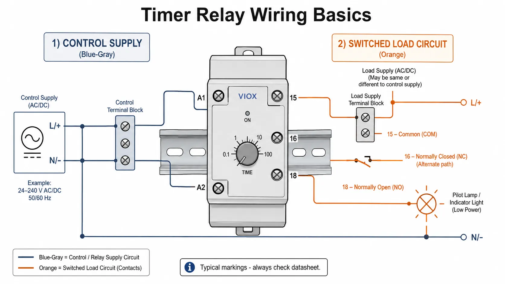
Many timer relays use terminal conventions such as:
| Terminal | Common meaning |
|---|---|
| A1 / A2 | Supply or control power terminals |
| 15 | Common contact terminal |
| 16 | Normally closed contact |
| 18 | Normally open contact |
| B1 / S / Trigger | External trigger or control input, depending on model |
| Reset | Reset input, depending on function |
These markings are common but not universal. The printed wiring diagram on the relay body or datasheet is always the final authority.
For wiring details, use Time Delay Relay Wiring Diagram Guide.
Step 6: Match the Application
Motor starter panels
Timer relays are used for delayed start, auxiliary motor sequencing, anti-restart delay, and star-delta transition. The timer relay usually switches a contactor coil or control circuit, not the motor power circuit directly.
If the timer relay is used with a motor starter, check contactor coil voltage, contact rating for AC-15 duty, wiring terminal logic, and reset behavior.
Pump and compressor control
Pumps and compressors often need delay logic to prevent short cycling, control run-on, or sequence multiple loads. The key selection points are off-delay/on-delay function, timing range, restart behavior after power loss, and enclosure environment.
For pump protection context, see Prevent Pump Short Cycling Time Delay Relay Guide.
HVAC and fan control
HVAC circuits may use timer relays for compressor delay, fan run-on, purge timing, damper delay, and staged startup. The selected relay must match the control voltage and should not be chosen only by delay range.
For compressor-specific timing, see HVAC Time Delay Relay Compressor Protection.
Lighting and signal circuits
Timer relays can provide delayed lighting, flashing, staircase timing, signal delay, or warning output. If the task is based on daily/weekly scheduling rather than control-sequence timing, a timer switch may be a better device.
Simple machine automation
For a single local timing function, a timer relay can be cleaner than writing PLC logic. For multi-input machine sequencing, interlocks, alarms, data logging, or HMI-adjustable timing, PLC logic is usually better.
For that architecture decision, see Timer Relay vs PLC Timer.
Step 7: Check Standards, Documentation, and Supplier Support
Timer relays are commonly associated with the IEC 61812 standard family for time relays. In a real project, the required documentation depends on the target market, panel standard, and customer specification.
Before approval, check:
- product datasheet
- wiring diagram
- timing chart
- supply voltage range
- output contact ratings by load type
- terminal marking
- mounting dimensions
- environmental limits
- applicable certification or compliance documents for the exact model
- availability of replacement or equivalent models
Do not assume one relay is suitable because a different product in the same catalog family has a certification mark. Match the exact model number and rating.
For datasheet interpretation, see How to Read Time Delay Relay Datasheets & Specifications. For compliance background, see IEC 61812-1 Time Delay Relay Compliance Guide.
How to Evaluate a Timer Relay Supplier
Instead of choosing a timer relay by brand list or price range, evaluate the supplier by engineering support and documentation quality.
Use this checklist:
| Supplier check | Why it matters |
|---|---|
| Clear function table | Prevents wrong mode selection |
| Accurate wiring diagrams | Reduces commissioning errors |
| Contact ratings by load type | Prevents contact welding or early failure |
| Voltage options | Helps match global panel designs |
| DIN rail and socket options | Supports different cabinet layouts |
| Stable model availability | Reduces future replacement problems |
| Technical support | Helps panel builders and OEMs select correctly |
| Packaging/OEM support | Useful for distributors and private-label projects |
For manufacturer-level evaluation, see Timer Relay Manufacturer and Time Relay Manufacturer Selection Guide.
Common Timer Relay Selection Mistakes
Mistake 1: Choosing by delay time only
The timing range may be correct, but the supply voltage, function mode, contact rating, or terminal logic may be wrong.
Mistake 2: Confusing supply voltage with contact voltage
A timer relay powered by 24 VDC may have contacts rated for a different circuit. The supply terminals and output contacts are separate specifications.
Mistake 3: Ignoring inductive load rating
Contactor coils, solenoids, valves, and small motors stress relay contacts differently from resistive loads. Check AC-15 or DC-13 data where applicable.
Mistake 4: Selecting multifunction when simplicity matters
Multifunction relays are flexible, but wrong mode or range settings can cause commissioning errors. For fixed repetitive applications, single-function may be cleaner.
Mistake 5: Choosing too wide a timing range
A wide range sounds useful, but it can make precise setting harder on analog dials.
Mistake 6: Miswiring A1/A2 and output contacts
The relay supply terminals power the timer. The output contacts switch a separate circuit. Mixing these up is a common field error.
Mistake 7: Using a standard timer relay for a safety function
An ordinary timer relay is not automatically a safety timer. If timing is part of a safety-related control function, use devices and architecture designed and certified for that safety role.
FAQ
What is the first thing to check when choosing a timer relay?
Start with the function. Decide whether the circuit needs on-delay, off-delay, interval, cyclic, star-delta, or multifunction timing. After that, check supply voltage, contact rating, timing range, mounting, and wiring.
How do I choose timer relay voltage?
Choose the relay supply voltage to match the control circuit connected to the relay supply terminals, commonly A1/A2. Do not choose supply voltage based only on the load voltage being switched by the output contact.
Can a timer relay switch a motor directly?
Usually no. In most motor-control panels, the timer relay switches a contactor coil or control circuit, and the contactor switches the motor power. Direct motor switching requires a contact rating explicitly suitable for that load.
What contact rating should I check?
Check voltage, current, AC/DC duty, and load category. For inductive control loads, look for ratings such as AC-15 or DC-13 where applicable, not only the resistive-load amp rating.
Is a multifunction timer relay better?
It is better when the panel needs flexibility, standardization, or future function changes. It is not always better for fixed repetitive applications where wrong settings create more risk than benefit.
What do A1 and A2 mean on a timer relay?
A1 and A2 commonly identify the timer relay supply terminals. The exact voltage, AC/DC compatibility, and polarity requirements must be checked on the relay marking or datasheet.
What do 15, 16, and 18 mean on a timer relay?
On many industrial relays, 15 is common, 16 is normally closed, and 18 is normally open. This is common but not universal, so always check the wiring diagram.
What is the difference between a timer relay and a PLC timer?
A timer relay is a standalone physical timing device. A PLC timer is software logic inside a programmable controller. Use a timer relay for simple fixed local timing; use PLC timing for complex sequences, diagnostics, communication, and HMI-adjustable logic.
Which standard applies to timer relays?
The IEC 61812 standard family is commonly referenced for time relays. Actual compliance depends on the exact product model, documentation, target market, and project requirement.
Summary
The right timer relay is selected by function first, then by electrical and mechanical fit. A good selection checks timing mode, supply voltage, contact rating, timing range, output contact arrangement, mounting, wiring terminals, and documentation.
For VIOX timer relay selection, start from the Timer Relay product page, then use the supporting guides for wiring diagrams, voltage selection, datasheet reading, and inductive load contact ratings.
