On this page
A time delay relay changes a control output according to two conditions: an input event and a time rule. Depending on the selected function, it can delay a start, delay a stop, create a fixed-duration pulse, repeat an ON/OFF cycle, or coordinate a star-delta transition.
The most reliable way to choose one is to define the required output timeline first. Then verify the trigger method, reset and power-loss behavior, supply voltage, output contact duty, and mounting against the exact model datasheet. Two timer relays with similar dials or terminal counts can still perform different sequences.
| Required control result | Likely timer function | Critical point to verify |
|---|---|---|
| Wait before turning the output ON | On-delay | What starts timing and what resets it |
| Keep the output ON after a command ends | Off-delay | Whether control power remains available during timing |
| Turn the output ON for one defined period | Interval or one-shot | Power-triggered versus signal-triggered operation |
| Alternate ON and OFF repeatedly | Repeat-cycle | ON-first/OFF-first behavior and whether the two times are independent |
| Transfer a motor starter from star to delta | Star-delta | Dedicated changeover sequence and interlocking requirements |
| Use one device for several possible sequences | Multifunction | Available modes, selector settings, and commissioning control |
This page is the orientation hub for timer relay functions and applications. For a narrower terminology explanation, start with What Is a Time Relay?.
How a Time Delay Relay Works
At orientation level, every timer relay can be understood as four blocks:
Supply or trigger condition
            ↓
      Timing function
            ↓
   Output changes state
            ↓
 Reset condition restores or restarts the sequence
The input may be the application of control power, a separate trigger signal, or the removal of a signal. The timing circuit evaluates that event against the selected function and preset time. The output then changes a relay contact or, on some designs, an electronic output. The reset condition determines what happens when the signal changes again or power is interrupted.
That last point is easy to miss. “Five-second timer” does not describe a complete device. A useful functional specification must say what happens before, during, and after those five seconds, and what cancels or restarts the sequence.
The operating-mode descriptions below are practical categories, not a universal naming code. Manufacturers can use different mode letters and names, so the timing diagram in the exact datasheet remains authoritative.
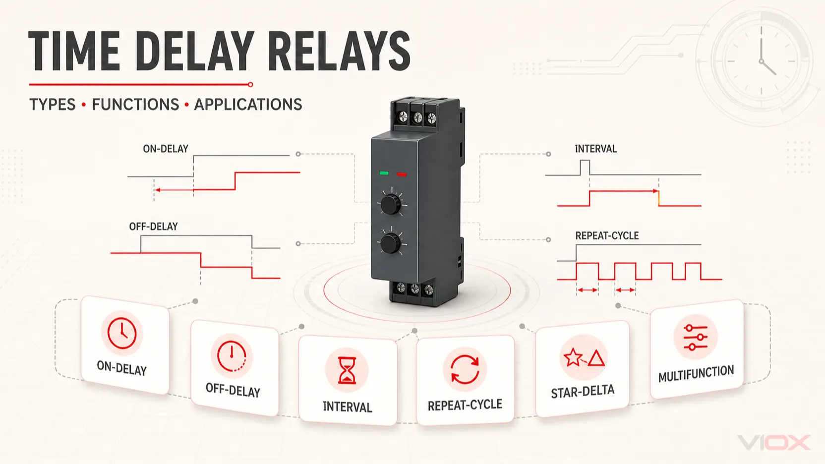
Six Practical Types of Time Delay Relays
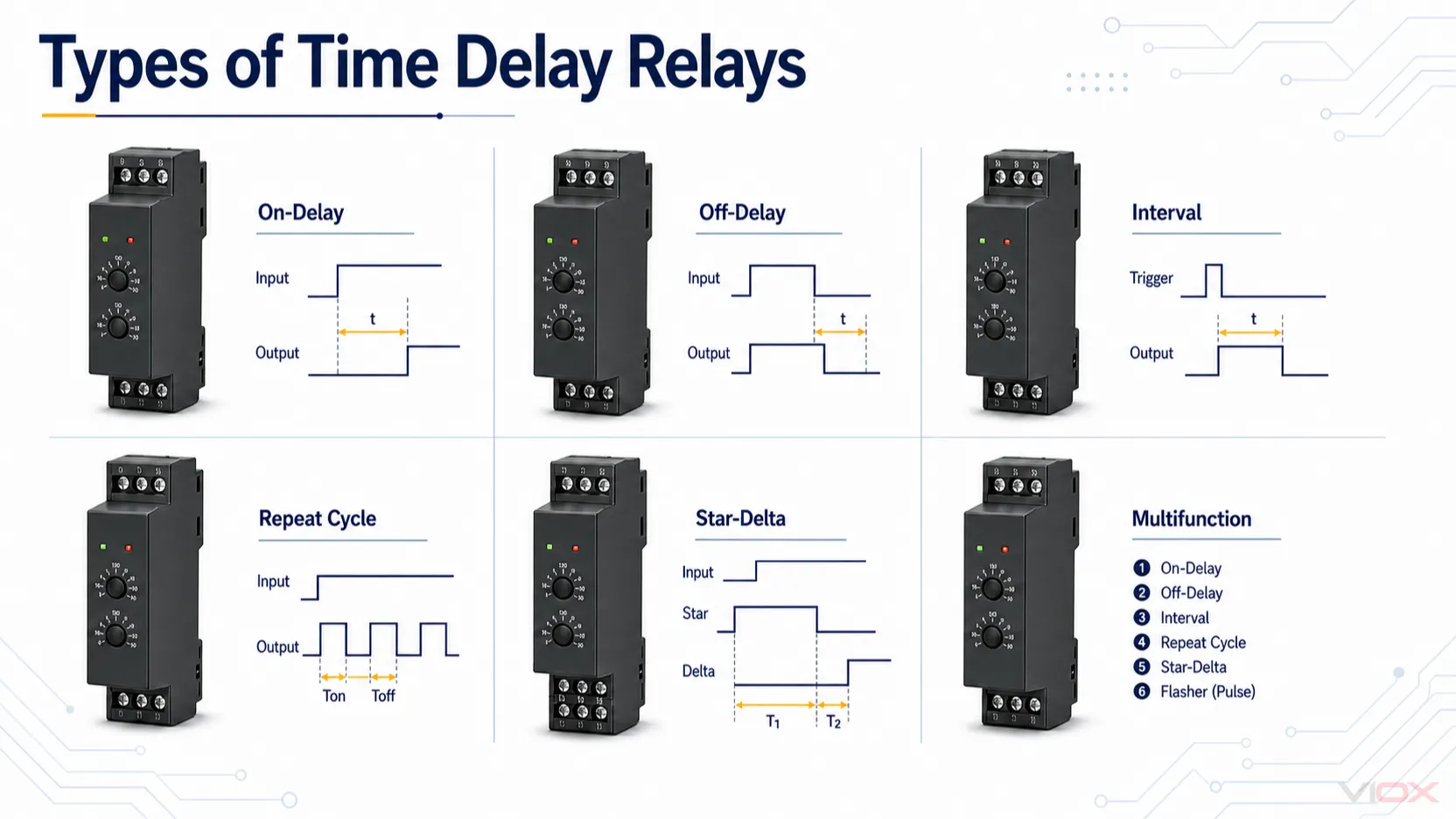
The diagrams compare timing behavior conceptually. Terminal markings and product details shown in the graphic are not universal wiring instructions.
The six categories below cover the most common selection conversations. They are not mutually exclusive product constructions: a multifunction relay may contain several of the operating functions listed beside it.
| Practical category | Timing begins when | Output during timing | Output after timing | Main selection risk |
|---|---|---|---|---|
| On-delay | Supply or qualifying trigger turns ON | Remains in its initial state | Changes state | Input may not remain valid long enough to complete timing |
| Off-delay | Qualifying trigger turns OFF | Remains in its operated state | Returns to its initial state | Confusing signal off-delay with operation after total power loss |
| Interval | Supply or trigger initiates the cycle | Operates for the preset interval | Returns to its initial state | Choosing the wrong trigger or retrigger behavior |
| Repeat-cycle | Supply or trigger initiates cycling | Alternates ON and OFF | Continues until its stop/reset condition | Assuming every model starts in the same state |
| Star-delta | Motor-start command initiates the sequence | Star stage is maintained | Star releases and delta is permitted | Using a general timer without the required transition logic |
| Multifunction | Depends on the selected mode | Depends on the selected mode | Depends on the selected mode | Incorrect mode, time range, or setting during commissioning |
On-Delay Timer Relay
An on-delay relay delays output operation after its initiating condition becomes true. A common power-triggered sequence is:
Input ON → timing starts → preset time expires → output operates
Input OFF → output returns and timer resets
Use on-delay when equipment must wait before starting—for example, to stagger contactor commands, prevent an immediate compressor restart, or establish a startup order. If the initiating signal disappears before time expires, many on-delay modes reset without operating the output; signal-memory and pulse-triggered exceptions must be checked in the datasheet.
Off-Delay Timer Relay
An off-delay function is used when the output should remain operated after a command signal ends. In a common signal-triggered design:
Trigger ON → output operates
Trigger OFF → timing starts → preset time expires → output returns
Typical uses include fan post-run, purge time, delayed lighting turn-off, and holding an auxiliary control signal during shutdown. A standard off-delay mode often needs its timer supply to remain available while the trigger input changes. This is different from maintaining an output after the timer itself loses power.
For a focused timing comparison, see On-Delay vs Off-Delay Timer.
Interval and One-Shot Timer Relay
An interval function operates the output for a defined period and then returns it automatically:
Trigger → output operates and timing starts → preset time expires → output returnsThis behavior fits a dosing pulse, alarm pulse, signal extension, or other fixed-duration action. “Interval” and “one-shot” are sometimes used for closely related modes, but they are not guaranteed to have the same trigger, reset, or retrigger behavior. Check whether the cycle begins at power-up or from a separate signal, whether a new trigger restarts timing, and whether the input must be removed before another cycle can begin.
Repeat-Cycle Timer Relay
A repeat-cycle timer alternates its output between ON and OFF states:
ON for T1 → OFF for T2 → repeat until stop or resetIt is commonly used for flashing signals, periodic ventilation, lubrication cycles, and simple intermittent operation. Before selecting one, verify whether the first period is ON or OFF, whether T1 and T2 are independently adjustable, and what the relay does after a supply interruption.
Star-Delta Timer Relay
A star-delta timer is a specialized motor-control timer. It coordinates the transition from the star starting stage to the delta running stage in a starter designed for that method.
| Stage | Required control result | Timer responsibility |
|---|---|---|
| Start | Main and star paths are commanded according to the starter design | Begin the star period |
| Transition | Star must release before delta is enabled | Provide the defined changeover sequence |
| Run | Delta path remains enabled with the main path | Hold the final control state |
| Stop or trip | Starter contactors release | Reset for the next start |
The correct star period and transition behavior depend on the motor, contactors, mechanical load, and complete starter design. A general on-delay timer is not automatically an acceptable substitute for a dedicated star-delta function, and this overview is not a starter wiring instruction.
Multifunction Timer Relay
A multifunction timer relay combines several selectable modes in one device. It can be useful for flexible OEM panels, distributor stock, maintenance spares, and projects whose timing logic may change.
Flexibility also creates a commissioning risk. A compatible supply and terminal layout do not compensate for a wrong mode selection. Record the function, time range, dial or digital setting, trigger behavior, and reset behavior in the panel documentation. For fixed, high-volume equipment, a single-function model may reduce setting errors; see Multifunction vs Single-Function Timer Relays for the full decision.
Off-Delay vs True Power-Off Delay
This distinction deserves a separate checkpoint because the two requirements sound similar but have different energy conditions.
| Requirement | Timer supply while delay runs | What must be verified |
|---|---|---|
| Signal off-delay | Usually remains available | Trigger input, output state, and reset sequence |
| True power-off delay | Main supply is removed | Whether the exact device can maintain its output, for how long, and under what load conditions |
In a conventional electronic off-delay arrangement, the timing electronics and output mechanism still need energy while counting down. If the timer loses all supply and has no specified stored-energy or latching arrangement, it cannot be assumed to continue timing.
Therefore, do not select a “power-off delay” application by the words off delay alone. Use the exact timing diagram and product documentation, especially for purge, brake, alarm-hold, or controlled-shutdown circuits.
Other Ways Timer Relays Are Classified
Function describes the required signal sequence. Procurement also requires a separate classification of how the device is adjusted, mounted, and connected to the control system.
| Classification layer | Common options | Why it matters |
|---|---|---|
| Function coverage | Single-function, multifunction | Controls flexibility and setting-error risk |
| Timing implementation and interface | Electromechanical or pneumatic legacy designs; analog electronic; digital electronic | Affects adjustment method, replacement fit, available modes, and documentation |
| Mounting | DIN rail, plug-in socket, panel mount, printed circuit board | Affects panel space, wiring, replacement, and operator access |
| Output interface | Relay contact, transistor output on supported models | Determines how the timer interfaces with a contactor coil, programmable logic controller input, or other control load |
| Trigger arrangement | Supply-triggered, separate signal-triggered, model-specific inputs | Determines what starts and resets timing |
Do not infer accuracy, time range, contact capacity, environmental limits, or certification from the technology or mounting label. Those are exact-model specifications. The time delay relay datasheet guide explains how to verify them.
Time Delay Relay Applications by Control Requirement
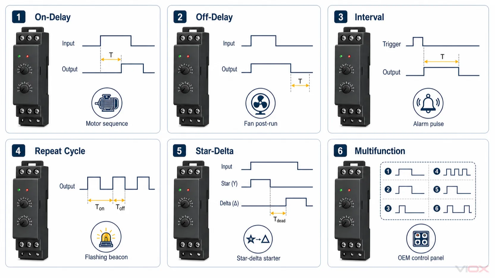
Use the graphic to compare functional sequences, not to identify universal terminals. Always follow the exact relay timing and wiring diagram.
Application names alone do not select a relay. The useful question is: what must the output do when the control condition changes?
| Application requirement | Likely function | Next verification |
|---|---|---|
| Start several motors or conveyors in sequence | On-delay | Required sequence, reset behavior, and contactor-coil duty |
| Prevent immediate compressor restart | On-delay or a dedicated anti-short-cycle control | What event starts the lockout and whether every restart path is covered |
| Keep a fan operating after a stop command | Off-delay | Whether timer control power remains available |
| Operate a pump or valve for one fixed period | Interval | Trigger source and retrigger behavior |
| Flash a beacon or cycle ventilation | Repeat-cycle | ON-first/OFF-first and separate T1/T2 adjustment |
| Transfer a suitable motor starter from star to delta | Star-delta | Complete starter sequence and interlocks |
| Standardize a flexible OEM control platform | Multifunction | Mode governance, documentation, and replacement controls |
For application-specific design, use the corresponding deep guide rather than treating this table as a final specification. Examples include HVAC compressor timing and pump short-cycle prevention.
How to Select the Right Timer Function
Use these five questions as a first pass:
- What exact output timeline is required? Draw the input and output states before choosing a product name.
- What starts and resets timing? Distinguish application/removal of supply from a separate trigger signal.
- What happens during a power interruption? Specify immediate reset, retained state, restart, or verified power-off-delay behavior.
- What will the output switch? Identify the control load and its duty; a resistive current headline is not enough for an inductive contactor coil or solenoid.
- What physical and documentation constraints apply? Verify supply, range, mounting, terminals, environment, approvals, and the exact timing diagram.
These questions identify a likely device family, not a purchase-ready part number. Use the timer relay selection guide to convert the application into a complete specification. For model comparison, review the published VIOX timer relay range.
Basic Wiring Boundary
A timer relay normally belongs in the control circuit:
Control supply or trigger
            ↓
        Timer relay
            ↓
   Timed output interface
            ↓
Contactor coil, PLC input, alarm, or other compatible control load
The timer provides timing logic; it is not automatically the device that switches motor power. Terminal designations vary between manufacturers and models, and even familiar markings can serve different functions in different operating modes.
For terminal-level diagrams, use the Time Delay Relay Wiring Guide. For a motor starter, use the dedicated time relay motor-starter wiring guide. Work on de-energized equipment unless an authorized test procedure specifically requires energized measurements, and follow the applicable site and electrical-safety rules.
Setting and Commissioning Checkpoint
Before energizing the controlled equipment:
- Match the selected function to the intended input/output timing sketch.
- Confirm the time range before setting the fine adjustment.
- Verify supply and trigger terminals from the exact model diagram.
- Confirm the intended normally open or normally closed output path.
- Check output duty for the connected control load and use appropriate suppression where required by the component documentation.
- Test the sequence under controlled conditions, including reset and power-interruption behavior.
- Record the mode, range, final setting, and model reference in the panel documentation.
If a bench test is required, follow the step-by-step time delay relay test guide rather than improvising inside an energized panel.
Quick Troubleshooting Triage
| Symptom | First checks | Deeper resource |
|---|---|---|
| No indication or timing activity | Correct supply, protective device, terminal identification | Time delay relay not working |
| Timing starts but the output never changes | Function selection, qualifying trigger, output terminal, reset condition | How to test a time delay relay |
| Delay or reset is inconsistent | Supply stability, selected range, trigger duration, reset time | Time delay relay not working |
| Relay operates but the load does not | Load circuit, contact path, coil voltage, contact duty | Relay clicks but load does not operate |
| Contacts overheat, weld, or fail early | Inductive duty, switching frequency, suppression, interface choice | Why timer contacts fail on inductive loads |
The timing diagram is usually more useful than the product name when diagnosing a sequence problem. It shows the required relationship between input, time, output, and reset.
Standards and Rating Boundary
IEC 61812-1:2023 covers requirements and tests for time relays and coupling relays within its stated industrial and residential-use scope. A standard’s scope does not prove that every timer relay is certified, that a complete control panel complies, or that a component is suitable for a particular installation.
For that distinction, see the IEC 61812-1 time relay compliance guide. Always request model-specific declarations, ratings, diagrams, and certificates when they are required for a project or market.
Frequently Asked Questions
What are the main types of time delay relays?
The most common practical categories are on-delay, off-delay, interval or one-shot, repeat-cycle, star-delta, and multifunction timer relays. Power-off delay is another important behavior that must be distinguished from ordinary signal off-delay operation.
What is the difference between on-delay and off-delay?
On-delay waits before operating the output after the initiating condition appears. Off-delay operates the output first and waits before returning it after the qualifying trigger is removed. The exact supply, trigger, and reset arrangement is model-specific.
Can an off-delay timer keep working after all power is removed?
Not automatically. Many off-delay modes require timer power to remain available while a separate trigger changes state. If the output must remain active after total supply loss, select a device with explicitly documented power-off-delay behavior.
Is a multifunction timer always better than a single-function timer?
No. Multifunction timers reduce part-number variety and offer flexibility. Single-function timers can simplify commissioning and reduce accidental mode changes in fixed equipment. The better choice depends on the application and configuration-control process.
Can a timer relay switch a motor directly?
A timer relay is normally used in the control circuit to command a correctly rated contactor or motor starter. Whether any output can switch a particular load depends on the exact output rating, utilization duty, load characteristics, and manufacturer instructions.
Are terminal numbers the same on every time delay relay?
No. Some numbering conventions are common, but terminal functions, trigger inputs, second contact sets, and timing modes vary. Use the wiring and timing diagram for the exact manufacturer and model.
Sources
- IEC 61812-1:2023 — Time relays and coupling relays: requirements and tests
- Schneider Electric — 9050JCK timer function descriptions
- Schneider Electric — on-delay timer operation
- Schneider Electric — off-delay timer operation
- Omron H3DS solid-state timer specifications and operating modes
Evaluate a VIOX Timer Relay for Your Control Sequence
Once the required timing function is defined, compare the published VIOX timer relay series by operating mode, supply, time range, trigger arrangement, output duty, and mounting. For OEM or panel-building support, send the timing sketch and application requirements to [email protected].