On this page
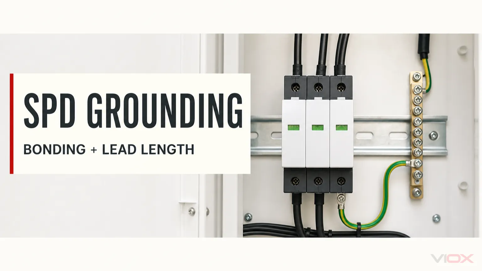
A panel-mounted surge protective device (SPD) depends on a correctly bonded electrical system and a short, low-impedance connection to the manufacturer-specified protective earth (PE) or equipment-grounding point. The normal remedy is not to bypass the panel’s grounding bar and run an isolated conductor to a separate ground rod. An unbonded electrode, an unauthorized neutral-to-ground connection, or an excessively long SPD connection can create electrical hazards and reduce protection.
When a surge protector appears ineffective, investigate the complete protection path: system grounding, equipotential bonding, connection length, protection modes, device condition, and coordination. A green status window alone cannot verify all six.
Key Takeaways
- Connect the SPD to the approved PE/equipment-grounding terminal, bonded grounding bar, or other bonding point explicitly permitted by the product instructions and applicable code.
- Never connect an SPD to a separate, isolated ground rod that is not integrated with the building’s grounding electrode and bonding system.
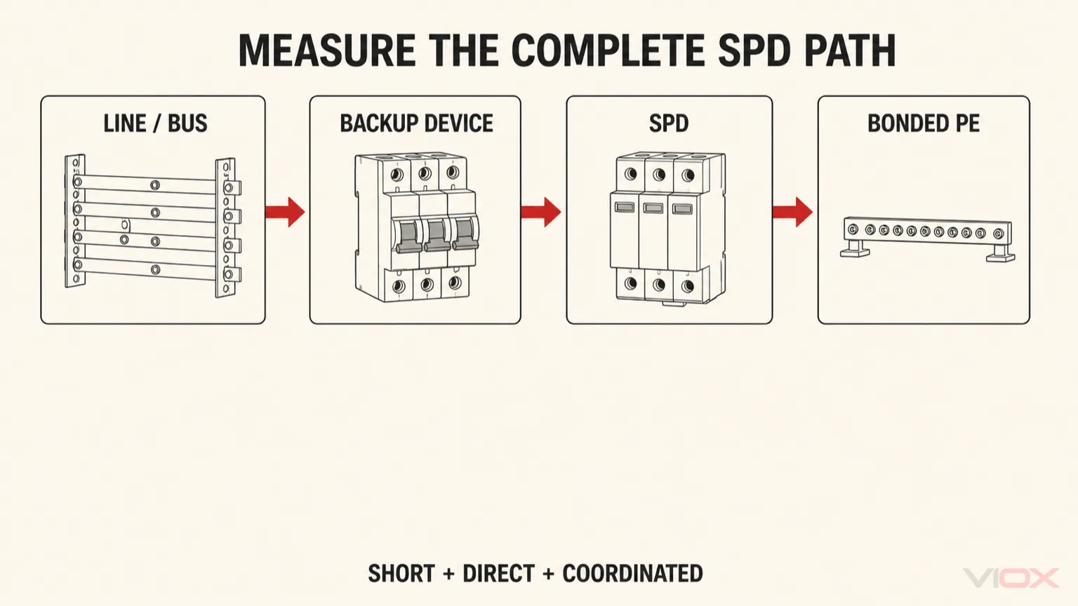
- Shorten the entire SPD connection path, including line, any required disconnect or backup device, and PE—not simply the distance from the panel to soil.
- Keep neutral and equipment grounding separate in subpanels where the applicable system and installation rules require separation.
- Soil resistance, continuity, fault-current performance, and high-frequency surge impedance are different measurements; no single earth-resistance number proves an SPD installation is effective.
- Opening energized equipment, changing bonding conductors, adding electrodes, or correcting service and subpanel connections requires a qualified electrician.
What a Panel Surge Protector Actually Does
An SPD limits transient voltage between the conductors connected to its declared protection modes. Depending on its design and the electrical system, those modes may include line-to-neutral, line-to-PE, neutral-to-PE, or line-to-line.
During a surge, the device provides a temporary controlled current path and limits the voltage difference appearing across the protected conductors. It does not absorb every lightning event, permanently prevent all overvoltage, or send every surge directly into soil through one dedicated wire.
The useful engineering objective is equipotential bonding: keeping relevant conductors, equipment frames, and protected interfaces at a sufficiently similar potential during the transient. The grounding electrode system contributes to the overall installation, but the local bonding path and connection impedance strongly influence the voltage that appears at protected equipment.
For terminology and device operation, see what a surge protection device is.
The Dangerous Grounding Myth: “Run the SPD Straight to Its Own Ground Rod”
An SPD normally references the electrical installation’s existing, correctly bonded protective-grounding system. Manufacturer documentation determines the exact permitted termination point.
Schneider Electric’s SPD installation instructions explicitly warn against connecting the device to a separate isolated ground and describe bonding the service grounding electrode system to other applicable electrodes and conductive building components.
The distinction is straightforward:
| Proposed arrangement | Engineering assessment | Appropriate action |
|---|---|---|
| SPD PE connected by a short approved conductor to the panel’s bonded grounding bar | Typically the intended arrangement when the product instructions, system topology, and code permit it. | Verify continuity, conductor routing, terminals, and manufacturer requirements. |
| SPD connected to an isolated rod with no bonding connection to the building grounding system | Dangerous: separate references can develop different voltages during faults or surges. | Do not use; have a qualified electrician assess bonding and grounding compliance. |
| Additional electrode integrated into the building grounding electrode system | May be appropriate when designed and bonded according to local rules. | Treat it as an installation-wide grounding project, not a substitute for the SPD’s specified PE connection. |
| SPD connected to a random metal pipe, cabinet surface, or structural component | Unsafe unless that point is verified as an approved, continuous, appropriately bonded termination. | Use the manufacturer-specified grounding point or a verified compliant alternative. |
| SPD neutral connected to PE in a downstream subpanel | Can violate required neutral-ground separation and introduce unwanted current paths. | Do not add or move a neutral-ground bond; have the topology reviewed professionally. |
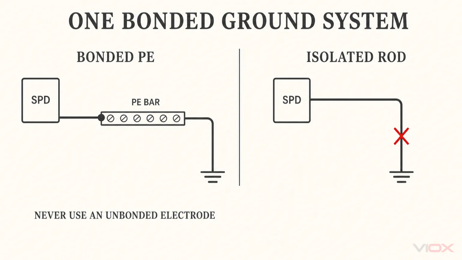
Multiple electrodes are not inherently wrong. The problem is unbonded, separately referenced electrodes. A properly designed grounding electrode system can contain multiple interconnected electrodes while maintaining the required common bonding reference.
Does an SPD Need a Dedicated Ground Wire?
It needs the grounding or bonding connection specified by its manufacturer. Some devices have a dedicated PE conductor or terminal; others connect through an approved integrated panel arrangement.
“Dedicated” describes the device’s intended connection—not permission to bypass the building’s protective bonding system, install an independent rod, or create a separate neutral-ground bond.
Why Lead Length Can Increase Let-Through Voltage
An SPD’s published voltage protection level is established at the device under defined test conditions. The installed voltage at protected equipment can be higher because surge current through connecting conductors produces additional voltage drop.
The governing relationship is:
Additional transient voltage ≈ conductor inductance × rate of change of surge current
ΔU ≈ L × di/dt
This is a conceptual relationship, not a universal prediction. Actual conductor geometry, surge waveform, current distribution, coupling, connection mode, and installation layout determine the result.
Schneider Electric explains that longer SPD connections increase inductive voltage drop and recommends the shortest practical routing without unnecessary bends. DEHN’s SPD technical FAQ discusses a 0.5 m total connection-path criterion in a particular protection-level context. That value must be interpreted with the applicable product instructions, installation framework, system design, and protected-equipment withstand—not as a universal legal limit for every SPD worldwide.
Measure the Complete Connection Path
The important route is the path between the protected conductors, the SPD, any required external disconnection or backup protection, and the approved PE connection.
Protected line or bus → required backup device → SPD → bonded PE terminalA short grounding lead alone does not compensate for a long phase conductor. Conversely, a long building grounding-electrode conductor does not automatically mean a panel SPD must bypass its local bonded grounding bar.
Practical layout improvements include locating the SPD near the protected bus and appropriate PE terminal, avoiding unnecessary loops, following approved routing methods, and selecting panel-compatible equipment when available. Conductor size, terminal torque, mechanical protection, conduit use, and spacing must follow the manufacturer and local installation rules. There is no universal ban on metallic conduit and no universal 12-inch separation rule for all SPD conductors.
For the complete conductor-routing and installation procedure, see the SPD wiring and installation guide.
Main Panel vs. Subpanel: Where Neutral and Ground Belong
The permitted relationship between neutral and protective earth depends on the supply arrangement, service equipment, grounding topology, and local code.
In many North American installations, the main bonding connection occurs at the service equipment or another location explicitly permitted by the applicable rules. Downstream subpanels generally maintain isolated neutral bars and separately bonded equipment-grounding bars.
An SPD installed at a subpanel must not be used to create an extra neutral-to-ground bond. Follow its wiring diagram and identify which conductors correspond to its declared protection modes. A device can contain an N-to-PE protection mode without authorizing a permanent external neutral-ground jumper.
For IEC-based installations, the correct connection also depends on the earthing arrangement:
| System arrangement | SPD grounding implication | What requires verification |
|---|---|---|
| TN-S | Neutral and PE are separate conductors at the SPD location. | Correct protection modes, PE continuity, and no unauthorized N-PE connection. |
| TN-C-S | A combined PEN conductor exists upstream, with separation at the designed point. | Correct installation side of the PEN split and compliance with the actual network arrangement. |
| TT | The installation uses its own earth-electrode arrangement as part of the designed protective system. | Suitable SPD configuration, N-PE behavior, residual-current-device coordination, and applicable installation rules. |
| IT, ungrounded, or resistance-grounded | Line-to-earth behavior and fault conditions differ from solidly grounded systems. | SPD suitability specifically declared for the actual topology and possible temporary overvoltages. |
A TT installation’s local electrode is part of its designed grounding system. It is not permission to connect one SPD to a separate, isolated electrode outside the installation’s required bonding arrangement.
Five Checks for a Suspected SPD Grounding Problem
1. Confirm the Device Status Without Opening Live Equipment
Look for the manufacturer-defined status window, alarm contact, display, or monitoring message where it is safely visible. A failed indicator, missing module, tripped associated protective device, damaged enclosure, heat discoloration, or burning odor warrants professional evaluation.
Do not interpret a green indicator as proof that the grounding system, connection geometry, or device selection is correct. The indicator generally reports a device-specific condition, not the integrity of the entire installation.
For replacement and aging, see industrial SPD lifespan and MOV aging.
2. Trace the Intended Bonding Reference
A qualified electrician should confirm that the SPD’s PE terminal connects to an approved bonded point and that the relevant panel, equipment frames, service interfaces, and grounding electrode system follow the applicable grounding and bonding design.
Inspect for loose or damaged connections, corrosion, missing bonding jumpers, unapproved terminal sharing, and accidental connections to isolated metalwork. Visual appearance alone cannot establish electrical continuity.
3. Evaluate the Entire SPD Connection Geometry
Identify the protected line connection, required external protective device, SPD terminals, and PE return. Assess total connection length, unnecessary bends, loops, and panel layout against the product instructions and applicable installation guidance.
If the existing arrangement is unusually long, relocation, an approved alternate bonded termination, a more suitable panel-compatible SPD, or an additional coordinated downstream device may be preferable. Do not independently re-route energized conductors or alter protective bonding.
4. Match the SPD to the Actual Electrical System
Verify system voltage, earthing configuration, protection modes, maximum continuous operating voltage, voltage protection level, prospective fault current, and required external fuse or breaker.
An SPD designed for a solidly grounded system may not be suitable for an ungrounded or resistance-grounded system. Schneider’s installation documentation specifically distinguishes grounding configurations when determining device suitability.
Use how to read an SPD datasheet for model-specific verification and the Type 1 vs. Type 2 vs. Type 3 SPD comparison when classification or installation position is unclear.
5. Check Other Entry Paths and Coordination
Power, Ethernet, coaxial, instrumentation, and inter-building conductors can introduce different surge paths. Where protection is needed, those interfaces should reference the installation’s coordinated bonding arrangement while using protectors suitable for their own circuit function.
A panel power SPD does not replace a correctly selected signal-line SPD. Likewise, a point-of-use device should be coordinated with upstream protection and installed according to its own listing, instructions, and market rules—not a universally assumed spacing distance.
For data and control interfaces, use the signal surge protector selection guide.
Does Ground Resistance Determine Whether an SPD Works?
Grounding-electrode resistance can matter for the wider installation design and must satisfy the applicable code, protective scheme, and engineering requirements. However, a soil-resistance measurement does not by itself establish effective surge protection.
DEHN states that no single specific earth-resistance value is universally required for SPD earthing and emphasizes equipotential bonding. Avoid claims such as “every SPD requires less than 5 ohms” or “25 ohms guarantees protection” unless a specific project, jurisdiction, manufacturer, or engineered system explicitly imposes that criterion.
The relevant questions are different:
- Is the protective grounding and bonding system compliant and continuous?
- Is the SPD connected at an approved point?
- Are protected interfaces referenced to the coordinated bonding system?
- Is the connection short enough for the required installed protection level?
- Is the device appropriate for the system topology and available fault current?
- Is additional downstream protection necessary for sensitive equipment?
When to Stop and Call a Qualified Electrician
Do not open energized service equipment, defeat covers, install a ground rod, disconnect a grounding conductor, move a neutral-ground bond, or test live terminals unless qualified and authorized.
Request immediate professional assessment when there is a burning odor, visible overheating, damaged conductors, an unbonded electrode, unexplained neutral-ground connections, a failed SPD indicator, recurrent equipment damage, or uncertainty about the actual grounding topology.
Give the electrician the SPD model, installation location, panel type, system voltage, known grounding arrangement, status indication, and details of the affected equipment. Request confirmation of the manufacturer’s wiring diagram, approved bonding point, total connection path, backup protection, fault-current compatibility, and any necessary coordinated downstream protection.
An effective panel surge protector is not defined by the nearest piece of soil. It is defined by a correctly selected SPD connected through a safe, short, verified path to the installation’s common, properly bonded protective system.