On this page
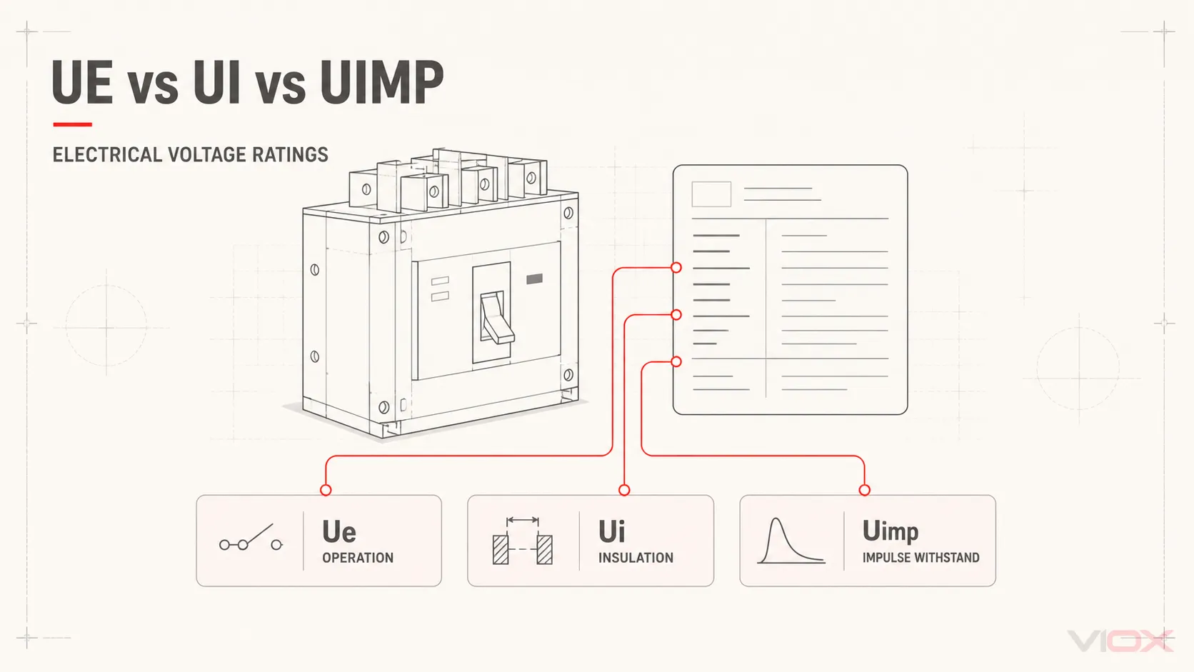
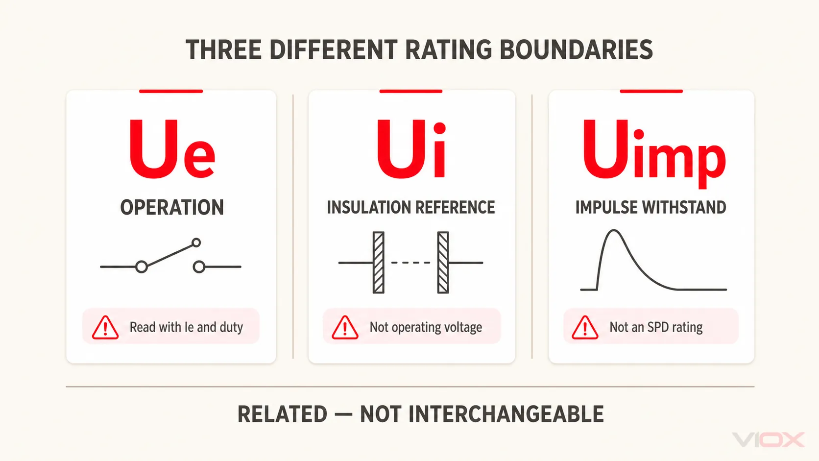
Ue is the rated operational voltage at which a device’s operating performance is declared. Ui is the rated insulation voltage used as a reference for insulation coordination. Uimp is the rated impulse withstand voltage under specified transient test conditions. These ratings are not interchangeable, and a higher Ui or Uimp does not authorize operation above the device’s declared Ue.
When reading a circuit breaker, contactor, switch, relay, or terminal-block datasheet, treat the three values as answers to different engineering questions. Then verify the product-specific standard and the other ratings tied to the intended application.
Ue vs Ui vs Uimp: Quick Comparison
| Marking | Full term | Engineering question it answers | What it does not prove by itself |
|---|---|---|---|
| Ue | Rated operational voltage | At what voltage are the device’s relevant operating characteristics declared? | Current capacity, utilization category, breaking capacity, AC/DC suitability, or application fit at every lower voltage |
| Ui | Rated insulation voltage | What voltage value is used as a reference for specified dielectric tests and creepage distances? | Permission to operate continuously at Ui, expected service life, or a universal insulation safety margin |
| Uimp | Rated impulse withstand voltage | What peak impulse voltage can the insulation withstand under the applicable standard’s specified test conditions? | Surge clamping voltage, absorbed surge energy, lightning current rating, or an SPD function |
The values must be read together, but they do not form one interchangeable scale. Ue and Ui are normally expressed in volts, while Uimp is expressed as a peak value in kilovolts under a defined impulse test. Comparing their printed numbers without considering their different meanings is not a valid selection method.
What Does Ue Mean in Electrical Equipment?
Ue means rated operational voltage. In the IEC 60947 framework, it is associated with the equipment’s application and operating performance. It must therefore be read with the characteristics declared at that voltage—not as an isolated maximum-voltage number.
Depending on the product, the related declarations may include:
- rated operational current, Ie;
- AC or DC operation and frequency;
- utilization category, such as an applicable contactor or switch category;
- making and breaking performance;
- short-circuit breaking capacity for a circuit breaker;
- pole configuration and connection arrangement.
For example, a contactor datasheet may declare different operational currents for different Ue values and utilization categories. A circuit breaker may declare different Icu or Ics values at different operational voltages. That is why a voltage number on its own cannot establish the complete operating capability.
For circuit-breaker terminology and device boundaries, see the VIOX guide to molded-case circuit breakers. The separate Icu, Ics, Icw, and Icm guide explains why short-circuit ratings must also be read at their stated voltage and test conditions.
Does Ue Have to Equal the System Voltage?
The selected equipment must have a declared operational rating suitable for the actual circuit voltage. An identical or higher printed Ue may be part of that check, but a higher Ue alone does not prove that the device is suitable.
Before using a device on a lower-voltage circuit, verify the exact datasheet for:
- the intended AC or DC system;
- operational current at that voltage;
- utilization category or load type;
- making, breaking, or short-circuit performance;
- frequency, pole arrangement, and manufacturer instructions.
This prevents a common mistake: assuming that one high Ue value automatically carries every other performance declaration across all applications.
What Is Rated Insulation Voltage Ui?
Ui means rated insulation voltage. It is the voltage value to which specified dielectric test voltages and creepage-distance requirements are referred under the applicable equipment framework.
Ui is therefore an insulation-coordination reference. It is not the voltage at which the equipment is automatically permitted to operate continuously. If a device is marked Ue 400 V and Ui 800 V, the 800 V Ui marking does not turn it into an 800 V operational device.
For equipment declaring both values, the maximum declared Ue should not exceed Ui. That relationship does not create a universal rule that Ui must be a fixed multiple of the system voltage. The appropriate values and verification method depend on the applicable product standard, circuit, environment, and equipment construction.
Does Ui Tell You the Exact Dielectric Test Voltage?
Not by itself. Ui provides a reference used by the applicable standard, but the exact test voltage, test points, conditioning, duration, and acceptance criteria must be taken from the relevant product standard and test table.
Avoid applying a simplified formula such as 2 × Ui + 1000 V to every breaker, contactor, relay, terminal block, or assembly. Products can fall under different standards and test sequences. A dielectric withstand test is also not automatically an accelerated simulation of years of insulation aging; it verifies performance under its stated proof conditions.
How Does Ui Relate to Creepage Distance?
Creepage distance is measured along an insulating surface. Its required value can depend on the voltage across the insulation, pollution degree, insulating material group, and the applicable product or insulation-coordination standard. Ui is used as a reference in relevant low-voltage equipment frameworks, but it should not replace the complete creepage and insulation assessment.
The VIOX creepage and clearance guide explains why surface distance and distance through air use different design inputs.
What Does Uimp Mean?
Uimp means rated impulse withstand voltage. It is the peak value of an impulse voltage that the equipment insulation is declared capable of withstanding under specified test conditions.
Uimp is closely associated with insulation coordination and clearance requirements. The applicable selection can depend on factors such as the nominal supply system, overvoltage category, location in the installation, and conditions defined by the relevant standard. Do not select a value from a generic category table without confirming the table basis and the product standard.
What Does Uimp 8 kV Mean?
Uimp 8 kV means that the equipment insulation has a declared rated impulse withstand voltage of 8 kV peak under the applicable standard’s specified test conditions. It does not mean that the device starts clamping at 8 kV, absorbs a stated amount of surge energy, or interrupts lightning current.
An 8 kV Uimp marking is therefore not an alternative to a surge protective device. An SPD has its own application-specific declarations, such as continuous operating voltage, voltage protection level, discharge-current ratings, protection modes, and temporary-overvoltage behavior. See what a surge protective device does for that separate protection function.
How Ue, Ui, and Uimp Work Together
Use a three-boundary model instead of treating the ratings as a numerical ladder:
| Boundary | Start with | Then verify |
|---|---|---|
| Operational-performance boundary | Ue | Ie or In as applicable, AC/DC, frequency, utilization category, poles, switching duty, and breaking data |
| Insulation-reference boundary | Ui | Applicable dielectric requirements, creepage path, pollution degree, material and product-standard conditions |
| Impulse-withstand boundary | Uimp | Applicable impulse requirement, overvoltage category, clearance, altitude or service conditions, and installation framework |
Passing or declaring one boundary does not replace another. A high Ui does not compensate for an inadequate Ue. A high Uimp does not prove operational switching capacity. A suitable Ue does not establish short-circuit performance unless the relevant current rating at that Ue is also verified.
How to Read Ue, Ui, and Uimp on a Datasheet
Consider an illustrative MCCB label showing:
- Ue: 415 V AC;
- Ui: 800 V;
- Uimp: 8 kV;
- a table of Icu and Ics values by operational voltage;
- IEC 60947-2 as the referenced product standard.
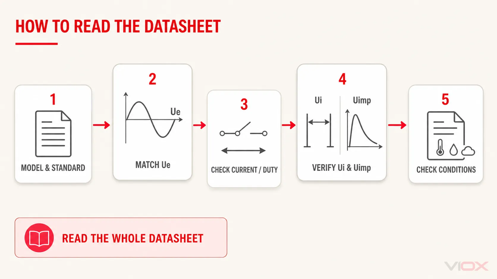
These values are illustrative, not a recommendation for a particular installation. Read them in this order.
1. Confirm the Device and Product Standard
Identify the exact model and the standard under which its characteristics are declared. IEC 60947-1 supplies general rules when invoked by the relevant low-voltage switchgear or controlgear product standard. A circuit breaker, contactor, terminal block, relay, and complete assembly can have different product-specific requirements.
2. Match the Circuit to the Declared Ue
Confirm that 415 V AC is an appropriate operational declaration for the actual system voltage and connection. Do not use the 800 V Ui value as operating permission.
3. Read Current and Switching Data at That Ue
Use the Icu and Ics values declared at 415 V, not values printed for another voltage. For a contactor or switch, use the operational current and utilization category corresponding to the actual voltage and load duty.
4. Interpret Ui as an Insulation Reference
The Ui 800 V marking identifies the declared insulation-voltage reference. It does not state that the MCCB can switch or operate continuously at 800 V.
5. Interpret Uimp as a Defined Withstand Rating
The Uimp 8 kV marking concerns the specified impulse-withstand boundary. Confirm that it meets the requirement established for the installation and applicable standard. Do not compare it with an SPD’s clamping or discharge ratings.
6. Check the Conditions Attached to Every Declaration
Complete the review with the pole configuration, frequency, ambient and mounting conditions, isolation function where required, terminals and conductors, accessories, and manufacturer instructions. A label summary cannot replace the complete datasheet.
Ue, Ui, and Uimp Specification Checklist
| Check | Evidence to obtain | Reject or clarify when |
|---|---|---|
| Exact equipment identity | Manufacturer, model, variant, poles, accessories | The quotation identifies only a family or frame size |
| Applicable standard | Current datasheet and stated product standard | A generic “IEC compliant” statement replaces a specific declaration |
| Operational voltage | Ue with AC/DC, frequency, and circuit arrangement | Only Ui or an unrelated maximum voltage is provided |
| Operational performance | Ie, utilization category, making/breaking or Icu/Ics data at the intended Ue | Current or breaking data are listed only at another voltage |
| Insulation reference | Declared Ui and the relevant product-standard conditions | Ui is presented as continuous operating voltage |
| Impulse withstand | Declared Uimp and applicable installation requirement | Uimp is described as SPD clamping or surge-energy capacity |
| Environmental conditions | Pollution, altitude, temperature, enclosure, and mounting conditions where applicable | Ratings are quoted without the conditions that limit them |
| Verification documents | Datasheet, test or conformity evidence required by the project | Marketing language is offered instead of model-level documents |
A standard declaration is not automatically proof of third-party certification. If a project requires certification, a test report, or a specific conformity document, verify that evidence for the exact catalog number and target market.
Common Misinterpretations
| Misinterpretation | Correct reading |
|---|---|
| “Ui 800 V means the device can operate at 800 V.” | Continuous operation must stay within the declared Ue and all associated conditions. |
| “Uimp 8 kV means the device protects downstream equipment from 8 kV surges.” | Uimp is an insulation withstand declaration, not a voltage-clamping function. |
| “A 690 V Ue device is automatically suitable for every 400 V application.” | Verify AC/DC, current, category, breaking duty, poles, frequency, and instructions at the intended voltage. |
| “A larger Ui always gives longer service life.” | Ui is an insulation reference, not a universal life or reliability score. |
| “Ue, Ui, and Uimp can be compared by number.” | They represent different conditions and engineering boundaries. |
Standards Scope: What Each Reference Contributes
| Reference | Relevant scope | What it does not establish on its own |
|---|---|---|
| IEC 60947-1:2020 | General rules and common requirements for low-voltage switchgear and controlgear when required by the relevant product standard | Suitability or certification of a particular catalog number |
| IEC 60947-2:2024 | Product requirements for circuit breakers within its stated voltage and application scope | Requirements for every contactor, relay, terminal block, or assembly |
| IEC 60664-1:2020+AMD1:2025 | Insulation-coordination principles, clearances, creepage distances, solid insulation, and related testing methods within its scope | A complete product selection or installation approval by itself |
| Manufacturer datasheet and instructions | Model-specific declarations, combinations, limitations, and installation conditions | Compliance with unstated project, jurisdiction, or system requirements |
Use the edition required by the project or jurisdiction. A newer publication date does not automatically replace the contractual or legally adopted edition for every market.
Frequently Asked Questions
What is the difference between Ue and Ui?
Ue is the rated operational voltage associated with declared operating performance. Ui is the rated insulation voltage used as a reference for specified dielectric tests and creepage distances. Ui must not be used as permission to operate above the declared Ue.
Can equipment operate continuously at Ui?
Not unless that voltage is also covered by an appropriate Ue declaration and all associated operating characteristics. Ui alone is not a continuous operating-voltage rating.
What does Uimp 8 kV mean on an MCCB?
It means the MCCB insulation has a declared rated impulse withstand voltage of 8 kV peak under the applicable standard test conditions. The MCCB’s operational voltage, current and short-circuit performance must still be checked separately.
Is Uimp the same as an SPD voltage rating?
No. Uimp is an equipment insulation-withstand declaration. An SPD is selected using its own voltage, discharge, protection-level, system and application parameters.
Can a device with Ue 690 V always be used on a 400 V system?
Not from the Ue number alone. Confirm that the manufacturer declares suitable performance for the intended voltage, AC or DC system, load, current, utilization category, poles, frequency, and switching or breaking duty.
The Correct Reading Rule
Read Ue for operational performance, Ui for the insulation reference, and Uimp for specified impulse withstand. Then check the applicable product standard and every performance value tied to the intended voltage. This approach is more reliable than choosing the device with the largest printed voltage numbers.
When evaluating an MCCB, use the complete product datasheet and project requirements before comparing models in the VIOX MCCB range. For switching applications, apply the same rating discipline to the exact device and duty when reviewing AC contactors.