On this page
There is no universal formula that converts panel amperage into a surge protective device (SPD) kA rating. A 2,000 A switchboard does not automatically require a 200 kA SPD, and a 100 A panel does not automatically need a smaller surge rating. Load current and surge current describe different events.
To select an SPD kA rating, first identify what the quoted current actually means—In, Imax, Iimp, per mode, per phase, or per pole—and the test waveform behind it. Then evaluate the installation position, expected exposure, upstream and downstream protection, consequence of losing protection, voltage protection level, available fault current, and the evidence supplied for the exact product.
The practical principle behind the Gatekeeper Strategy is sound: do not buy the largest headline number for every panel, but do not underspecify a difficult-to-replace SPD at an exposed or critical position. Allocate capacity where the system evidence and operational consequence justify it.
Key Takeaways
- Panel ampere rating does not calculate the required SPD kA rating.
- A larger surge-current number does not automatically mean a lower Up or voltage protection rating (VPR).
- kA capacity is not a fixed service-life rating. You cannot convert it into a guaranteed number of surges or years.
- Compare In with In, Imax with Imax, and Iimp with Iimp under the same standard, waveform, type, and declaration basis.
- Confirm whether the rating is stated per mode, per phase, per pole, or for the complete SPD assembly.
- Installation position matters, but there is no universal kA table that fits every service entrance and branch panel.
- Short-circuit current rating (SCCR) is a separate safety check against available fault current; it is not surge-current capacity.
- Replacement access, indication, remote signaling, and documented coordination may be as important as buying another increment of kA.
Start by Identifying Which kA Number You Are Comparing
An SPD quotation that says only “40 kA,” “100 kA,” or “200 kA” is incomplete. The number has meaning only when the associated rating, waveform, protection mode, and product standard are stated.
| Marking or declaration | What it normally describes | Selection use | Comparison boundary |
|---|---|---|---|
| In | Nominal discharge current under defined test conditions | Repetitive-duty comparison within the applicable SPD class | Compare only under the same standard and waveform |
| Imax | Maximum discharge current, commonly associated with an 8/20 µs current waveform for IEC Type 2 SPDs | Maximum tested discharge-current headroom | Do not treat as normal repeated duty or guaranteed life |
| Iimp | Impulse discharge current used for Type 1 lightning-current duty in IEC practice | Type 1 impulse-current selection | Do not rank it numerically against Imax without accounting for the different waveform and duty |
| Per mode | Capacity declared for one protection path, such as L–N or L–PE | Mode-level comparison | Confirm which modes are present and rated |
| Per phase | Capacity declared for the paths associated with one phase under the manufacturer’s stated convention | Phase-level product comparison | Do not assume every manufacturer calculates it identically |
| Per pole | Capacity assigned to one protective pole or module | Modular SPD comparison | Confirm how poles form the complete protection mode |
| SCCR | Suitability for a stated prospective short-circuit current under specified conditions | Fault-current safety check | Never substitute it for In, Imax, or Iimp |
For the detailed definitions and test-duty distinction, use the VIOX guide to Imax versus In in an SPD. This page focuses on what to do with those ratings when selecting capacity for a real distribution position.
Why 25 kA Iimp is not “smaller” than 40 kA Imax
A common procurement error is to compare the numbers while ignoring the waveforms. A Type 1 rating expressed as Iimp with a 10/350 µs waveform and a Type 2 rating expressed as Imax with an 8/20 µs waveform represent different test duties. The peak numbers alone do not establish which device has the greater application capability.
First decide whether the installation requires Type 1, Type 2, or Type 3 duty. Then compare products within that requirement. The VIOX Type 1 versus Type 2 versus Type 3 guide owns the full type and waveform decision.
What a Higher kA Rating Does—and Does Not Prove
Within a comparable product family, additional surge-current capacity can provide more design margin for severe or repeated surge exposure. It may be achieved through larger protective components, parallel paths, a different internal architecture, or another design choice. However, the headline capacity alone does not disclose how the current shares internally, how the protective elements age, or when the complete SPD will reach end of life.
A higher kA value does not by itself prove:
- a lower Up or VPR;
- a faster response;
- a particular number of survivable events;
- a ten-, fifteen-, or twenty-year service life;
- better thermal disconnection;
- a higher SCCR;
- correct voltage or earthing-system compatibility;
- successful coordination with another SPD;
- a valid certification for the target market.
This is why “kA equals lifespan” is too strong. Capacity may contribute to robustness, but actual life depends on the magnitude, waveform, duration, and frequency of stresses; temporary overvoltage; ambient conditions; internal construction; protective disconnection; and the installation itself. A manufacturer’s verified repetitive-duty or endurance evidence is more useful than a life estimate inferred from Imax alone.
The Gatekeeper Capacity Review
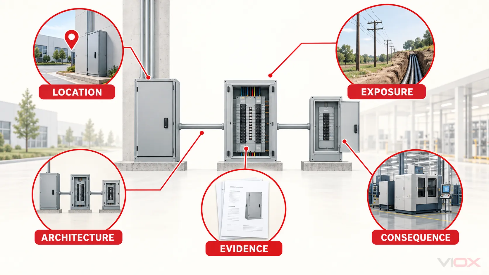
The original Gatekeeper idea becomes reliable when it is treated as a five-part review rather than a fixed kA ladder.
1. Location: Where will the SPD be installed?
Identify whether the device is at the service entrance, main switchboard, distribution board, branch or control panel, or directly associated with critical equipment. Location changes the surge environment, the available fault current, the upstream protection already present, and the difficulty of replacement.
IEEE C62.41.2 characterizes surge environments in low-voltage AC circuits using standardized waveforms and location-related stress parameters. It does not create a universal rule that every panel at one location must use one commercial kA size. The selected rating still has to be tied to the project and product evidence.
2. Exposure: What surge sources can reach this position?
Review the supply and the installation rather than assuming every main panel receives the same “daily beating.” Relevant inputs include:
- overhead or underground incoming supply;
- local lightning exposure and the project’s lightning-risk assessment;
- presence of an external lightning protection system;
- long outdoor feeders or circuits leaving the structure;
- utility and capacitor-bank switching;
- large inductive loads, contactors, motors, drives, and other local switching sources;
- conductive services entering the building;
- previous event records, power-quality monitoring, or site-specific disturbance evidence.
Do not invent an annual event count when the facility has no monitoring data. Record the exposure evidence that actually exists and state uncertainty where it does not.
3. Consequence: What happens if protection is unavailable?
The same electrical exposure can justify different purchasing decisions in different facilities. A replaceable SPD in an accessible noncritical panel is not the same operational problem as an SPD serving a process that cannot be stopped without a controlled shutdown.
Assess:
- value and sensitivity of downstream equipment;
- cost and duration of a planned shutdown;
- whether the SPD can be isolated and replaced without stopping the whole facility;
- whether spare cartridges or complete replacement units are stocked;
- whether loss of protection is visible locally;
- whether remote indication is needed for an unattended or distributed site.
Capacity is only one way to manage consequence. Replaceable modules, redundancy where supported, visual status, remote contacts, accessible mounting, and a documented replacement procedure may produce more value than selecting by the largest kA number alone. For unattended panels, see the VIOX guide to SPD remote signaling.
4. Architecture: What protection exists upstream and downstream?
An upstream SPD does not make every downstream SPD unnecessary. Downstream panels can still see residual incoming stress and locally generated transients. Conversely, adding several unrelated SPDs does not prove they are coordinated.
At the capacity-selection stage, record:
- the SPD type and rating at each upstream position;
- the distance and conductor path between stages;
- the downstream equipment impulse-withstand requirement;
- the Up or VPR of each candidate;
- any manufacturer coordination instructions;
- power, signal, data, and control-line entry paths.
Do not calculate a fixed sequence such as “20 kA becomes 2 kA and then 0.3 kA” without a verified system model or test. The current division and resulting voltage depend on source and wiring impedance, SPD characteristics, connection length, and protection modes. Use the VIOX SPD coordination and cascading guide for the full multi-stage verification task.
5. Evidence: What can the exact model prove?
A capacity decision is not complete until it resolves to a product record. Request the exact datasheet, installation instructions, and market-specific certification record where certification is required.
At minimum, verify:
- exact model and configuration;
- AC, DC, or PV application;
- nominal system voltage and Uc/MCOV;
- Up or VPR and its protection modes;
- In, Imax, or Iimp with the applicable test basis;
- per-mode, per-phase, per-pole, or assembly declaration;
- Type 1, Type 2, Type 3, or the applicable IEC class/test class;
- SCCR or the applicable short-circuit withstand information;
- required backup fuse or circuit breaker;
- internal disconnector and status indication;
- environmental and enclosure conditions;
- certificate scope for the exact model, voltage, and configuration.
The VIOX SPD datasheet guide provides the complete label-reading sequence. Blank or ambiguous quotation fields should remain unresolved rather than being filled with assumptions.
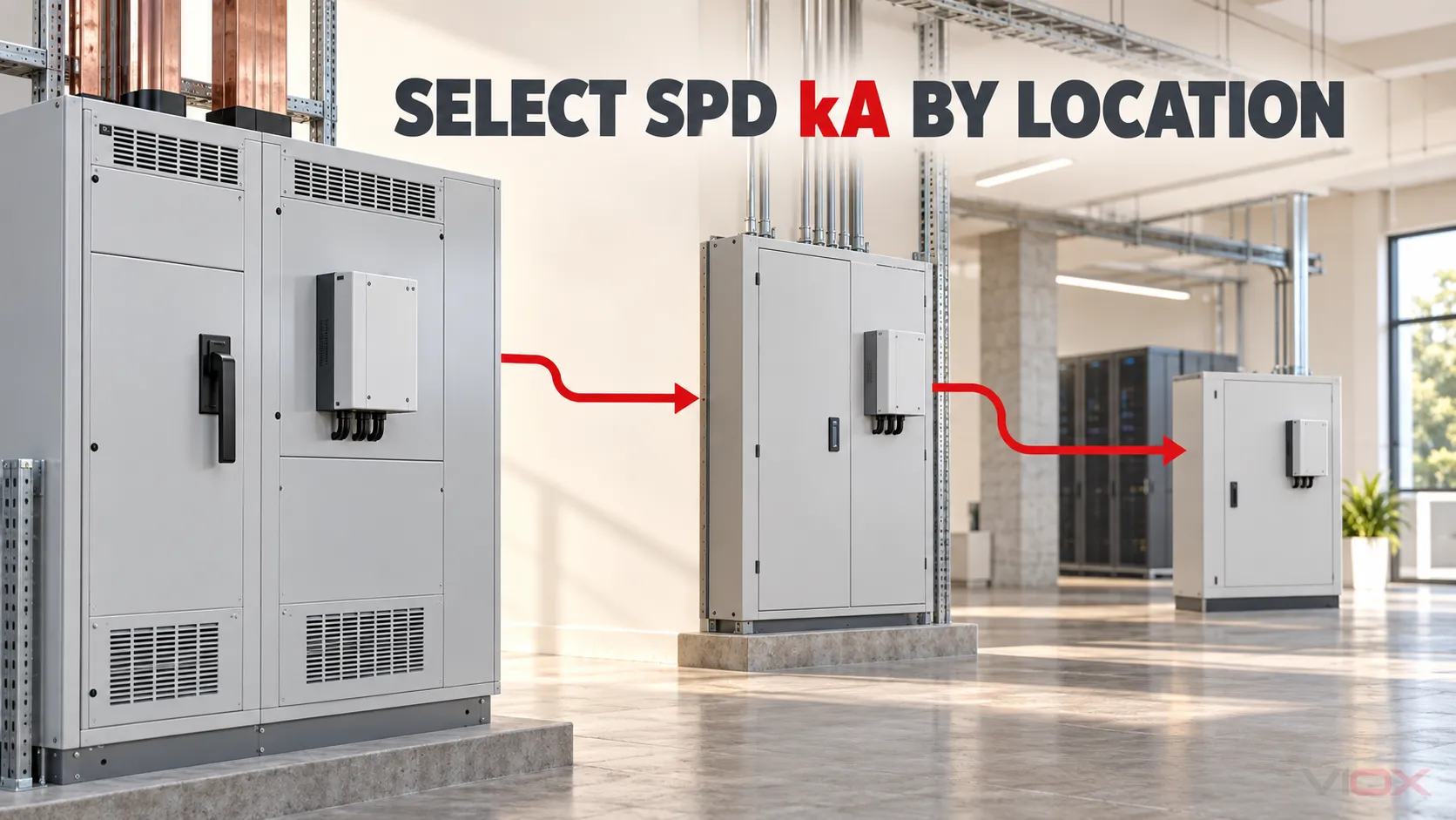
Location Changes the Questions, Not Just the Number
The following matrix preserves the useful main-versus-branch logic without turning one supplier’s product tiers into a universal engineering rule.
| Distribution position | Exposure questions | Operational questions | Capacity decision | Evidence to request |
|---|---|---|---|---|
| Service entrance or main switchboard | Is the supply overhead? Is an external LPS present? What does the risk assessment require? | Is replacement difficult or disruptive? Is remote status necessary? | Select the required SPD type first, then choose documented current capacity with appropriate margin for the assessed exposure | Type/test class, Iimp or applicable current rating, Up/VPR, Uc/MCOV, SCCR, backup protection, installation conditions |
| Main distribution or major subdistribution board | What upstream SPD exists? Are long feeders or outdoor circuits connected? Are large switching loads present? | Which loads are affected by isolation of this board? | Compare like-for-like products and account for both residual upstream stress and local surge sources | In/Imax or applicable duty, Up, protection modes, coordination evidence, replaceability and indication |
| Branch or control panel | Is the panel remote from the main board? Does it serve motors, drives, solenoids, or sensitive controls? | Can the SPD be replaced during routine maintenance? | Do not automatically copy the main-board rating; select for the local exposure, upstream architecture, and equipment consequence | Correct Type, Uc, Up, In/Imax, backup OCPD, lead-length and installation instructions |
| Critical equipment or point of use | What transient can arrive through power, data, or control conductors? What is the equipment withstand level? | What is the downtime or restart consequence? | Prioritize voltage protection, coordination, interface compatibility, and maintainability; a larger power-SPD kA number alone may not solve the task | Up/VPR, Type 3 or equipment-level coordination evidence, signal-line compatibility, status and replacement method |
The matrix intentionally contains no mandatory 150–300 kA or 50–100 kA bands. Commercial ranges vary, and a location label cannot replace a risk assessment, project specification, or manufacturer application guidance.
How to Compare Two SPD Quotations Correctly
Suppose one quotation offers “50 kA per mode” and another offers “100 kA per phase.” The second number looks larger, but the quotations are not yet comparable.
Use this normalization sequence:
- Match the electrical system. Confirm nominal voltage, wiring configuration, earthing arrangement, and AC/DC application.
- Match the SPD type and standard. Do not compare a Type 1 Iimp value with a Type 2 Imax value as if they were the same test.
- Match the rated-current name. Compare In with In, Imax with Imax, or Iimp with Iimp.
- Match the waveform and test basis. A peak value without its duty is incomplete.
- Normalize the declaration basis. Identify every protection mode and determine whether the published value is per mode, per phase, per pole, or for the complete assembly.
- Compare voltage protection. Check Up or VPR for the required modes. More current capacity does not compensate for an unsuitable protection level.
- Check fault-current suitability separately. Compare the marked SCCR and required upstream OCPD with the available fault current.
- Compare maintainability and evidence. Review indication, remote contacts, replaceable modules, installation limitations, and model-specific certification.
Quote-normalization worksheet
| Field | Candidate A | Candidate B | Acceptance decision |
|---|---|---|---|
| Exact model/configuration | Must be identifiable | ||
| Standard and SPD type | Must fit installation position | ||
| Uc/MCOV | Must fit actual system voltage and mode | ||
| Up/VPR by mode | Must fit equipment protection objective | ||
| In and waveform | Compare like with like | ||
| Imax and waveform | Compare like with like | ||
| Iimp and waveform, if applicable | Required where Type 1 duty applies | ||
| Per-mode/per-phase/per-pole basis | Must be normalized | ||
| SCCR and required OCPD | Must fit available fault current and stated conditions | ||
| Status/remote indication | Match maintenance plan | ||
| Certificate and model scope | Verify for target market |
This worksheet prevents a sales headline from becoming an engineering specification.
Do Not Confuse Surge-Current Rating with SCCR
Both values may be expressed in kA, but they answer different questions.
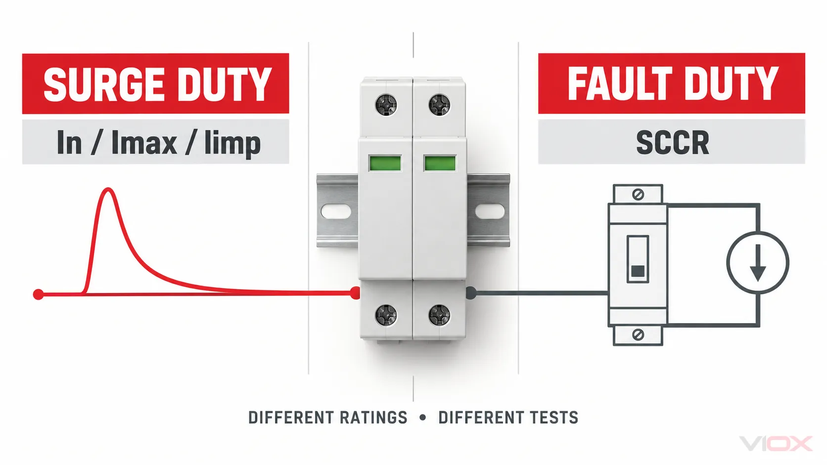
Surge-current ratings such as In, Imax, and Iimp describe defined transient-current duties. SCCR describes the prospective short-circuit current level at which the SPD is suitable for use under its stated conditions.
The SPD’s marked SCCR must be appropriate for the available fault current at the installation point. In North American applications, also verify the exact product listing, voltage, configuration, and any required upstream overcurrent protective device. The SPD does not necessarily interrupt the fault current by itself; the complete protection arrangement can include internal disconnection and an external fuse or circuit breaker.
UL’s public SPD verification material identifies voltage, frequency or phase/DC information, VPR, In, MCOV, and SCCR among the markings that must be checked for relevant listed devices. The NEMA Surge Protection Institute likewise describes SCCR in relation to the fault current available from the circuit. Neither value should be inferred from the product’s advertised maximum surge-current capacity.
For installation and regional-code boundaries, review the VIOX SPD installation requirements guide.
Use Lifecycle Cost as a Worksheet, Not a Promise
The budget logic behind the Gatekeeper Strategy remains useful, but it must use project inputs rather than invented product prices, event counts, or replacement intervals.
Calculate one replacement event as:
Replacement-event cost
= replacement SPD cost
+ electrician or maintenance labor
+ planned or unplanned outage hours × downtime cost per hour
+ restart, inspection, and validation cost
+ expedited logistics, if applicable
Then compare candidates on more than purchase price:
| Cost and continuity input | Why it matters |
|---|---|
| Initial product and installation cost | Establishes the upfront difference |
| Required shutdown boundary | Shows whether replacement affects one load, one panel, or the facility |
| Replaceable cartridge or complete-device replacement | Changes labor, spares, and access requirements |
| Local and remote status indication | Changes how quickly loss of protection can be detected |
| Documented endurance or repetitive-duty evidence | More defensible than estimating life from Imax |
| Spare availability and replacement lead time | Affects restoration risk |
| Inspection and verification procedure | Ensures a higher-priced device remains maintainable |
A higher-capacity SPD can be economically reasonable at a difficult or critical position, but the conclusion must come from documented product capability and site consequence—not from a guaranteed claim that a larger kA unit lasts ten times longer.
Final SPD kA Selection Checklist
Before approving the kA line on an SPD specification, confirm that:
- Panel ampere rating has not been used as the SPD surge-current calculation.
- The required SPD type or test class is established.
- Every kA value is identified as In, Imax, Iimp, SCCR, or another named rating.
- The waveform and standard behind the current rating are known.
- Per-mode, per-phase, per-pole, and complete-assembly declarations have been normalized.
- Uc/MCOV matches the actual system voltage and earthing arrangement.
- Up/VPR is suitable for the downstream equipment and protection objective.
- Service entrance, distribution, branch, and critical-load exposure have been assessed separately.
- Upstream and downstream SPDs have been recorded for coordination review.
- SCCR and the specified backup protective device suit the available fault current and product instructions.
- Replacement access, visual status, remote signaling, and spare strategy fit the consequence of losing protection.
- Ratings and certification claims are supported by the exact model documents.
The right outcome is not “the biggest kA everywhere.” It is a traceable selection in which the current rating, location, protection level, fault-current safety, maintainability, and product evidence all agree.
To compare available models, review the VIOX SPD product range. For application support, send the system voltage, wiring and earthing arrangement, installation position, upstream protection, available fault current, required market, and candidate datasheets to [email protected]. VIOX can then identify relevant published product information without treating a headline kA value as the complete specification.
Sources Reviewed
- IEC 61643-11:2025 — Low-voltage SPDs connected to AC low-voltage power systems
- IEEE C62.41.2 — Characterization of surges in low-voltage AC power circuits
- IEEE C62.72-2016 — Application of SPDs on the load side of service equipment
- UL — Verifying surge protective devices
- NEMA Surge Protection Institute — SPD safety and SCCR