

On this page
By VIOX Editorial Team. Sources checked: 3 November 2026.
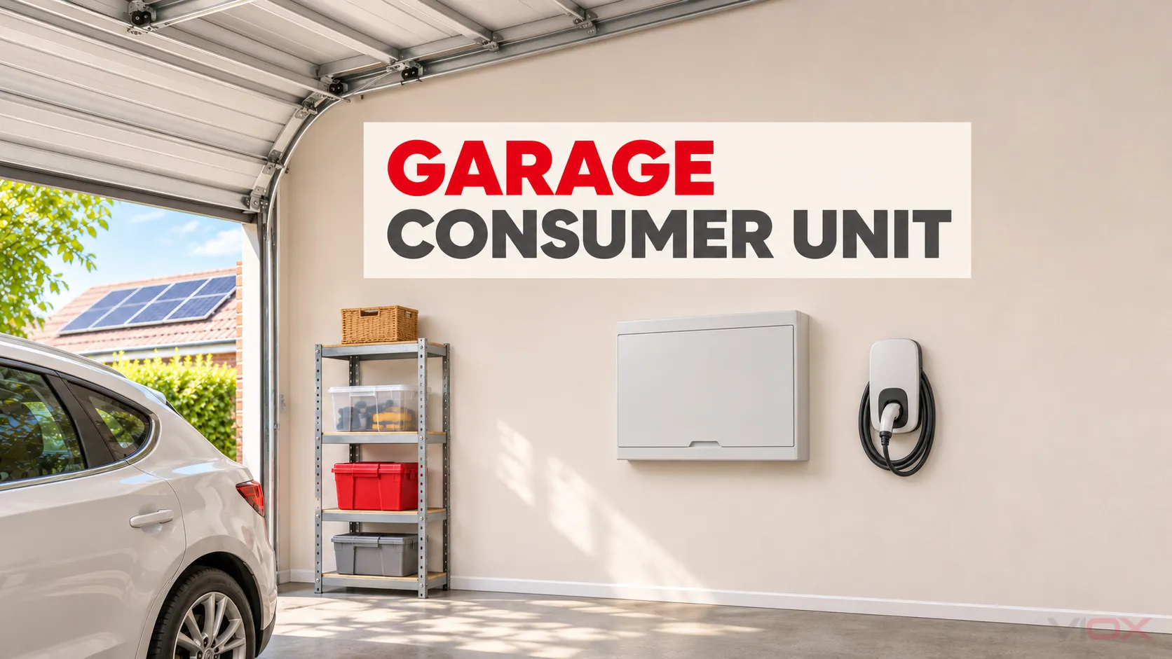
Choose a garage consumer unit by checking three separate limits: outgoing circuits, usable device space and electrical capacity. A small two-circuit board may serve lighting and sockets; adding an electric vehicle (EV) charging point, workshop equipment or solar photovoltaic (PV) generation requires a new circuit schedule and a supply/protection review. Extra empty ways do not increase the garage feeder’s capacity.
For a garage where losing the lighting during a socket fault matters, individual residual-current circuit-breakers with integral overcurrent protection (RCBOs) are worth specifying. Their benefit depends on coordination with upstream protection. EV and solar circuits also need equipment-specific checks: a generic “Type A, 30 mA” label does not settle every requirement.
This guide helps owners, electrical contractors and buyers prepare a UK domestic garage board specification. It is not a wiring procedure. As of November 2026, the current UK installation standard is BS 7671:2018+A4:2026; the IET confirms that the previous amendment transition ended on 15 October 2026. Historical guidance linked below explains individual principles; the designer must use the current standard and exact equipment instructions for the project. See the IET edition checker.
Start With the Supply and Circuit Schedule
A garage consumer unit is a local distribution assembly supplied from the installation’s upstream distribution. It provides the specified local isolation and outgoing circuit protection. A separate board is useful when several garage circuits need local distribution; the building’s name alone does not make one necessary.
Before ordering, ask the electrician to record the existing feeder, its protective device, the earthing arrangement and the expected loads. A long detached-garage supply needs particular attention to cable installation, voltage drop and fault protection.
| Design input | What it determines |
|---|---|
| Existing feeder cable, route, length and upstream protection | Whether the planned demand can be supplied; whether feeder alterations are needed |
| Supply voltage, phase and property capacity | Permitted equipment and maximum garage demand |
| Earthing and bonding arrangement | Fault protection, metal enclosure treatment and any EV-specific measures |
| Loads operating together | Demand assessment and any enforceable charging limit |
| Present and planned circuits | Outgoing ways, protective functions and expansion space |
| Solar inverter or battery connection | Reverse power flow, assembly loading, isolation and source warnings |
Use an actual circuit list rather than assuming every garage needs the same breaker kit:
| Circuit or interface | Selection questions |
|---|---|
| Lighting | Can a fault elsewhere leave the working area dark? What residual-current protection is required? |
| General sockets | What appliances will operate together, and what circuit arrangement suits them? |
| Door operator, freezer or other continuity-sensitive load | Is a separate circuit justified by the consequence of losing supply? |
| Fixed workshop equipment | What are its operating current, starting behavior and equipment instructions? |
| Dedicated EV charging circuit | What is the commissioned input current, residual-current arrangement and earthing solution? |
| PV inverter alternating-current (AC) connection | Is the garage board an approved connection point, and what generation can flow through it? |
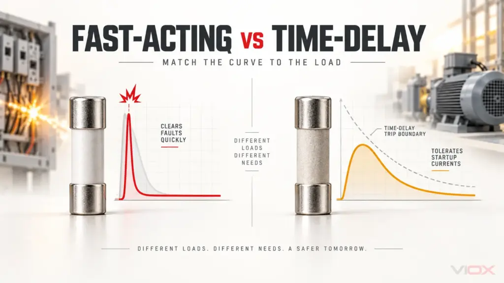
Do not select a larger trip curve merely because a compressor or welder trips an existing breaker. Cable protection and fault disconnection must remain effective after any change.
For the broader assembly-selection framework, use How to Choose a Distribution Box. This garage guide applies that framework to one specific location and its feeder, EV and generation constraints.
What Size Garage Consumer Unit Do You Need?
Separate outgoing ways from module space
An outgoing way is a circuit position. A module is a physical width used by the selected devices. Supplier descriptions such as “2-way” and “4-way” should be checked against the assembly drawing: they do not reliably tell you how much rail space remains after the incoming switch, residual-current devices and surge equipment.
| Planned use | Initial circuit requirement | What could make the board too small |
|---|---|---|
| Lights and general sockets | Two outgoing circuits | No room for the selected protection or future additions |
| Lights, sockets, fixed equipment and EV charging | Four outgoing circuits | EV protective functions, surge equipment and required spacing |
| The same four circuits plus a PV inverter AC connection | Five interfaces to accommodate | PV-compatible equipment, additional isolation and assembly loading limits |
These are illustrative circuit allocations, not prescribed installation designs. A dedicated equipment circuit or alternative generation connection can change the count.
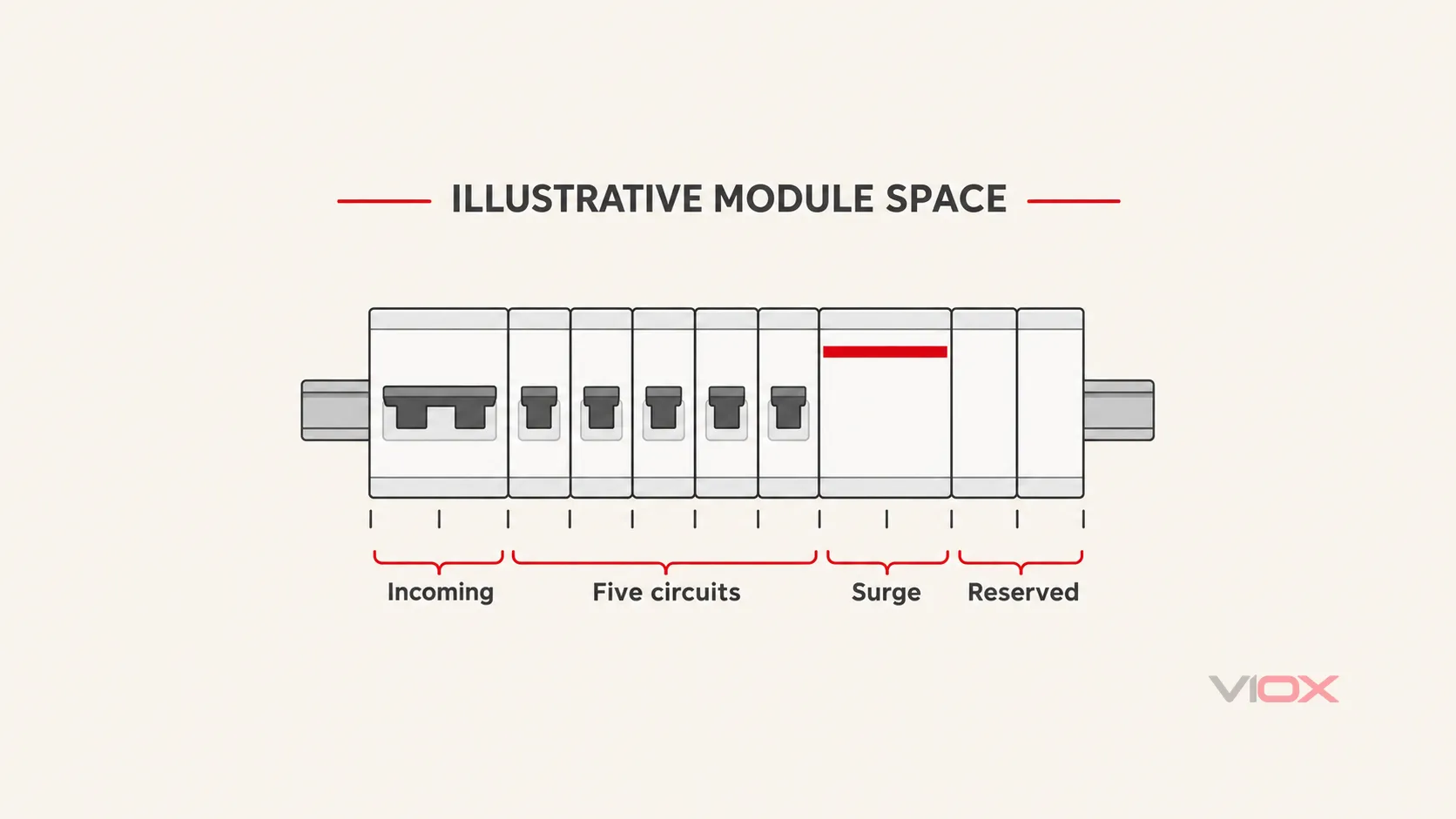
Module-space example: assume the proposed compatible assembly uses a two-module incoming switch, five one-module outgoing devices, a two-module surge protective device (SPD) and two reserved modules. The rail-space requirement is:
2 + (5 × 1) + 2 + 2 = 11 modulesThis arithmetic illustrates space budgeting only. Some RCBOs occupy more space; an EV arrangement may need separate devices; an SPD may require additional backup protection. Follow the actual assembly layout and thermal instructions before choosing the enclosure. Eleven modules does not mean eleven outgoing circuits.
Check amperes independently of enclosure size
Record the assembly rated current, busbar arrangement, incoming switch rating, feeder limit and outgoing circuit limits separately. A 100 A switch does not turn a 40 A garage feeder into a 100 A supply. Likewise, adding the ratings printed on every outgoing breaker is not a demand calculation.
Consider this hypothetical single-phase capacity screen: the electrician has established a 40 A permitted garage demand; the EV charging setting is 32 A; simultaneous non-EV demand is assessed as 12 A. With no solar generation:
Garage demand = 32 A + 12 A = 44 A 44 A exceeds the established 40 A limit Illustrative remaining EV allowance = 40 A − 12 A = 28 AThe result identifies a capacity conflict. It does not prescribe a 28 A charger setting or select a cable or breaker. Resolution may involve a supported lower charging setting, a properly designed load-curtailment system or a feeder upgrade. If controls protect the garage feeder, their monitoring point and failure behavior must actually protect that feeder; monitoring only total house demand may be insufficient.
Do not deduct expected daytime solar output to justify unrestricted charging. The garage must remain protected at night and when generation stops. The IET’s 2026 domestic EV design discussion highlights both sustained EV loading and the risk of assembly overload where additional sources are connected.
Shared RCD or Individual RCBO Protection?
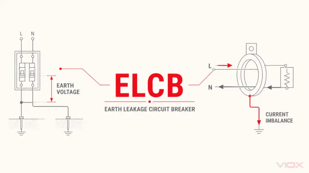
A residual current device (RCD) responds to residual current. A residual current operated circuit-breaker without integral overcurrent protection (RCCB) needs coordinated overload and short-circuit protection. A miniature circuit-breaker (MCB) provides overcurrent protection. An RCBO combines residual-current and overcurrent functions for its circuit.
| Arrangement | Practical consequence | Selection check |
|---|---|---|
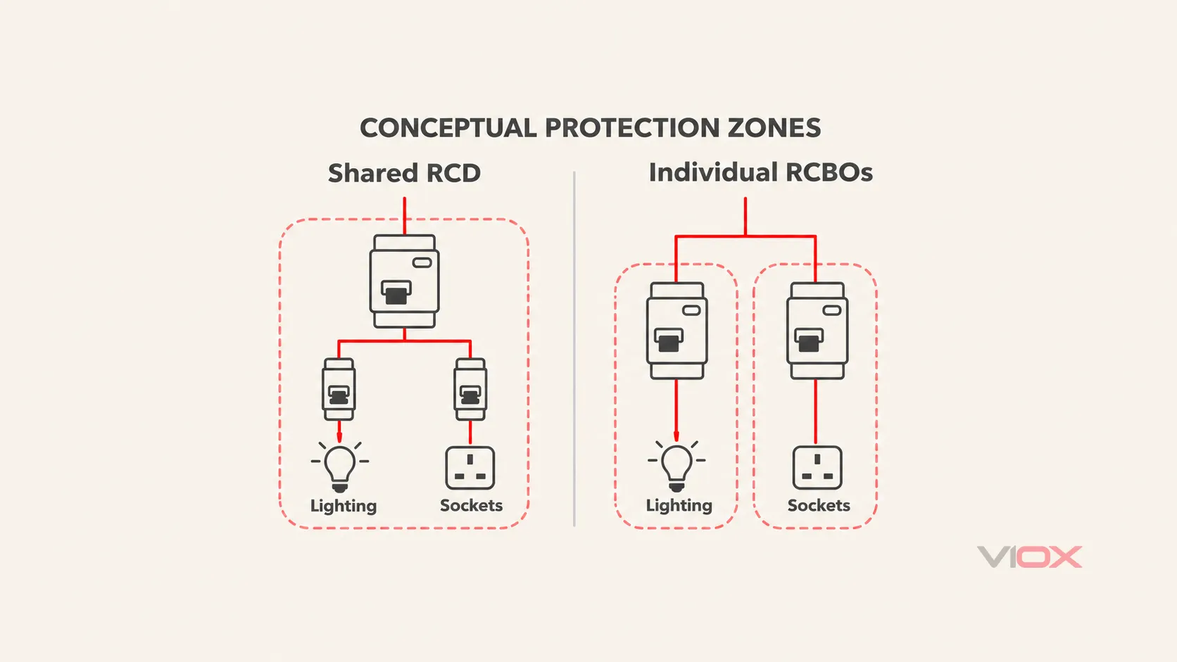
| Shared RCCB feeding several MCBs | A residual-current fault on one circuit can disconnect all circuits supplied through that RCCB | Consequence of losing lighting; combined leakage; RCCB overload protection; EV/PV compatibility |
| Individual RCBOs | Residual-current faults can be separated by outgoing circuit | Correct type, switched conductors, assembly compatibility and upstream selectivity |
Circuit-level RCBOs are particularly useful when a socket fault should leave garage lighting available. They cannot guarantee continuity if an upstream shared RCD also trips. Two ordinary instantaneous 30 mA RCDs in series do not establish selective operation simply because one is nearer the fault.
Check residual-current sensitivity, waveform type and pole switching as separate fields. The IET’s consumer-unit and protective-device FAQs discuss 30 mA additional protection for domestic lighting. Electronic loads and connected equipment also affect waveform selection; a Type AC device should not be assumed suitable for an EV/PV installation.
“Type B RCD” describes residual-current response. “B-curve MCB” describes an overcurrent trip characteristic. They are different specifications.
Plan the EV Circuit Around the Exact Charging Equipment
Provide a dedicated circuit for the intended Mode 3 electric vehicle supply equipment (EVSE). Obtain its maximum input current, permitted configured limits, protection instructions and earthing requirements before selecting the outgoing device.
For the usual Mode 3 arrangement, establish individual residual-current protection not exceeding 30 mA and the necessary direct-current (DC) residual-current protection. The selection routes include a suitable Type B RCD arrangement, or Type A/Type F protection coordinated with appropriate residual direct-current detection. A “6 mA DC detection” feature alone does not establish the complete AC residual-current protection.
The IET’s EVSE RCD explanation distinguishes charging-point protection from any separate RCD requirement for the supply circuit. Its 2024 discussion must also be read alongside the A4 update: the IET’s July 2026 device guidance identifies a qualifying residual direct-current protective device (RDC-PD) as an additional EV protection option. It combines the specified residual-current functions and mechanical switching; it is different from an unspecified electronic leakage sensor.
Before accepting built-in protection, request evidence for the exact equipment and check:
- Which AC and DC residual-current functions it provides, and to which standards.
- Whether all required live conductors are disconnected.
- Whether the upstream supply circuit independently needs RCD protection.
- Whether upstream RCDs remain compatible with the expected residual currents.
- What installation tests verify the complete protective arrangement.
An RCBO does not by itself resolve an open protective earth and neutral (PEN) conductor risk. For an EV that may be charged outdoors, the designer must assess the earthing arrangement and the required measures. A detached garage is not automatically a TT installation, and installing an earth electrode is not a complete design decision. Existing bonding, accessible metalwork and separation from other earthing arrangements matter.
For a North American project, follow the separate Home EV Charger Installation Requirements guide. Its Level 2 panel, listing and code pathway differs from this UK consumer-unit guide; do not transfer breaker multipliers or protective-device prescriptions between them.
Adding Solar Changes the Board’s Supply Conditions
A garage consumer unit may be a proposed connection point for a solar inverter’s AC output. It does not replace the PV array’s DC protection. Ask the designer whether the garage board or another distribution point is the appropriate interface before reserving a circuit position.
Four checks matter before accepting that connection:
- Power-flow direction: establish suitability for reverse feed along every affected device path. A Type A waveform designation does not prove bidirectional suitability.
- Assembly loading: review the permitted combination of grid and inverter contributions, internal current paths and the manufacturer-approved arrangement. Low net import at the house meter does not prove that every section inside the garage board is within rating.
- Residual-current protection: determine whether the inverter AC circuit requires an RCD, then select it against the current installation rules and inverter instructions. A 30 mA Type A RCBO is not a universal PV specification.
- Isolation and source identification: establish which devices disconnect which sources, and label the installation accordingly. Opening the garage incoming switch must not be assumed to isolate every source or section.
The IET’s bidirectional protective-device guidance explains why reverse-feed suitability and residual-current waveform selection need separate checks. Its historical regulation references should be checked against A4 for a new installation.
Where a battery inverter can supply backup circuits, specify grid-connected and islanded operation separately. Transfer, neutral/earthing arrangements and fault protection need a mode-specific design; a spare breaker position cannot establish them. The Campervan Consumer Unit guide illustrates why source modes change protection questions, but its vehicle requirements are not garage installation rules.
Check the Enclosure, Surge Strategy and Handover
Choose the enclosure for the actual location: a dry attached garage, a damp unheated outbuilding and an external wall have different exposure conditions. Assess condensation, dust, corrosion, sunlight, temperature and foreseeable vehicle or tool impact. An ingress-protection (IP) rating does not by itself establish condensation control or suitability after cable entries are made.
For a board within domestic premises, check the non-combustible enclosure requirements; do not assume that a weather-resistant plastic box meets them. External installations have different boundaries. The IET’s external consumer-unit guidance explains why exposure and installed enclosure performance need a site-specific assessment.
Allow working and termination space as well as device width. Request documentation for the actual consumer-unit assembly against the applicable BS EN 61439-3 framework; individual component markings alone do not establish the complete assembly’s suitability. Sustained EV current and simultaneous generation can affect temperatures. Follow the assembly manufacturer’s instructions for spacing and loading; the IET discusses mutual heating between grouped circuit-breakers. Do not mix devices merely because they fit the same DIN rail.
Ask the designer to record the surge-protection decision for the installation and the garage connection. If an SPD is specified, confirm its location, coordination, backup protection and required space; a spare slot does not establish a complete surge strategy. Arc-fault detection requirements should also be checked against the actual premises and current rules rather than assumed from the word “garage.”
Before energization, the competent installer should complete the applicable inspection, testing and certification. Handover should include circuit/source labels, protective-device details, charger settings, load-control checks, isolation instructions and any building-control or network-operator documentation required for the work. The RCD test button alone does not verify the installation.
A Garage Consumer Unit Specification to Send With an Enquiry
| Specification field | Information to provide |
|---|---|
| Market and design basis | UK location, current project standard, domestic or other premises classification |
| Supply and feeder | Voltage/phase, earthing arrangement, upstream protection, verified demand limit, cable route and design data |
| Circuit schedule | Each outgoing load, operating current, simultaneous-use assessment and future circuits |
| Space allocation | Device widths, incoming equipment, SPD/accessories, thermal spacing and reserved modules |
| Protection | Circuit-specific overcurrent duty, residual-current type/sensitivity, switched conductors and upstream coordination |
| EV interface | Exact EVSE, configured maximum current, AC/DC residual protection evidence, earthing solution and load-control boundary |
| Solar or battery interface | Exact inverter, maximum AC contribution, approved connection point, direction suitability and permitted operating modes |
| Assembly and environment | Rated current and approved configuration, compatible devices, fault-current duty, enclosure/exposure and installation instructions |
| Acceptance documents | Circuit schedule, calculations, equipment documents, inspection/test record, settings and source-isolation information |
For a VIOX component or assembly enquiry, send these requirements to [email protected] and request the exact model documents and compatibility confirmation. Final selection should follow the project designer’s approved specification.