On this page
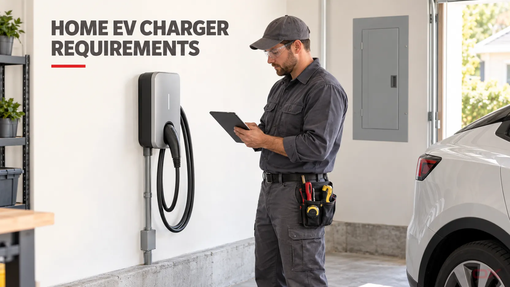
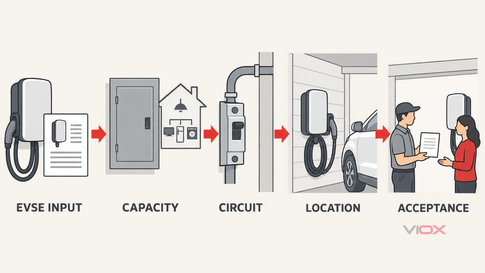
A safe Level 2 home electric vehicle supply equipment (EVSE) installation requires more than a 240 V outlet and an open breaker position. Before the charger is energized, five gates must be accepted:
- The EVSE model, connection method, and enforceable maximum current are defined.
- The service, feeder, panel, and dwelling load assessment support that current—or an approved energy-management method limits it.
- A dedicated branch circuit and its protection are designed for the actual installation.
- The listed equipment, mounting location, environment, and cable route are suitable.
- Settings, protective functions, charging operation, permit inspection, and homeowner handoff are documented.
An EVSE’s built-in protection does not prove that the upstream branch circuit is correct. Likewise, an empty panel space does not prove that the service has enough capacity. The final design must follow the adopted electrical code, the authority having jurisdiction (AHJ), the EVSE instructions, and the calculations for the specific dwelling.
This guide covers single-family North American residential Level 2 AC charging. It is a project-requirements and acceptance guide for homeowners, electrical contractors, reviewers, and equipment buyers—not a DIY wiring procedure.
The Five-Gate Acceptance Map
| Gate | Requirement to establish | Evidence to keep | Stop the project when |
|---|---|---|---|
| 1. EVSE definition | Exact model, supply connection, maximum input current, configured limit, indoor/outdoor use | Nameplate, instructions, certification record, configuration record | The equipment, current setting, or connection method is unknown |
| 2. Capacity | Service, feeder, panel, bus, and calculated or approved managed capacity | Load calculation or permitted load-management design; panel and service data | Capacity is inferred only from an empty breaker space |
| 3. Circuit and protection | Dedicated circuit, compatible overcurrent protection, conductors, terminals, grounding/bonding, and any required personnel protection | Circuit schedule, calculation, equipment compatibility, installation plan | Breaker, conductor, receptacle, or protection is selected by habit rather than evidence |
| 4. Equipment and location | Approved EVSE, suitable environment, mounting, cable reach, impact protection, and enclosure entries | Listing/certification details, site plan, equipment instructions | Weather, physical damage, cable routing, or approval status remains unresolved |
| 5. Acceptance | Verified settings, checks, charging session, load-management behavior, permit inspection, labels, and owner instructions | Commissioning sheet, inspection approval, photos, settings, manuals | A protective test fails, overheating appears, or final settings cannot be verified |
Start With a Project Input Sheet
The installation should be designed around the declared EVSE input—not merely its advertised kilowatt rating. Collect these inputs before requesting a final quotation:
- EVSE manufacturer and exact model;
- maximum input current and any lower configurable current settings;
- whether that current setting is installer-controlled, software-controlled, or physically locked;
- hardwired or cord-and-plug connection;
- supply voltage and phase stated in the instructions;
- vehicle onboard AC charging limit;
- indoor, outdoor, wet-location, or other environmental exposure;
- distance and proposed route from the service panel to the EVSE;
- normal parking position and required connector reach;
- dwelling service rating, panel rating, main breaker, existing large loads, and available panel positions;
- proposed load-management or energy-management system, if any;
- adopted code edition, permit process, utility requirements, and AHJ instructions.
The vehicle’s maximum AC charging rate and the EVSE’s maximum output are upper limits, not automatic design targets. A lower documented EVSE setting may meet the driver’s daily energy need while reducing the required circuit and service capacity. That setting must be controlled and accepted as part of the design; a homeowner-adjustable screen alone should not be assumed to provide an enforceable capacity limit.
For basic charger levels and AC-versus-DC terminology, first review the types of electric vehicle chargers. The remainder of this page assumes a fixed or fastened-in-place residential Level 2 AC EVSE.
Gate 1: Freeze the EVSE Configuration
The electrical design cannot be completed until the maximum load is defined. Record both the EVSE’s nameplate maximum and the commissioned maximum current. If the equipment supports several current settings, the project record should identify:
- who is authorized to change the setting;
- how the setting is secured against casual adjustment;
- whether loss of communications or a software reset can change the limit;
- whether the EVSE instructions permit the selected setting and connection method;
- whether the vehicle can request more current than the commissioned limit and how the EVSE enforces that limit.
This distinction matters when a service calculation or energy-management system depends on a reduced setting. A design based on 32 A is not complete if the installed unit can later return to 48 A without a controlled change process.
The U.S. Department of Energy (DOE) notes that EV charging equipment installations must comply with local and state requirements, may need permits, and fall principally under NEC Article 625 in NEC jurisdictions. The contractor must use the edition actually adopted locally rather than assuming that the newest national edition controls every project. See the DOE’s home charging guidance.
Gate 2: Prove Service and Panel Capacity
A spare two-pole position answers only one question: there may be physical room for a breaker. It does not establish adequate service, feeder, bus, meter, or transformer capacity.
A qualified electrical professional should establish at least:
- the service and main disconnect ratings;
- panel and bus ratings and any applicable loading limitations;
- feeder and service-conductor capacity;
- the existing dwelling demand under the adopted calculation method;
- the added EVSE load at its enforceable maximum setting;
- whether the panel accepts the proposed protective device;
- the condition of the panel, terminations, grounding, and bonding;
- whether the utility or AHJ requires notification, review, or an upgrade.
DOE identifies EV charging as a continuous load under the NEC and directs installers to the applicable provisions of Article 625. Exact circuit and service calculations must be made under the adopted code and local amendments. A current City of San José inspection example requires the panel rating, charging load, circuit size, and—under its stated conditions—a load calculation; that is useful evidence of what one AHJ expects, not a nationwide permit rule. See San José’s residential EV charging requirements.
If the dwelling has 100 A service or limited capacity, use the separate 100 A panel EV charger load-calculation and upgrade guide. It explains when a lower charging current, documented demand management, or a service upgrade may be appropriate.
When load management is part of the capacity solution
An EV energy-management system can reduce or suspend charging when dwelling demand approaches an approved limit. It should not be treated as a generic accessory. The design record needs to identify:
- the monitored conductors or measurement point;
- the service or feeder limit it protects;
- the EVSE current range it can command;
- its response when sensors, communications, or control power fail;
- whether the equipment and method are accepted under the adopted code;
- how its limiting function was verified during commissioning.
A timer that shifts charging to nighttime may reduce coincident demand in practice, but scheduling alone is not automatically an approved capacity-control method.
Gate 3: Define the Dedicated Branch Circuit and Protection Boundary
The branch circuit begins at the panel and ends at the EVSE supply connection. Its components must be treated as one coordinated path:
panel and bus → compatible protective device → conductors and raceway/cable → terminations or receptacle → EVSE → vehicle connector
The circuit design should document:
- EVSE maximum or enforceable configured current;
- branch-circuit and overcurrent-device rating under the adopted rules;
- conductor material, insulation, ampacity, routing, installation method, ambient conditions, grouping, and voltage-drop review;
- equipment terminal temperature and conductor-material limitations;
- breaker compatibility with the exact panel or switchboard;
- available fault current and adequate interrupting rating;
- equipment grounding and bonding path;
- personnel-protection and ground-fault functions provided by the EVSE and those required externally;
- disconnecting, locking, or servicing provisions required by the equipment and jurisdiction;
- surge-protection decision where required by the adopted code or project risk assessment.
Do not infer conductor size from breaker current alone, and do not assume that a breaker that physically fits a panel is approved for it. The detailed calculation belongs in the EV charger circuit-breaker sizing guide; the project electrician must still verify the adopted code and the exact equipment instructions.
Product protection and installation protection are different layers
North American residential EVSE is commonly evaluated under UL 2594 within that standard’s scope, while personnel-protection systems are addressed by the UL 2231 series. UL’s EV charging infrastructure standards overview lists those distinct equipment standards.
That product evaluation does not select the panel breaker, prove conductor ampacity, approve a receptacle, or settle every upstream ground-fault requirement. Conversely, adding an upstream protective device does not compensate for an unapproved EVSE. Product listing, manufacturer instructions, adopted installation code, and AHJ approval are separate but connected evidence layers.
ENERGY STAR advises homeowners to choose safety-certified equipment tested by a nationally recognized testing laboratory and to have a licensed electrician assess the home’s wiring, outlets, and related hardware. See the ENERGY STAR EV charger guidance.
Hardwired vs Receptacle-Supplied EVSE
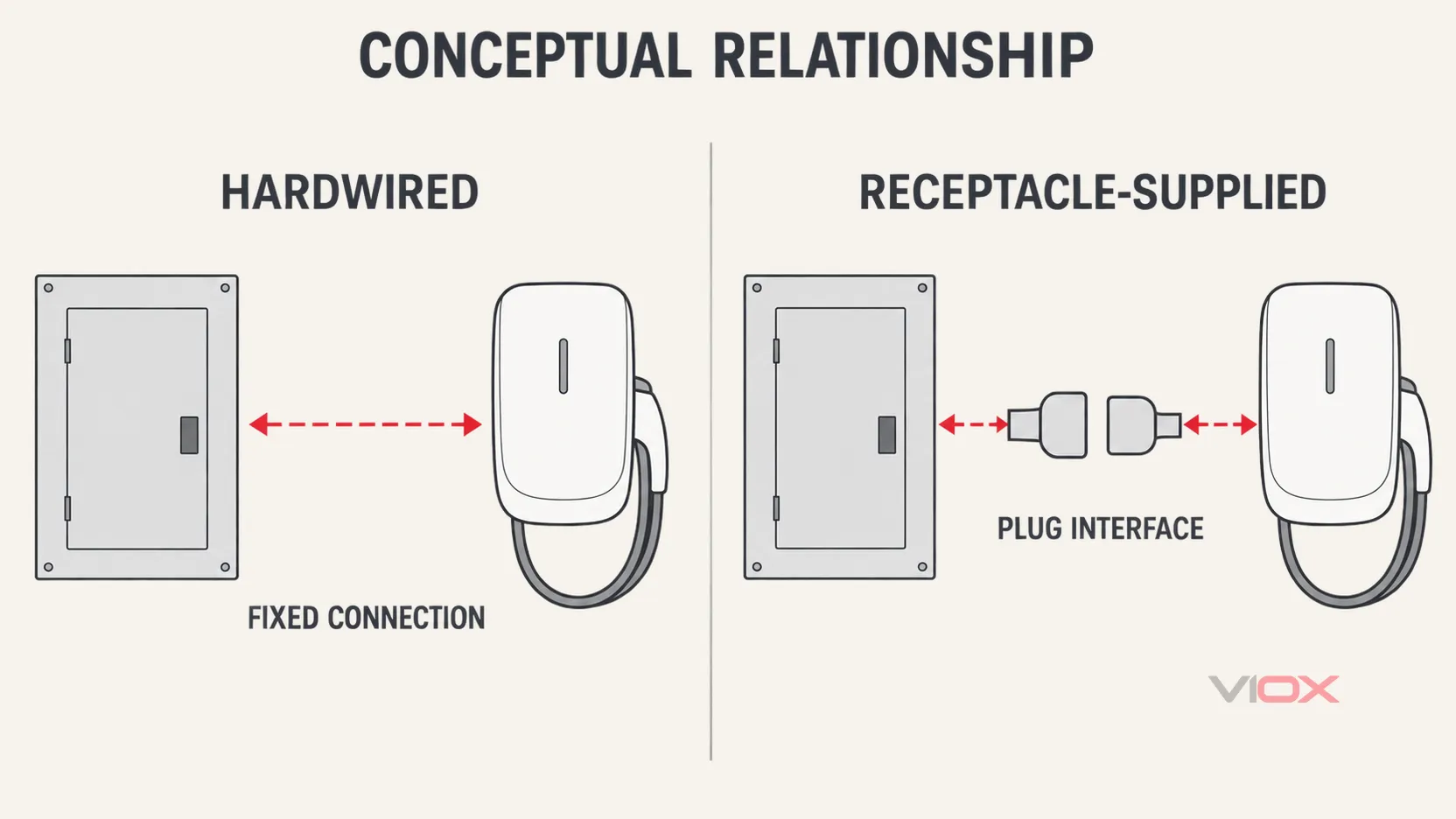
The connection method changes both the physical interfaces and the inspection evidence. It should be chosen before the circuit is quoted.
| Review point | Hardwired EVSE | Receptacle-supplied EVSE |
|---|---|---|
| Supply interface | Conductors terminate inside or at the EVSE according to its instructions | Branch circuit terminates at an approved receptacle; EVSE plug and cord remain additional interfaces |
| Main benefit | Fewer plug/receptacle contact interfaces; suitable for equipment that requires permanent connection | EVSE can be disconnected without opening its wiring compartment when the product and installation permit it |
| Evidence needed | Approved wiring method, conductor/terminal compatibility, entry sealing, strain relief, and disconnect/service provisions | Approved receptacle and enclosure, plug/receptacle rating and compatibility, mounting, conductor termination, ground-fault requirements, and product instructions |
| Common unresolved risk | Incorrect enclosure entry, termination, or field-configured current | Worn or poor-quality contact interface, incorrect receptacle/enclosure, unsupported adapter, or repeated unplugging duty |
| Code boundary | Follow the adopted code and exact EVSE instructions | Receptacle and GFCI requirements depend on the adopted code edition, location, rating, and AHJ interpretation |
Do not add an extension cord, multi-outlet adapter, travel adapter, or improvised conversion merely to make an incompatible installation reach. Use only the connection arrangement permitted by the EVSE, vehicle, adapter, and locally adopted requirements. If those documents do not establish compatibility, stop and obtain an approved design.
For IEC-oriented projects, residual-current device and direct-current leakage questions require a different standards pathway; use the separate EV charger RCD selection guide. Do not transfer an IEC device prescription into a North American installation without the applicable listing and code basis.
Gate 4: Approve the Equipment and Location
The charging location is part of the electrical design because the connector is handled frequently and the cable may cross an occupied parking area.
Equipment approval
Keep the listing or certification information, exact model instructions, configured rating, supply method, and environmental limitations with the project record. A marketplace listing that merely displays a certification logo is not the same as a verifiable certification record.
Indoor and outdoor exposure
DOE states that outdoor charging can be used safely when the equipment is rated for outdoor installation. The complete installed arrangement must also address enclosure entries, fittings, mounting surface, drainage, sunlight, water exposure, corrosion, temperature, and any locally applicable wet-location rules.
Mounting and physical damage
Position the EVSE so that:
- the vehicle can park normally without crushing the cable or connector;
- the connector reaches the inlet without tension;
- the cable does not create an avoidable trip path;
- the equipment and connector are not exposed to predictable vehicle impact;
- mounting clearances and height follow the instructions and accessibility requirements;
- the cable and connector have a defined storage position;
- the enclosure remains accessible for operation, inspection, and service;
- penetrations and fire-rated construction, where relevant, are restored under approved details.
Do not invent a universal mounting height, bollard spacing, or cable length. These depend on the product, parking geometry, accessibility rules, building construction, and local requirements.
Wi-Fi is operational, not protective
Network access may be needed for scheduling, utility programs, firmware, monitoring, or load management. A weak connection is an operational problem if the project depends on those functions. It must not be allowed to defeat an enforceable electrical limit; document the safe state for lost communications.
Gate 5: Commission, Inspect, and Hand Over
Commissioning demonstrates that the installed system matches the approved design. It is not limited to seeing the vehicle begin charging.
The qualified installer should record the checks required by the adopted code, AHJ, EVSE instructions, and test procedures. A useful acceptance record includes:
| Acceptance item | Record |
|---|---|
| Equipment identity | Manufacturer, model, serial number if applicable, listing/certification evidence |
| Electrical configuration | Supply, connection method, circuit identification, protective device, conductor information |
| EVSE setting | Nameplate maximum, commissioned maximum current, control/locking method |
| Installation checks | Mounting, enclosure entries, cable/connector storage, grounding/bonding, labels, required torque documentation |
| Functional checks | EVSE startup/self-test indications, fault-free charging handshake, one observed charging session |
| Protective checks | Tests required by the manufacturer, adopted code, AHJ, and approved test method |
| Managed charging | Sensor orientation, configured limit, current reduction or stop response, communications-loss behavior |
| Authority acceptance | Permit number, inspection result, utility approval when applicable |
| Handoff | Instructions, settings, warranty/certification records, reset procedure, service contact, change-control warning |
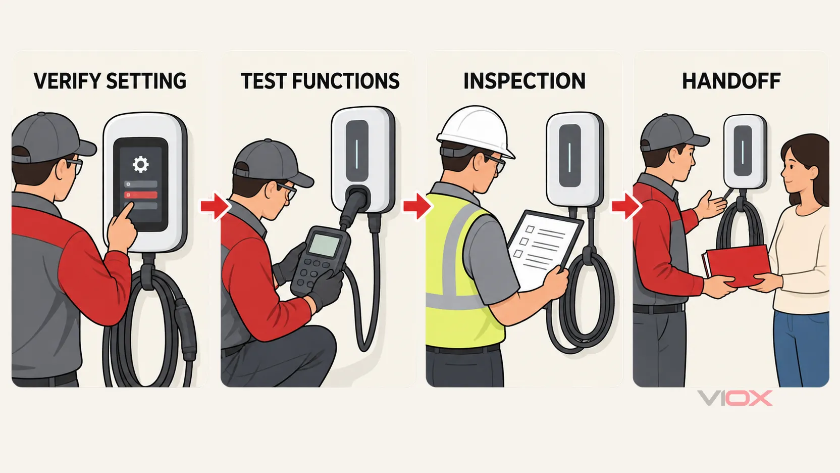
Do not publish generic torque values or test thresholds in place of the exact equipment instructions and approved test method. A failed self-test, abnormal fault indication, unstable current control, damaged connector, evidence of heating, or unsuccessful AHJ inspection is a stop condition—not an item to waive because charging appears to work.
What the homeowner should receive
The handoff package should show:
- which circuit supplies the EVSE;
- the commissioned maximum current and who may change it;
- how normal status and fault indications appear;
- how to use the connector and store the cable;
- which reset actions the manufacturer permits;
- what damage, looseness, discoloration, odor, heat, water entry, or repeated tripping requires the charger to be taken out of service;
- whom to contact for electrical or equipment service;
- the permit/inspection record, instructions, and relevant warranty or certification documents.
Any later change to EVSE current, breaker, receptacle, circuit routing, service capacity, load-management equipment, or charger model should trigger a design review rather than being treated as a software preference.
Stop Conditions: Do Not Energize Yet
Stop the project and obtain qualified review when any of these remain unresolved:
- the EVSE model, maximum current, or connection method is unknown;
- the service assessment is replaced by the assumption that an empty breaker space means spare capacity;
- the panel is damaged, obsolete, contaminated, incorrectly modified, or cannot be matched to an approved protective device;
- aluminum/copper conductor compatibility, terminal ratings, or existing conductor condition is uncertain;
- the proposed conductor route, burial, raceway, wall penetration, or outdoor entry lacks an approved method;
- the EVSE approval mark or certification record cannot be verified;
- a plug, receptacle, extension, or adapter combination is not explicitly supported;
- environmental rating, water exposure, impact risk, or cable management is unresolved;
- an energy-management limit is not enforceable or its failure behavior is unknown;
- a protective or functional test fails;
- there is abnormal heating, discoloration, odor, damaged insulation, repeated tripping, or water entry;
- permit, inspection, utility, landlord, or property-approval requirements are incomplete.
Home EV Charger Installation Checklist
Use this as a handoff checklist, not as permission to perform electrical work without the qualifications required locally.
Before equipment selection
Before circuit design approval
Before energization
At homeowner handoff
Once the design inputs are verified, a protection proposal may route to appropriate VIOX MCB, RCBO, or SPD families. Product selection must still match the target market, exact ratings, panel or assembly compatibility, manufacturer documentation, and approved project design.
Technical Sources
- U.S. Department of Energy Alternative Fuels Data Center — Charging Electric Vehicles at Home
- U.S. Department of Energy Alternative Fuels Data Center — Electric Vehicle Readiness
- UL Solutions — Electric Vehicle Charging Infrastructure Services
- ENERGY STAR — Electric Vehicle Chargers
- City of San José — Residential Electric Vehicle Charging Stations
Only qualified personnel should design, install, test, alter, and maintain residential EV charging circuits. Final work must follow the adopted electrical code, AHJ and utility requirements, the approved project documents, and the current instructions for the exact equipment installed.