

On this page
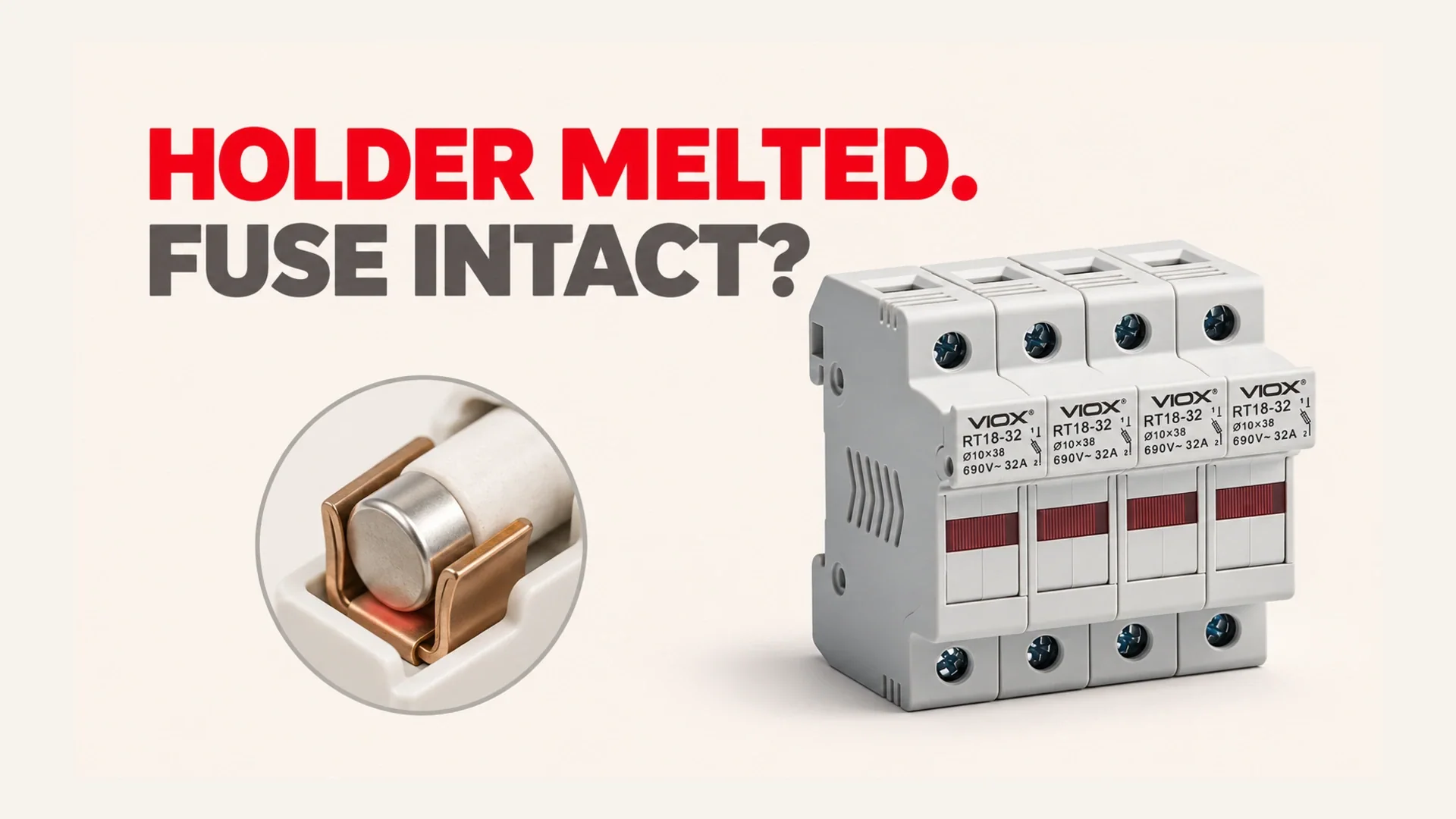
A fuse holder can melt because a poor electrical contact generates concentrated heat while the fuse element remains intact. Current crossing a loose, oxidized, or damaged fuse-cap-to-clip interface produces local I-squared-R heating, even when the current is within the fuse’s normal operating range. The fuse protects against overcurrent according to its time-current characteristic; it is not a temperature sensor for its mounting contacts. As heat weakens contact pressure and worsens the interface, resistance can increase further, so the damage becomes self-reinforcing. An intact fuse therefore does not prove the connection is safe, or that current has never exceeded the fuse rating.
The Mechanism: Contact Resistance Concentrates the Heat
Current must cross the physical contact between the fuse end cap and its retaining clip. Those apparently broad metal surfaces touch through much smaller real contact areas. Adequate pressure, correct fit, and sound surfaces keep that interface conductive; weak pressure or contamination can increase its resistance.
The relationship is:
P_contact = I^2 x R_contact
Here, P is electrical loss converted to heat at the connection, I is current, and R is that connection’s resistance. For AC heating assessment, use the appropriate RMS current. The important diagnostic point is that resistance can increase while load current stays unchanged. Littelfuse’s Fuseholder Selection Guide identifies clip contact resistance as a heat source and explains why actual enclosure and connection conditions matter.
The fuse element has its own heating and cooling balance. Heat transferred from a bad connection may eventually affect it, but the fuse cannot be relied upon to open before the nearby holder is damaged. A resistive connection can therefore destroy its support without creating the overcurrent needed for prompt fuse operation. OptiFuse explains this separation between holder heating and fuse protection.
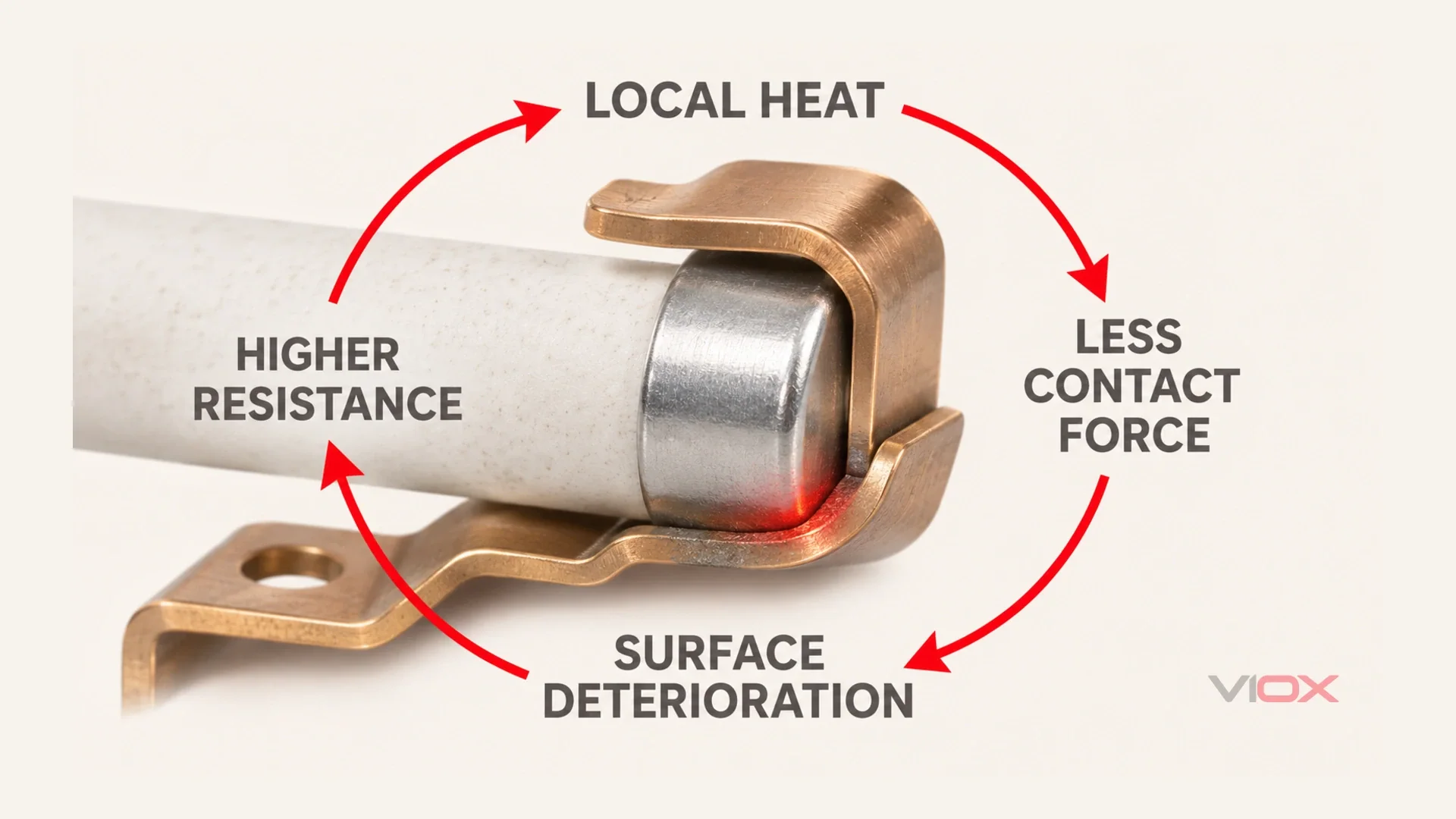
The Heat-Feedback Loop
The common failure is progressive, not necessarily present at full severity on installation day.
| Stage | What changes | Why the next stage becomes more likely |
|---|---|---|
| Local contact heating | Heat concentrates at a clip, cap, or termination | The contact system experiences greater thermal stress |
| Contact-force loss | Springs can relax; severe overheating can anneal susceptible material | Less effective pressure reduces reliable metal contact |
| Surface deterioration | Oxidation, corrosion, or damaged plating impairs the interface | Contact resistance can increase |
| Further heating | The same current crosses the poorer connection | Housing distortion, melting, or carbonization can follow |
Mersen’s clip-clamp documentation specifically connects contact pressure, resistance, overheating, and loss of spring tension through annealing. Not every relaxed spring has been proven annealed, and a functioning assembly can reach thermal equilibrium. The dangerous loop develops when deterioration keeps reducing the connection’s margin.
This explains both delayed failure and repeat failure. A new installation may initially conduct adequately, then deteriorate through heat, vibration, contamination, and thermal cycling. Replacing only the fuse leaves the same weakened clip, damaged terminal, or distorted support in place, so the next fuse inherits the same problem.
Where the Loop Starts
Insufficient or declining clip tension: A poorly matched fuse, bent clip, worn carrier, or spring that loses force can reduce contact quality. Firm retention must be achieved by the intended design, not improvised bending.
Oxidation or contamination: Corrosion, dirt, moisture-related deposits, and damaged plating can interfere with contact. Abrading a plated surface can remove the protection it needs; cleaning must follow the holder manufacturer’s instructions.
Poor bolt preload or support: In bolted holders, an incorrect terminal stack or insufficient tightening can leave a resistive joint. If the connection’s clamp load is improperly carried through plastic, deformation can reduce preload. Use the specified hardware stack and supported load path rather than adding arbitrary washers or torque.
Insufficient thermal capability: A holder or enclosure arrangement may be unsuitable for the actual continuous load and surrounding temperature. The fuse’s current marking does not establish the holder’s thermal margin.
Unverified contact and spring construction: Price alone is not a diagnosis. Inspectable differences include contact geometry, plating condition, separate spring support, alignment, and whether clamping force depends on a deformable support. Ask for documented performance instead of assuming a low-cost or premium label proves quality.
Where It Shows Up
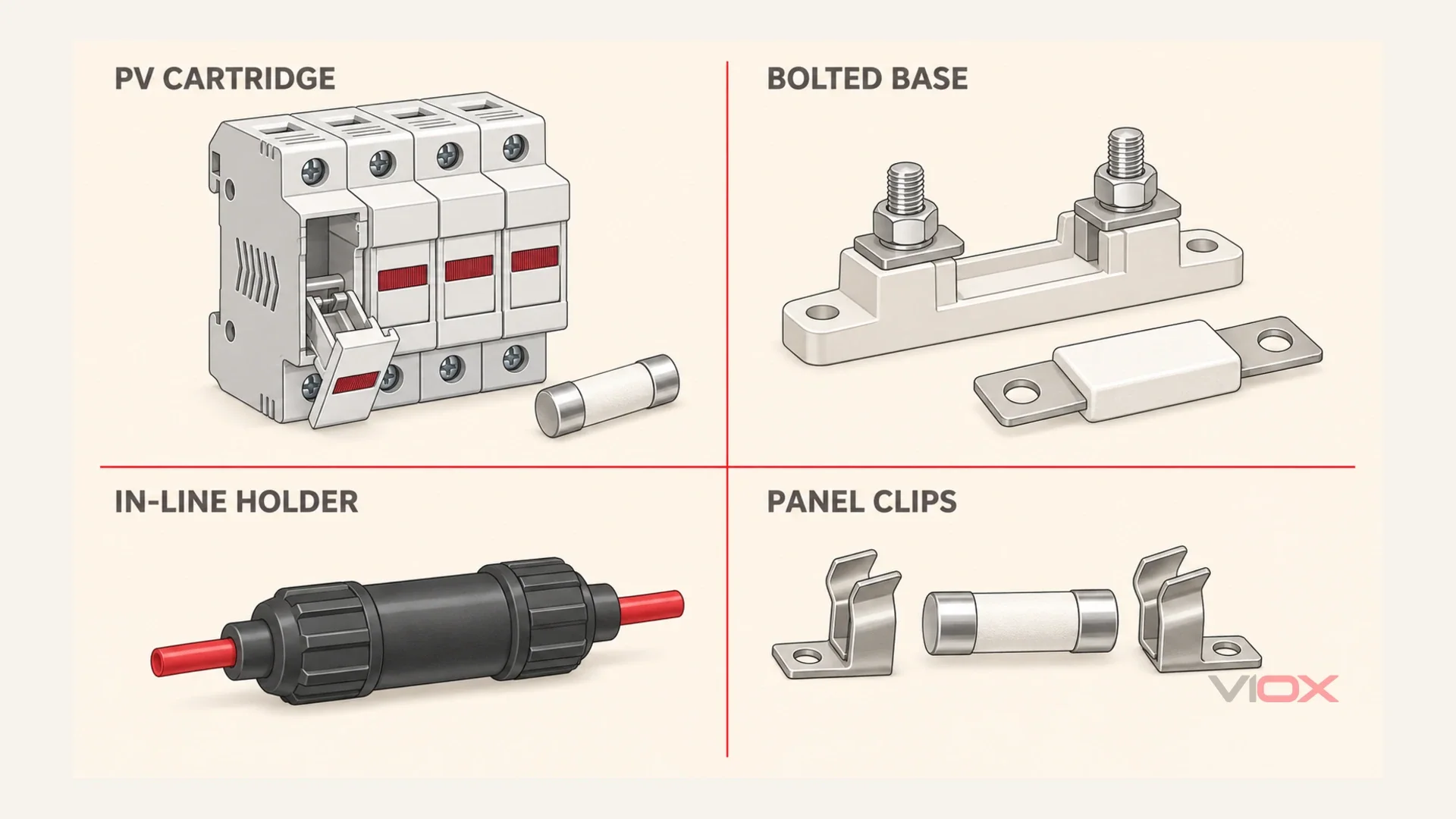
PV 10 x 38 mm Fuse Holders
In a photovoltaic combiner, damage may concentrate around one cartridge end or one holder while neighboring positions look normal. Compare equivalent positions carefully: different string currents or shade can change heating. A hot enclosure can aggravate the local defect, but it does not explain every isolated damaged contact.
Ambient derating reduces permissible operating current as surrounding temperature rises; this article diagnoses localized connection heating. These are different mechanisms that can coexist. For the former, use the PV combiner temperature-derating guide.
Bolted Battery Main-Fuse Holders
Look for damage around a stud, fuse tab, lug, or insulating support rather than assuming the fuse element caused it. A loose stack, incompatible lug, cable strain, or heat-damaged support can compromise the joint. Heating can extend into the conductor and insulation, making a fuse-only replacement incomplete.
12V In-Line Holders
A softened cap, discolored wire entry, intermittent load, or load-side voltage sag can indicate a weak internal contact or crimp. Check the termination as well as the fuse grip. Eaton’s in-line crimping guidance explains how a loose crimp raises resistance and temperature under load. This is a connection diagnosis; fuse sizing belongs in the 12V fuse-size guide.
Distribution-Panel Fuse Clips
One clip may show heat discoloration, oxidation, or loss of retention even though the fuse still passes continuity. The upstream conductor termination can also be the heat source. Inspect the connected path instead of condemning a clip from color alone. Eaton Bussmann’s maintenance guidance addresses discoloration, contact pressure, infrared examination, and manufacturer-specified tightening.
Signs to Look For
Housing yellowing or browning, distorted plastic, a deformed carrier, carbonized insulation, or a burnt smell requires investigation. Stop using an assembly with obvious heat damage; do not wait for the fuse to open.
Fuse end-cap discoloration, corrosion, or an altered surface can locate the affected interface, but appearance does not establish the complete cause. Check both ends and the adjoining terminals. A contact problem may start outside the holder and conduct heat into it.
Other useful clues are load-side voltage falling when the load operates and repeated heating at the same position after replacement. Neither clue provides a universal failure threshold. Record the load state, affected location, fuse identity, and comparison conditions so a technician can connect the evidence rather than rely on touch or memory.
How to Confirm It
Inspection and replacement default to de-energized work, isolation, and verification of absence of voltage under the applicable site procedure. Never twist, remove, or reseat a fuse under load as a diagnostic experiment.
PV warning: PV source circuits can remain energized in daylight despite downstream switching. Have qualified personnel handle the condition under the site’s procedures; this guide provides no live PV work sequence.
Battery warning: A main battery-fuse circuit can release extremely high short-circuit energy. Have qualified personnel handle it under the site’s procedures. Low nominal voltage does not remove that hazard.
Compare Loaded Voltage Drop
A qualified technician can evaluate existing records or perform a justified loaded voltage-drop assessment under an approved procedure. Millivolt-scale loss across the holder assembly can reveal an impaired path when compared with the manufacturer’s data or a healthy equivalent position.
Define the measurement span. A reading across the complete installed assembly includes the fuse element and multiple connections, not just one clip. Compare the same fuse type, similar current and operating conditions, and consistent endpoints. Otherwise a difference may be normal fuse loss or a different test setup.
An excessive drop relative to valid reference conditions supports further localization of the resistive joint. It is not enough to declare “above this many millivolts is bad.” A no-load reading also cannot clear a connection that deteriorates under load. Do not re-energize a visibly melted assembly merely to obtain a measurement.
Check Grip Only Where the Design Permits
With power isolated and absence of voltage verified, assess seating and retention by the manufacturer’s method. On an accessible round-cartridge clip arrangement, a fuse that spins freely with almost no grip, compared with the correct known-good arrangement, is a warning of poor fit or retention.
Rotation alone is not a universal rejection test: some round cartridges can rotate while still having adequate contact pressure, and enclosed carriers may not permit this check. Do not force rotation, reach into inaccessible contacts, or substitute hand feel for specified retention evidence.
Compare Infrared Patterns
Infrared inspection can help distinguish a localized end-contact hot spot from general enclosure heating. Compare equivalent positions at comparable loads, allowing for reflective surfaces, emissivity, viewing access, and the camera’s limitations. Safe access and any energized examination belong to qualified personnel under site rules.
A surface image does not directly measure a hidden interface. Combine its pattern with inspection and electrical evidence; never use a universal temperature difference to approve a damaged holder.
Why the Usual Fixes Fail
Fitting a Bigger Fuse
A larger fuse does not restore contact pressure or remove oxidation. At the same load current, the defective interface still generates heat. Raising the fuse rating may also let excessive current persist longer, weakening the intended conductor or equipment protection. Keep the required fuse specification while repairing the connection.
Replacing Only the Fuse
A fresh fuse placed into weakened clips or a distorted carrier can overheat again. Its new end cap does not repair a damaged contact surface. For an assembly that has melted, replace the holder and fuse as a matched repair, and examine the adjoining wiring. An intact element does not prove its caps or body escaped thermal damage.
Squeezing the Clips With Pliers
Bending a clip may temporarily increase apparent grip without restoring the spring’s material properties or intended geometry. It can damage plating or alignment and conceal continued deterioration. Do not treat this as an approved emergency repair. Replace damaged hardware; use a manufacturer-approved service component only where the exact system permits it. Purpose-designed accessories are not equivalent to improvised squeezing.
The Correct Fix
Remove the damaged holder from service and replace it together with the correct fuse. Select a matched assembly rather than reusing a heat-exposed link because it still tests continuous. Confirm that the original fuse specification remains appropriate; if the element itself repeatedly opens, that is the separate fuse-keeps-blowing diagnosis.
Trace heat damage into the wiring. Remove affected terminals and cut back or replace heat-damaged cable until sound conductor and insulation are reached, using the approved repair method. Do not simply wrap brittle insulation or cut insulation away and leave exposed conductor. If adequate sound cable length remains unavailable, replace the run.
For bolted joints, restore the specified lug, washer, support, and clamp arrangement. Apply only the torque documented for that holder and connection, using the required method and tool. A value copied from another fuse base can overload plastic supports or leave the joint loose.
Before return to service, identify what allowed the problem: loss of grip, contaminated surfaces, unsuitable hardware, cable strain, incorrect crimping, or inadequate thermal conditions. After safe restoration checks, confirm loaded voltage drop against the valid reference and compare thermal behavior under representative operation. Document the fuse, load, measurement span, repaired components, and result. If the same position remains abnormal, stop and continue diagnosis rather than accepting another fuse replacement.
Choosing a Holder That Does Not Do This
Prevent recurrence by asking how contact force is maintained, what contact material and plating are specified, whether the fuse fits the intended interface, and what supports the mechanical clamping load. Check the housing’s documented thermal capability and operating margin in the actual enclosure. A material name or current marking alone is insufficient evidence.
Keep the detailed product decision with the Complete Guide to Fuse Holders and How Does a Fuse Holder Work. This diagnosis does not replace their compatibility and selection checks.
For VIOX products, the RT18 holder page identifies a DIN-rail cartridge-holder arrangement with a removable fuse-installation interface. VIOX also identifies VOPV-32 as a DIN-rail PV fuse holder in its combiner product documentation. Ask for the exact holder’s contact design, installation instructions, and thermal evidence before specifying a replacement; these listings do not establish immunity to contact heating.
FAQ
Why did my fuse holder melt but the fuse is still good?
A resistive connection can overheat locally without the fuse element reaching its opening condition. The holder may be failing even though the element is continuous. Confirm the connection and thermal conditions rather than assuming the fuse is defective.
Can a loose fuse cause a fire?
Yes. Poor contact can generate concentrated heat and may arc, damaging insulation and potentially igniting nearby material. Stop using a loose or heat-damaged assembly and arrange qualified inspection. Do not rely on the fuse to clear every connection fault.
Should I replace the fuse or the holder?
For a melted assembly, replace both as a matched repair and inspect the wires and terminals. Heat can compromise the holder’s force, surfaces, or support and damage the fuse end caps. Reusing either part can transfer the fault to the replacement.
Is it normal for a fuse holder to feel warm?
Some heating occurs in normal service, but touch cannot establish whether operation is acceptable. Use the manufacturer’s limits and valid comparative evidence. Discoloration, deformation, smell, or progressive heating must not be dismissed as normal warmth.
Will a bigger fuse stop the holder from melting?
No. It does not repair the resistive interface and can reduce protection for the circuit. Replace the damaged matched components, correct the cause, and retain the appropriate fuse specification.