On this page
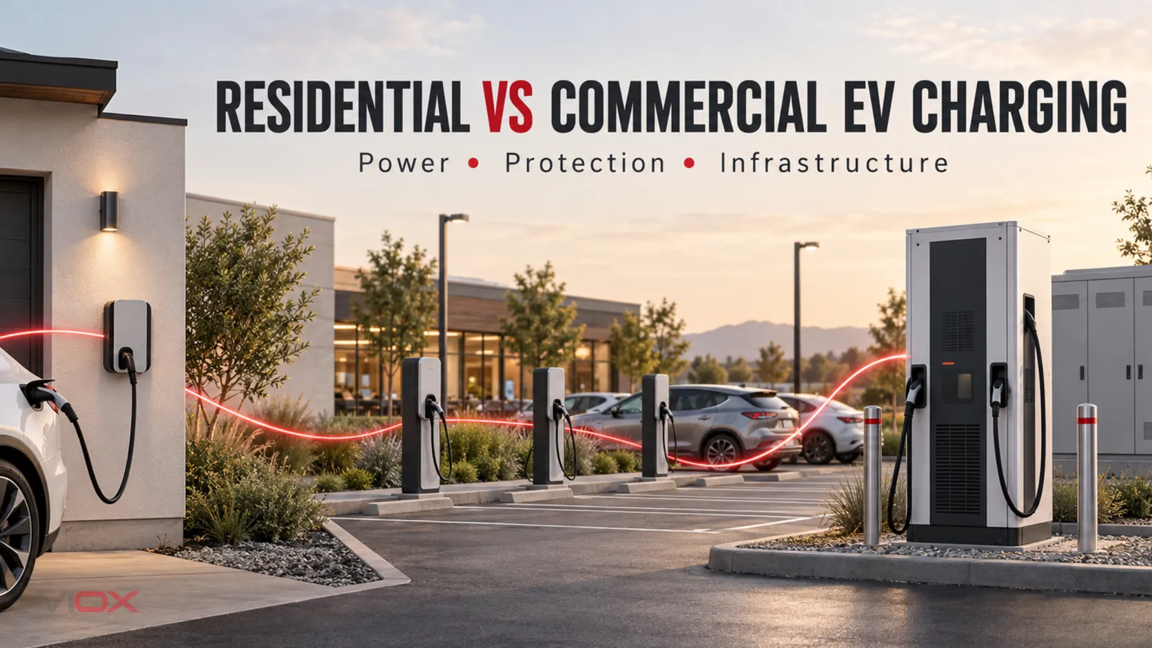
Residential versus commercial charging is not the same distinction as AC versus DC charging. Most residential installations use AC electric vehicle supply equipment (EVSE). Public sites may use AC destination chargers, high-power DC chargers, or both.
Commercial and public are not exact synonyms. A private fleet depot can be commercial without public access, while a curbside charging point may be publicly accessible. In this guide, the public AC and public DC columns represent the multi-user infrastructure patterns commonly encountered in commercial and publicly accessible projects; the actual access model remains a separate design input.
The correct design sequence is:
- Identify whether the vehicle receives AC or DC.
- Classify the site by access, utilization, outlet count, availability, and expansion needs.
- Verify supply capacity, prospective fault current, earthing, certified EVSE functions, local installation rules, and manufacturer instructions.
A site label such as home, workplace, or public does not select the breaker, residual-current device, surge protective device, conductor, or disconnect.
Residential AC vs Public AC vs Public DC
| Design question | Residential AC | Commercial/public AC | Commercial/public DC fast charging |
|---|---|---|---|
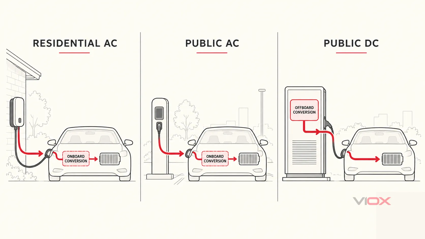
| Power delivered to the vehicle | AC; the onboard charger converts it to DC | AC; the onboard charger converts it to DC | DC; conversion occurs in off-board charging equipment |
| Typical context | Private driveway, garage, or assigned residential space | Workplace, hotel, retail, fleet, car park, or curbside charging | Highway corridor, fleet depot, charging hub, or rapid-turnover site |
| Operating duty | Usually one household with predictable dwell time | Multiple users, longer operating hours, and variable occupancy | High power, shorter sessions, and demanding equipment duty |
| Main distribution challenge | Available service and dwelling demand | Aggregated demand, outlet count, diversity, access, and expansion | Utility capacity, transformer and switchgear duty, conversion losses, cooling, and uptime |
| Protection boundary | Dedicated final circuit plus verified EVSE functions | Per-connection-point protection coordinated with the charging distribution system | Upstream AC protection coordinated with the charger’s certified internal AC/DC architecture |
| Management requirement | Scheduling or home energy management may be sufficient | Dynamic allocation, authorization, metering, and remote monitoring may be required | Power sharing, demand control, uptime monitoring, and planned maintenance are central |
| Evidence package | Load calculation, final-circuit design, EVSE instructions, certification/listing, and local approval | Site load study, outlet schedule, EVSE documentation, communications and maintenance plans | Utility study, single-line diagram, fault and coordination studies, charger certification, commissioning, and service plan |
This table classifies the engineering task; it is not a device-selection schedule. Two projects in the same column can require different conductors, breakers, residual-current protection, surge protection, and distribution equipment.
Why Site Type Alone Does Not Define the Electrical Architecture
A residential charger and a public AC charge point can share the same broad power path: the site supplies AC and the vehicle’s onboard charger converts it to battery DC. Their utilization and infrastructure duties can nevertheless differ substantially.
A public AC site may need user authorization, revenue metering, network communications, remote resets, load allocation, and documented maintenance access. A single residential charge point may need none of those functions, yet it still requires a properly designed final circuit and a residual-current strategy compatible with the EVSE.
Public DC charging creates a different equipment boundary. The charger performs off-board conversion and may contain power modules, cooling, switching, insulation monitoring, output controls, and DC protective functions within its certified construction. The site designer must coordinate the upstream AC system with that equipment rather than scale up an AC wallbox circuit.
For connector families, charging modes, and basic terminology, use the Types of Electric Vehicle Chargers guide as orientation. The present page owns the infrastructure comparison, not the connector taxonomy.
Residential AC Charging: Start With Available Capacity
In a typical residential AC installation, fixed EVSE controls the vehicle connection while the onboard charger converts AC to DC. The EVSE is normally supplied from a dedicated final circuit in the residential distribution board.
The design begins with the dwelling, not the charger headline power. Verify:
- service and distribution-board capacity;
- existing maximum demand and any approved demand-control method;
- EVSE maximum input current and manufacturer-specified upstream requirements;
- conductor ampacity, installation method, grouping, ambient conditions, voltage drop, and terminal limits;
- prospective short-circuit current and protective-device breaking capacity;
- earthing arrangement and fault-disconnection conditions;
- integral EVSE protective functions and any external protection required by the adopted rules;
- operation and failure behavior of static or dynamic load management.
Scheduled charging can move demand to another time, but a timer alone does not prove adequate supply capacity. If an energy-management system controls charging current, document its measurement point, enforceable limit, response behavior, communication-loss state, and commissioning test.
Detailed 7 kW and 22 kW circuit calculations belong in the EV Charger Circuit Breaker Sizing Guide. Do not copy a breaker size from another installation without checking the actual supply, conductor, ambient conditions, fault level, EVSE instructions, and local code.
Public AC Charging: Design the Final Circuits and the Aggregate System
Public AC destination charging retains the AC-to-onboard-charger power path, but its site duty is different. Several vehicles may be connected simultaneously, operating hours are longer, and one distribution system may serve many charging points.
The project therefore has two linked design levels:
- Individual connection point: final-circuit overcurrent protection, residual-current strategy, isolation and switching functions, cable route, and EVSE requirements.
- Charging distribution system: feeder and busbar capacity, diversified demand, fault level, selectivity, metering, communications, environmental exposure, maintenance, and expansion.
Load management may allocate a fixed site capacity among connected vehicles. It does not erase final-circuit ratings or permit an undocumented overload condition. Define the maximum site allocation, minimum and maximum charger allocation, communications-loss behavior, manual override, and the method used to verify the limit during commissioning.
Public AC sites also need an operational failure strategy. If the network or controller fails, the specification should state whether charging stops, continues at a documented safe limit, or enters another manufacturer-approved state.
Public DC Charging: Coordinate With Certified Charger Architecture
DC fast charging moves AC-to-DC conversion outside the vehicle. A charger may combine rectification, power conversion, DC output control, cooling, monitoring, communications, and protective functions in a cabinet or modular power system.
Typical project inputs include:
- utility service and transformer capacity;
- main-board and feeder fault-current calculations;
- switchgear short-circuit ratings and documented coordination;
- charger maximum input, power factor, efficiency, harmonic, and fault data;
- feeder and cable thermal limits;
- power-module and charging-cable cooling requirements;
- manufacturer-defined emergency control, isolation, and maintenance boundaries;
- commissioning procedures, diagnostic access, spares, and qualified service support.
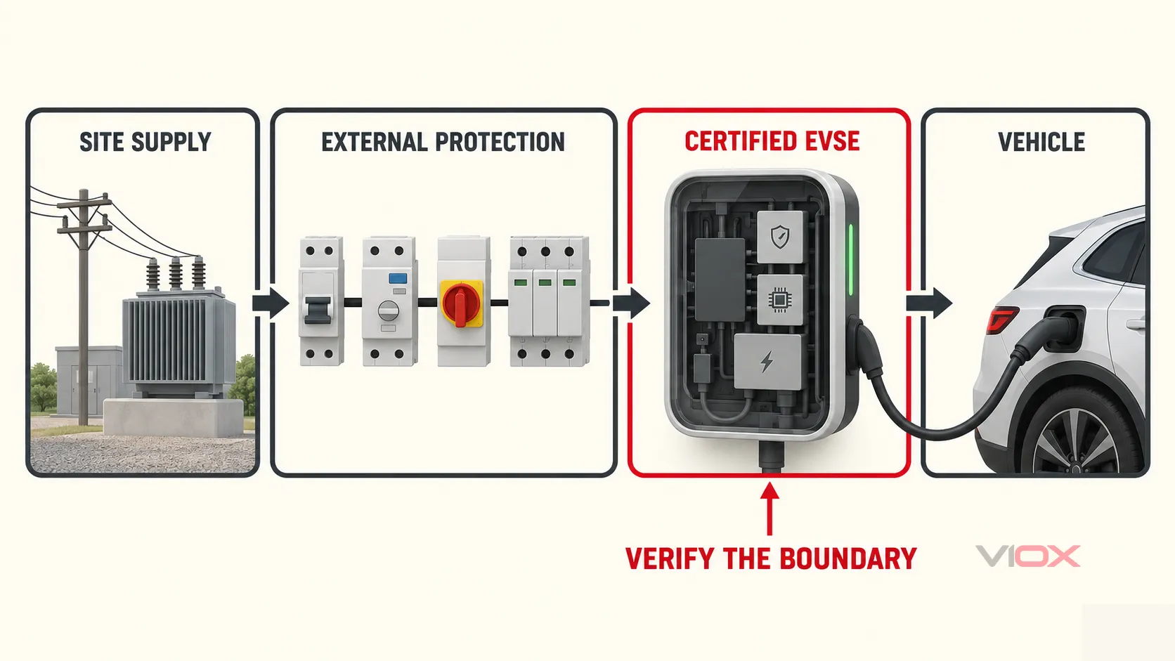
The charger manufacturer defines the certified internal DC protection and control architecture. The site designer remains responsible for the upstream AC supply, external switching and protection, installation environment, and coordination required by the equipment instructions and local rules.
Large commercial projects should continue with the Commercial EV Charging Protection Architecture guide, which maps ACB, MCCB, MCB/RCBO, RCD/RDC-DD, SPD, isolation, and control duties across the distribution hierarchy.
How the Protection Boundary Changes
Protection should be specified by function and evidence, not by assuming that every residential project uses one device type and every public project uses another.
Overcurrent and short-circuit protection
The protective device must suit the conductor, declared load, installation method, prospective fault current, required coordination, and EVSE instructions. Device family alone does not establish suitability. One project may use an MCB or RCBO on a final circuit; another may require an MCCB or a different assembly because of current, fault level, adjustability, selectivity, or distribution architecture.
Residual-current and DC residual-current detection
AC charging can produce residual-current conditions that affect the protection strategy. The external device depends partly on the protective functions incorporated in the EVSE.
IEC 62955:2018 covers residual direct-current detecting devices (RDC-DDs) for permanently connected Mode 3 AC charging stations within its stated voltage, current, and frequency scope. This does not prescribe one external RCD type for every installation. Verify the EVSE documentation, earthing system, adopted installation rules, and coordination between incorporated DC detection and upstream residual-current protection.
Use the EV Charger RCD Selection Guide for the detailed Type A, Type F, Type B, and RDC-DD decision. Commissioning personnel should follow approved procedures and exact equipment instructions rather than infer a test method from the words “6 mA DC”; see the separate RDC-DD verification guide.
Isolation, switching, and emergency control
The required means of isolation, functional switching, and emergency control depends on the architecture, equipment construction, location, utilization category, and locally adopted rules. The word public does not establish a universal external-disconnect location.
The single-line diagram should identify which means isolates each connection point, feeder, distribution section, and charger power module where applicable. Verify pole configuration, AC or DC rating, lockable state, access, and manufacturer-defined maintenance boundaries.
Surge protection
Surge protection depends on the installation’s supply arrangement, lightning-protection context, exposure, equipment withstand, upstream SPD stages, cable routing, and adopted rules. A charger is not assigned a Type 1 or Type 2 SPD solely because it is residential or public.
The EV Charger Surge Protection Guide covers SPD type, placement, coordination, backup protection, conductor routing, and status monitoring without relying on an arbitrary cable-distance rule.
Load management
Load management is a design function, not merely a software feature:
- Residential AC: keep total dwelling demand within the approved service limit.
- Public AC: allocate site capacity among several connection points while preserving documented circuit limits.
- Public DC: coordinate high-power chargers, power modules, storage, and other large loads against utility or transformer constraints.
Document the measurement point, response time, allocation limits, communications-loss state, manual override, and commissioning evidence. State whether the system is used only for optimization or forms part of the approved capacity-control method.
Standards and Acceptance Map
An equipment certificate does not approve the complete installation. Standards apply to different layers of the project.
| Project layer | IEC-oriented reference | North American reference |
|---|---|---|
| EV supply-circuit installation | IEC 60364-7-722:2018 plus nationally adopted wiring rules | Adopted electrical code, applicable EV charging provisions, and authority having jurisdiction requirements |
| General conductive EVSE | IEC 61851-1:2017, including the published 2023 corrigendum | UL 2594 for EVSE within its scope |
| DC charging equipment | Applicable IEC 61851 parts for the equipment and charging system | UL 2202 |
| Personnel-protection system | Installation rules plus declared certified equipment functions | UL 2231 series within the applicable EVSE system |
| Mode 3 DC residual-current detection | IEC 62955 within its stated scope | Verify the listed EVSE system and adopted code requirements |
UL Solutions’ EV charging infrastructure overview identifies the distinct roles of UL 2594, UL 2202, and the UL 2231 series. The applicable editions, national deviations, equipment listing or certification, installation instructions, and local acceptance path must be confirmed for the project jurisdiction.
Project Specification Checklist
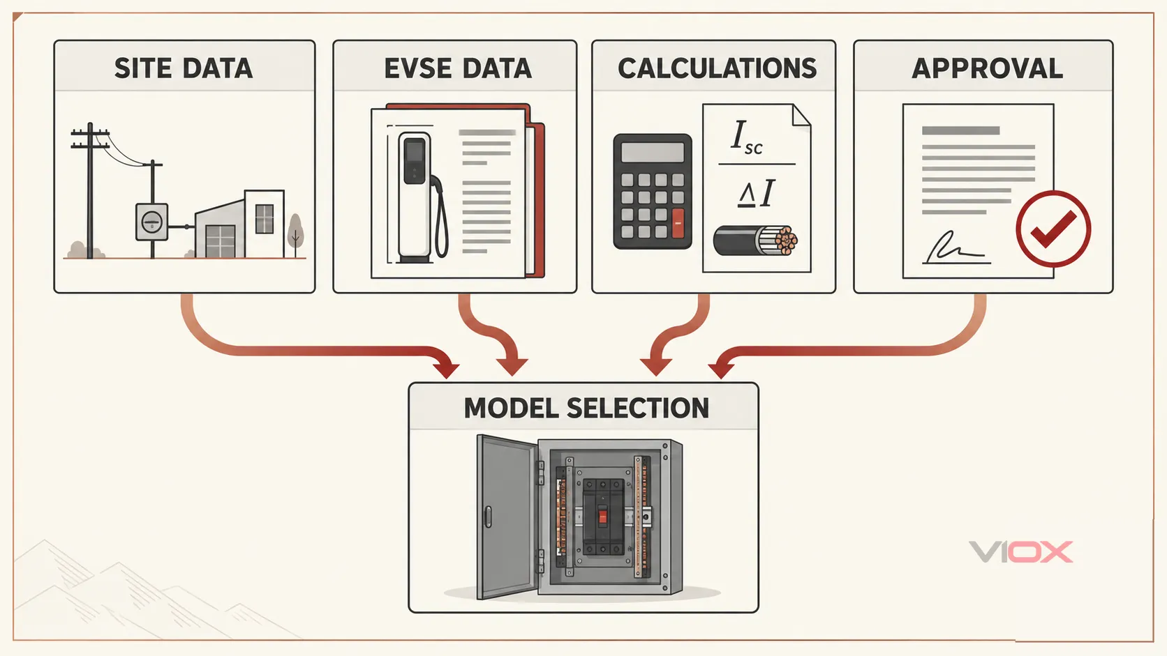
Before selecting breakers, RCDs, disconnects, or SPDs, collect this information:
| Input group | Required project information |
|---|---|
| Power path | AC or DC delivered to the vehicle; onboard or off-board conversion boundary |
| Site duty | Private residence, shared residential, workplace, public destination, fleet, depot, or fast-charging hub |
| Supply | Voltage, phases, frequency, earthing arrangement, available capacity, and prospective fault current |
| EVSE | Maximum input current, operating modes, incorporated protection, short-circuit data, certification/listing, and manufacturer instructions |
| Utilization | Connection-point count, expected simultaneity, dwell time, availability target, and expansion plan |
| Conductors | Material, route, installation method, ampacity, grouping, ambient conditions, voltage drop, and terminal limits |
| Protection | Overcurrent, residual current, isolation, surge, emergency control, and coordination requirements |
| Controls | Load-management method, measurement point, enforceable limit, communications-loss state, and commissioning test |
| Environment | Indoor/outdoor exposure, temperature, water, dust, corrosion, impact, accessibility, and maintenance space |
| Evidence | Adopted rules, authority decisions, certificates, instructions, single-line diagram, calculations, settings, and test records |
If these inputs are incomplete, selecting a protective device from charger power or site type alone is premature.
Preparing a Protection Proposal
For a model-level VIOX proposal, provide the supply voltage and phases, earthing arrangement, EVSE input data, connection-point schedule, calculated prospective fault current, conductor information, load-management method, destination market, single-line concept, and required certification documents. Depending on the calculated duties, the project may route to VIOX MCBs, MCCBs, RCBOs, or SPDs.
A supplier proposal does not replace the project designer’s calculations, the EVSE manufacturer’s instructions, tested device-coordination evidence, or approval by the responsible authority. For a documented review, contact [email protected] with the project input package above.
Technical Sources
- IEC 60364-7-722:2018 — Low-voltage electrical installations: supplies for electric vehicles
- IEC 61851-1:2017 — Electric vehicle conductive charging system: general requirements
- IEC 61851-1:2017/COR1:2023 — Corrigendum 1
- IEC 62955:2018 — RDC-DD for Mode 3 EV charging
- UL Solutions — Electric Vehicle Charging Infrastructure Services
- U.S. Department of Energy Alternative Fuels Data Center — Charging Electric Vehicles at Home
- U.S. Environmental Protection Agency — Plug-in Electric Vehicle Charging Basics
Only qualified personnel should design, install, test, and maintain EV charging electrical systems. Final equipment selection and installation must follow the locally adopted rules, authority requirements, project calculations, and current manufacturer instructions.