On this page
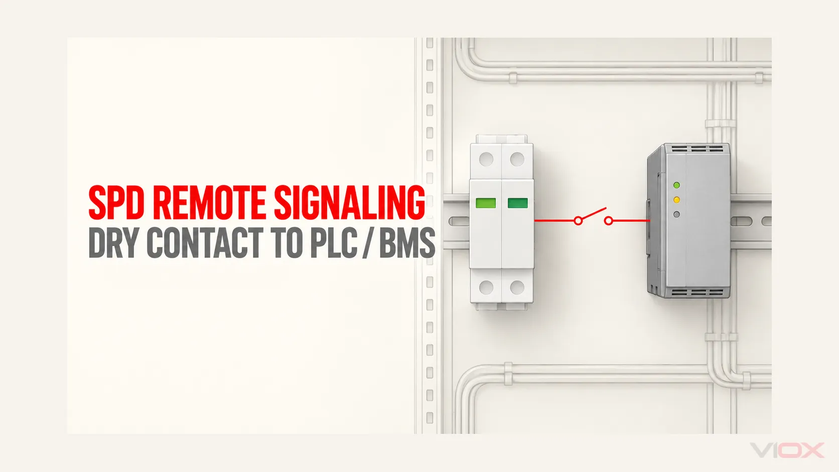
An SPD remote contact is normally a status output, not a surge sensor and not a powered communication port. It can tell a programmable logic controller (PLC), building management system (BMS), supervisory control and data acquisition (SCADA) system, or local alarm that the SPD has changed to a model-defined state.
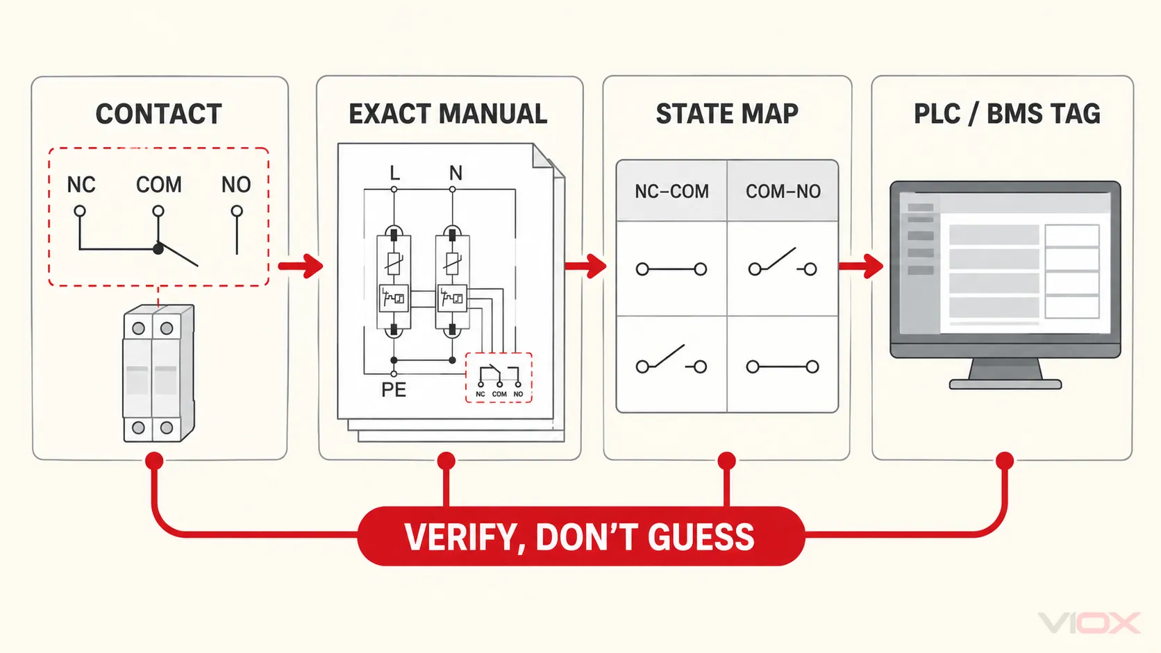
Before connecting COM with NO or NC, verify five things in the exact SPD and control-system documentation: the terminal diagram, the healthy and fault contact states, the contact switching capacity, the digital-input circuit, and any required isolation. Do not infer “healthy” or “fault” from the NO and NC labels alone.
Safety boundary: De-energize exposed electrical parts, apply the site’s lockout/tagout procedure, and verify the de-energized condition with suitable test equipment. Only qualified persons should work on or test equipment where electrical hazards remain. A remote-status contact or green indicator is not proof that the panel is de-energized.
What SPD Remote Signaling Reports
Many power SPDs use a mechanically or electrically operated changeover contact with three terminals:
- COM: the common moving contact;
- NO: the contact path designated normally open;
- NC: the contact path designated normally closed.
The contact is often described as dry, volt-free, potential-free, or Form C. “Dry” means the contact does not itself supply the PLC or alarm voltage. The receiving system must provide a compatible sensing circuit, or an interposing relay must be added.
The contact’s actual meaning depends on the product design. It may change state when an internal disconnector operates, when a removable module is missing, when the monitored protection path is no longer available, or—on some powered monitoring designs—when control power is lost. The exact product manual defines the trigger and contact state.
| The remote contact can usually support | It does not prove |
|---|---|
| A binary healthy/service-required indication defined by the manufacturer | How large the last surge was |
| An alarm input for a PLC, BMS, SCADA system, annunciator, or monitoring relay | How much surge capacity remains |
| Remote awareness when the local status window cannot be inspected routinely | That the SPD is correctly selected or installed |
| A maintenance trigger for the identified SPD location | Which electrical event caused the status change |
| A supervised circuit when the complete loop and input logic are designed for it | That the panel is de-energized or safe to open |
For local window interpretation and replacement boundaries, use the dedicated guide to SPD status indicators and the separate SPD lifespan and MOV aging guide.
For the wider protection role, installation locations and SPD types, begin with what a surge protective device is; this page is limited to the auxiliary status interface.
Verify the Interface Before Wiring
Do not start with a generic online diagram. Start with the documents for the exact SPD suffix and exact input module.
| Verify | What to find | Stop if it is missing or unclear |
|---|---|---|
| SPD model and option | Full model code showing that the remote-contact option is fitted | The base model exists, but the installed suffix or contact option cannot be confirmed |
| Terminal diagram | COM, NO and NC locations; reference state used by the drawing | Terminal labels are unreadable or the manual does not match the device |
| Status truth table | Continuity paths for healthy, fault, module removed and power-loss conditions, where applicable | The design relies only on an assumed “normal” state |
| Contact rating | Permitted AC/DC voltage, current, load type and conductor size | The intended sensing or alarm circuit exceeds any published limit |
| PLC/BMS input | Input voltage, current, source/sink behavior, common arrangement and ON/OFF thresholds | The external supply and input common cannot be matched confidently |
| Isolation and protection | Whether an interposing relay, fused control supply, surge protection, or separation is required | Two systems would be joined through an undocumented common or foreign potential |
The main SPD ratings—such as Uc, Up, In, Imax or Iimp—do not define the auxiliary contact. Treat the contact as a separate control-circuit interface. The SPD datasheet guide explains the main protection ratings; the remote-contact diagram and switching data still need their own verification.
Build a Model-Specific NO/NC/COM Truth Table
NO and NC describe contact positions, but they do not, by themselves, tell the control programmer which state means “SPD healthy.” The internal actuator, removable cartridge arrangement, and reference condition used by the manufacturer determine the result.
Copy the verified states into a project truth table before assigning the PLC tag:
| Physical condition | COM–NO continuity | COM–NC continuity | PLC input | HMI meaning | Evidence |
|---|---|---|---|---|---|
| SPD healthy, all modules installed | From exact manual/test | From exact manual/test | Record during commissioning | SPD HEALTHY |
Model diagram + test record |
| Manufacturer-defined service/fault state | From exact manual/test | From exact manual/test | Record during commissioning | SPD SERVICE REQUIRED |
Approved simulation method |
| Removable module absent, if monitored | Verify | Verify | Verify | SPD MODULE MISSING or combined alarm |
Model manual |
| Control power absent, if relevant | Verify | Verify | Verify | SPD MONITORING UNAVAILABLE or combined alarm |
SPD monitoring architecture |
| Field wire open | Open path at affected input | Open path at affected input | Depends on loop design | CIRCUIT FAULT or combined alarm |
Loop test |
If the device provides only one binary contact, the PLC may not be able to distinguish an SPD fault from a missing module, loss of monitoring power, or broken field wire. Use alarm text that reflects what the circuit actually proves. SPD STATUS NOT HEALTHY—INSPECT is often more defensible than a highly specific diagnosis that the contact cannot make.
Choose NO or NC Logic by Failure Behavior
The correct choice is the one that produces the required system behavior after considering both SPD status and field-circuit faults.
| Monitoring strategy | Intended behavior | Advantage | Limitation |
|---|---|---|---|
| Alarm-on-change using a normally open path | Input changes when the model-defined alarm state closes the selected path | Simple event signaling and low steady-state circuit activity | A broken wire can look the same as the normal open state |
| Supervised loop using a normally closed path | A continuously closed loop opens for the model-defined alarm state | Can also reveal an open conductor or loose terminal | Loss of input supply or another loop fault can produce the same alarm |
| Changeover monitoring with two inputs | PLC observes both NO and NC paths | Can detect some impossible-state or wiring faults | Uses more I/O and still depends on the exact contact mechanism |
| Interposing relay interface | SPD contact switches a compatible relay circuit; relay contacts feed the control system | Separates incompatible voltages, commons, or loads | Adds a coil, contact, protection and failure point that must also be tested |
A supervised NC loop is often useful where loss of the field circuit must not remain invisible. It is not automatically “safer” unless the PLC logic, power-supply monitoring, alarm delay, maintenance response, and proof test are designed around it.
Check the PLC or BMS Input Circuit
A dry contact acts as a switch inside another circuit. It does not generate the input voltage. Before making a connection, answer these questions:
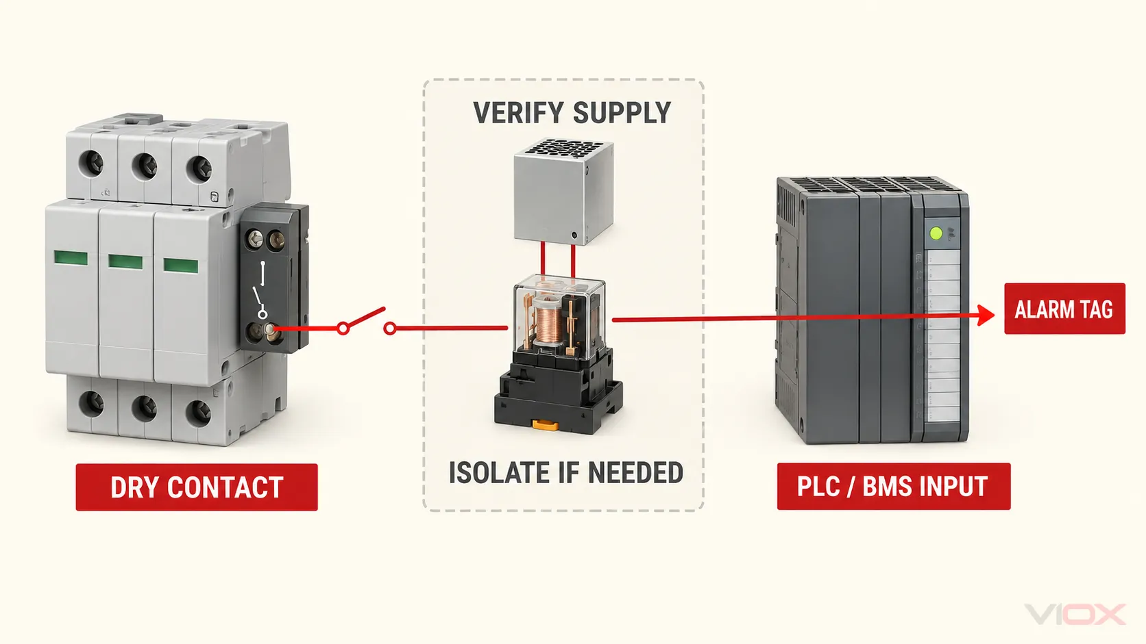
- Where does the sensing voltage come from? Some input modules provide a wetting voltage; others require an external control supply.
- What completes the return path? Confirm the input common and whether the module uses sourcing or sinking logic.
- What current will the contact make and break? Use the input’s actual steady-state and inrush behavior, not only its nominal control voltage.
- Are the systems allowed to share a common? Do not join different panel supplies, grounded references, or remote-site potentials without an approved design.
- Does the SPD contact have the required switching and isolation ratings? A “dry” label is not permission to use any voltage.
- Could induced noise create a false alarm? Route and protect control wiring according to the project’s panel, cable, electromagnetic-compatibility, and manufacturer requirements.
Use an interposing relay or an appropriately isolated input when the contact rating does not match the input circuit, the systems use incompatible references, a larger annunciator load must be driven, or the project requires an isolation boundary that the SPD documentation does not establish.
This remote-status wiring is not the same as surge protection for RS-485, Ethernet, sensor, or telecom conductors. Those lines require their own interface-specific assessment; see the signal surge protector selection guide.
Connection and Commissioning Procedure
The sequence below is a verification workflow, not a replacement for the exact SPD, PLC, BMS, panel and site instructions.
1. Freeze the design inputs
Record the installed SPD model and remote-contact suffix, the destination input module, control voltage, input common, tag name, alarm text, conductor specification, terminal numbers, and approved test method.
2. De-energize and verify
Follow the applicable safe-work procedure. Identify every source—including control power and possible backfeed—then isolate, lock/tag, and verify the condition with suitable test equipment. Do not use the SPD indicator or remote input as the voltage test.
3. Identify terminals from the exact diagram
Match the physical COM, NO and NC markings to the model documentation. If the installed terminal arrangement, suffix, or diagram differs, stop and resolve the mismatch before wiring.
4. Complete the control circuit
Connect only the selected contact path and the compatible input/sensing circuit shown on the approved project drawing. Apply the product’s conductor, termination, segregation and enclosure requirements. Label both ends with the device tag and input reference.
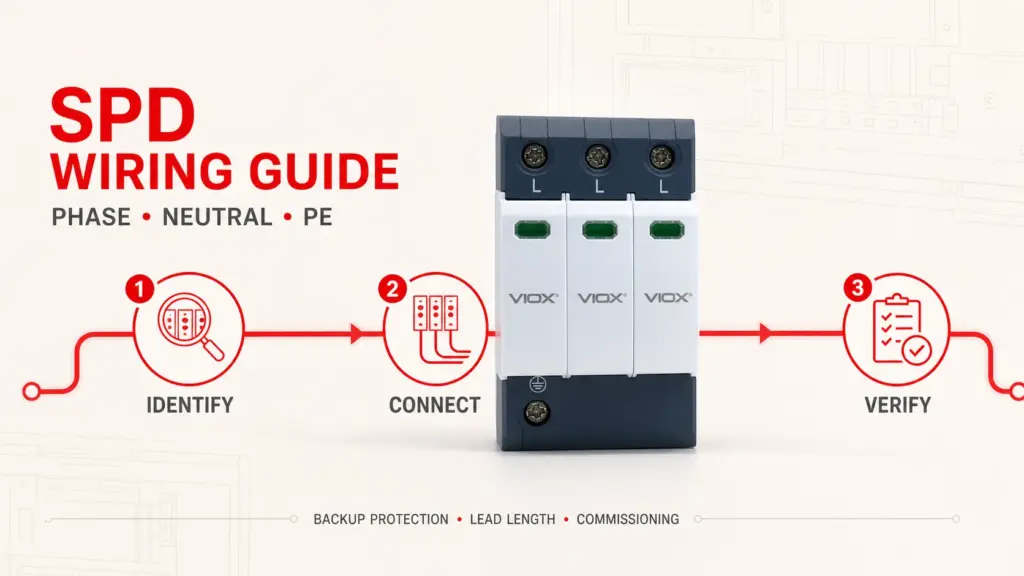
For main power connections, lead routing and backup protection, use the separate SPD wiring guide; this article covers only the auxiliary status circuit.
5. Perform de-energized contact checks
With the remote circuit isolated from external voltage, use an appropriate continuity or resistance test only where the manufacturer permits it. Compare COM–NO and COM–NC with the documented reference state. A result that disagrees with the manual is a stop condition, not something to invert later in software without investigation.
6. Restore power under the approved procedure
Remove temporary test connections, close covers and barriers, clear personnel, and restore power according to the site procedure. Confirm that the local indication and remote input agree with the expected healthy state. Agreement proves the indication path at that moment; it does not validate SPD selection or surge performance.
7. Simulate the service state safely
Use only the manufacturer-approved test feature or simulation method. Do not create an electrical fault, expose live parts, or withdraw a plug-in module while energized unless the exact instructions and qualified work procedure explicitly permit it. If the product provides no safe method to change state, document the portion of the alarm path that could and could not be proven.
8. Verify the complete alarm chain
Confirm the input transition, PLC/BMS tag, HMI text, alarm priority, timestamp, acknowledgment behavior, and maintenance notification. Then restore the SPD and monitoring circuit to the documented healthy condition and verify that the alarm clears correctly.
Commissioning Acceptance Record
An alarm is maintainable only when another technician can identify what was tested and reproduce the result.
| Record field | Required entry |
|---|---|
| SPD identification | Manufacturer, full model/suffix, panel, circuit and device tag |
| Contact evidence | Manual/drawing revision and terminal reference |
| Verified truth table | Healthy and simulated service-state continuity paths |
| Control interface | Input module, channel, supply, common arrangement and interposing device, if used |
| Software mapping | PLC/BMS tag, normal state, alarm state, delay and HMI text |
| Test result | Local indication, input transition, HMI alarm, notification and restoration |
| Limitations | Conditions not simulated or not distinguishable by the contact |
| Sign-off | Test date, qualified person and drawing/as-built revision |
Where several SPDs share one series alarm loop, record that the loop indicates a group alarm rather than the failed unit. Individual inputs improve fault location but consume more I/O and wiring. Choose deliberately; do not let the final topology emerge accidentally during installation.
Troubleshoot an Incorrect Remote Alarm
| Symptom | Likely issue | Safe check | Action |
|---|---|---|---|
| HMI shows an alarm while the local window appears healthy | Logic inverted, wrong contact path, broken supervised loop, or different model-defined state | Compare the live tag logic with the approved truth table; inspect only under the safe-work procedure | Correct the documented mismatch; do not hide it by changing alarm text alone |
| Local indicator shows service/fault but no remote alarm appears | Contact option absent, wrong terminals, open supply/return, failed input, or incomplete alarm mapping | Test each segment of the de-energized circuit and use the approved contact-state simulation | Repair the failed segment and repeat the end-to-end test |
| Alarm changes intermittently | Loose termination, damaged cable, unstable supply, noise coupling, or marginal input threshold | Inspect terminations and trend the input/supply using approved methods | Correct the physical or interface problem; avoid masking it with a long software delay |
| Alarm does not reveal which module failed | The contact provides only one common status output | Check the product architecture and inspect the tagged SPD safely | Use accurate combined alarm wording or specify more granular monitoring next time |
| Alarm remains after replacement | Module not fully seated, contact mechanism not reset, wrong replacement, latched PLC logic, or another fault remains | Compare local state, contact continuity and software latch status with the manuals | Resolve the remaining condition before declaring the protection restored |
Remote signaling accelerates awareness; it does not diagnose the cause. If the local status has changed, follow the product inspection and replacement instructions rather than assuming that the last surge destroyed the SPD.
VIOX VSP1-C40/2(S): A Bounded Data Example
The VIOX VSP1-C40/2(S) product page lists remote contacts as an optional feature and publishes an NC/COM/NO connection diagram. Its published remote-contact data are:
| Item | Published VSP1-C40/2(S) value |
|---|---|
| Remote-contact option | Optional |
| AC switching capacity | 250 V / 0.5 A |
| DC switching capacity | 250 V / 0.1 A; 125 V / 0.2 A; 75 V / 0.5 A |
| Maximum remote-contact conductor cross-section | 16 AWG solid / 1.5 mm² solid |
These values apply to the cited model page; they are not a VIOX-wide rating and do not replace verification of the ordered suffix, load type, control-system input, terminal diagram, current datasheet, or quotation documentation. They also show why AC and DC contact limits must not be treated as interchangeable.
When comparing a different model, request the exact remote-contact drawing and switching data. The VIOX SPD product range provides the family-level starting point, while the model documentation controls the final interface.
Remote-Signaling Specification Checklist
Before releasing the panel drawing or request for quotation, confirm:
- exact SPD model and remote-contact option suffix;
- contact type and the manufacturer-defined healthy/fault states;
- AC and DC switching capacity for the intended circuit;
- input voltage, current, common arrangement and ON/OFF thresholds;
- need for an interposing relay or isolated input;
- behavior for module removal, loss of power and broken field wire;
- individual versus grouped alarm topology;
- terminal and conductor requirements;
- device tag, PLC/BMS tag and unambiguous alarm text;
- manufacturer-approved simulation method and acceptance record;
- safe isolation, test and restoration procedure.
For model-specific support, send the SPD model, system voltage, remote-input details and required alarm behavior to [email protected]. VIOX can confirm available product documentation and remote-contact options for the proposed configuration.
Standards and Safety Boundary
IEC 61643-01:2024 provides common requirements and test methods for low-voltage SPDs, while IEC 61643-11:2025 addresses SPDs connected to AC low-voltage power systems. Their scope should not be turned into a claim that every compliant SPD includes remote signaling or uses one universal contact state.
IEC 60947-5-1 covers control-circuit devices and switching elements used for functions including signaling and interlocking. That scope is useful when reviewing the control interface, but it is not evidence that a particular SPD auxiliary contact is certified unless the product documentation says so.
For work practices in the United States, OSHA 29 CFR 1910.333 requires safety-related work practices around electrical hazards and verification of the de-energized condition by a qualified person. Local regulations, project specifications, manufacturer instructions, and the authority having jurisdiction still control the installation.