

On this page
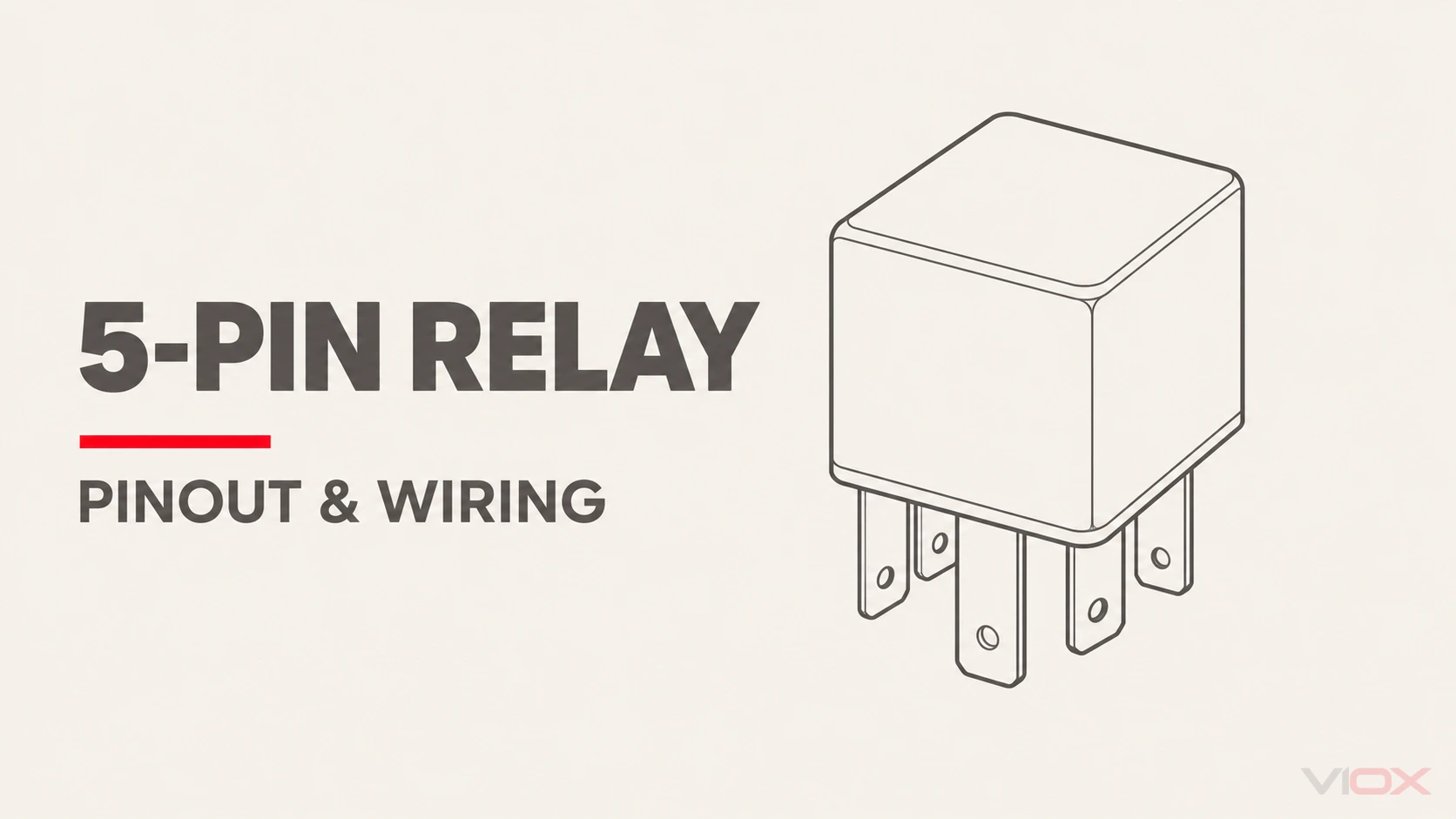
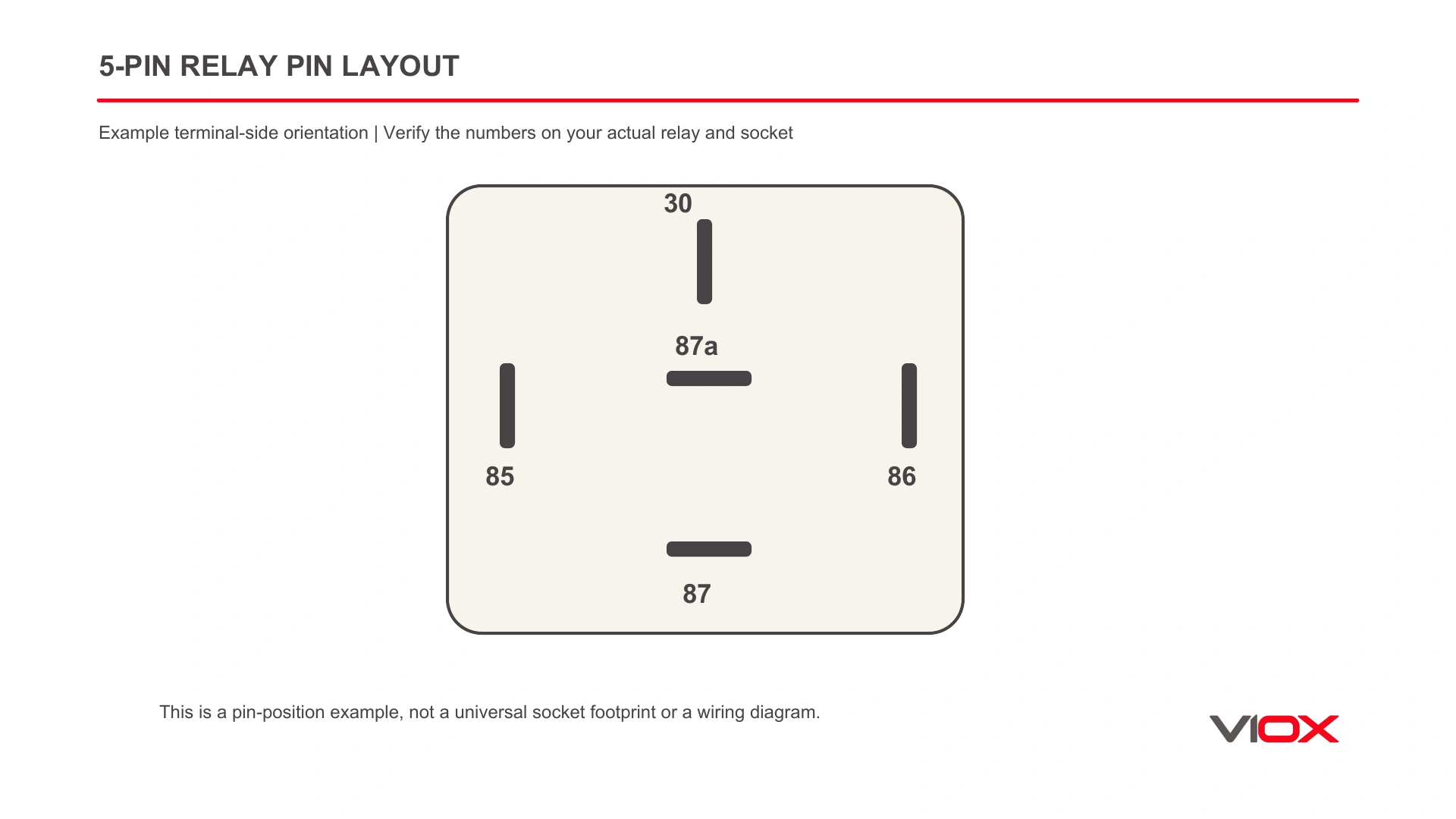
A five-pin automotive changeover relay uses a small coil-control current to switch a separate load circuit. With the coil OFF, terminal 30 connects to 87a. With the coil ON, 30 connects to 87. Terminals 85 and 86 operate the coil; they are not the load terminals.
This guide covers the automotive relay marked 30, 85, 86, 87 and 87a. Five physical pins alone do not establish that arrangement. For other operating principles and relay families, see the different types of relays.
Relay Pin Configuration
Start with the diagram printed on the relay and the socket’s terminal numbers. The following table describes the protected, negative-ground example used in this guide, with the control switch on the positive side of the coil.
| Pin | Name | Connects to | At rest: coil OFF | Energized: coil ON |
|---|---|---|---|---|
| 30 | Common / COM | Fused load supply in this example | Connected to 87a; open to 87 | Connected to 87; open to 87a |
| 87 | Normally Open / NO | Load A positive input | Open from 30 | Connected to 30 |
| 87a | Normally Closed / NC | Optional load B positive input | Connected to 30 | Open from 30 |
| 85 | Coil return / minus | Battery negative or suitable chassis return | Return connection remains present | Carries coil return current |
| 86 | Coil control / plus | Protected positive supply through the control switch | Control switch open | Control switch closed; coil driven |
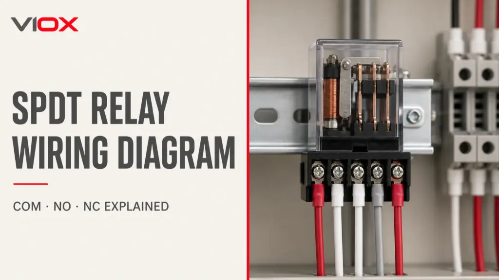
The contact arrangement is single pole, double throw (SPDT). “Normally” describes the coil-de-energized condition, not whether the vehicle or accessory is normally running. The broader SPDT relay terminal and wiring guide explains other numbering systems and contact arrangements.
Is 85 or 86 Positive?
For the conventional circuit illustrated here, 86 is coil positive and 85 is coil negative. Apply that convention only after checking the case diagram:
- A plain, non-latching DC coil without polarity-sensitive components can usually operate with either polarity. The convention still helps keep the harness understandable.
- A coil with an ordinary parallel suppression resistor is generally non-polarized, provided no other polarity-sensitive electronics are present.
- A coil with a parallel flyback diode requires the marked polarity. In this example, the diode cathode faces 86/positive and the anode faces 85/negative. Reversing the supply forward-biases the diode and can create a near-short across the control supply, damage the diode or driver, or open its protection.
Do not identify the suppression type from the relay’s color. Look for its internal circuit symbol and exact part documentation. A similar-looking replacement may use a different suppression arrangement.
5-Pin Relay Component Breakdown
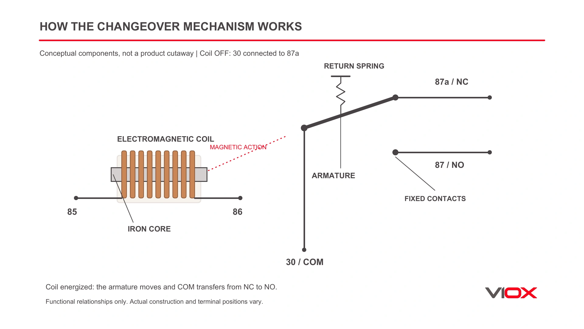
A five-pin changeover relay consists of several components working together:
- Electromagnetic coil: Copper wire wound around a magnetic core produces the actuating magnetic field.
- Armature: A movable member responds to the coil’s magnetic field and moves the contact mechanism.
- Common contact: The shared switching connection, terminal 30 in this automotive convention.
- Fixed NO and NC contacts: These connect to terminals 87 and 87a respectively.
- Return spring: Restores the normal contact position when the coil is de-energized.
- Housing and terminals: Enclose the mechanism and provide the external connections.
The relay coil-voltage guide distinguishes rated coil voltage from pick-up, holding and drop-out behavior. A battery supply label alone does not establish the correct operating range for a particular coil.
4-Pin vs 5-Pin Relay
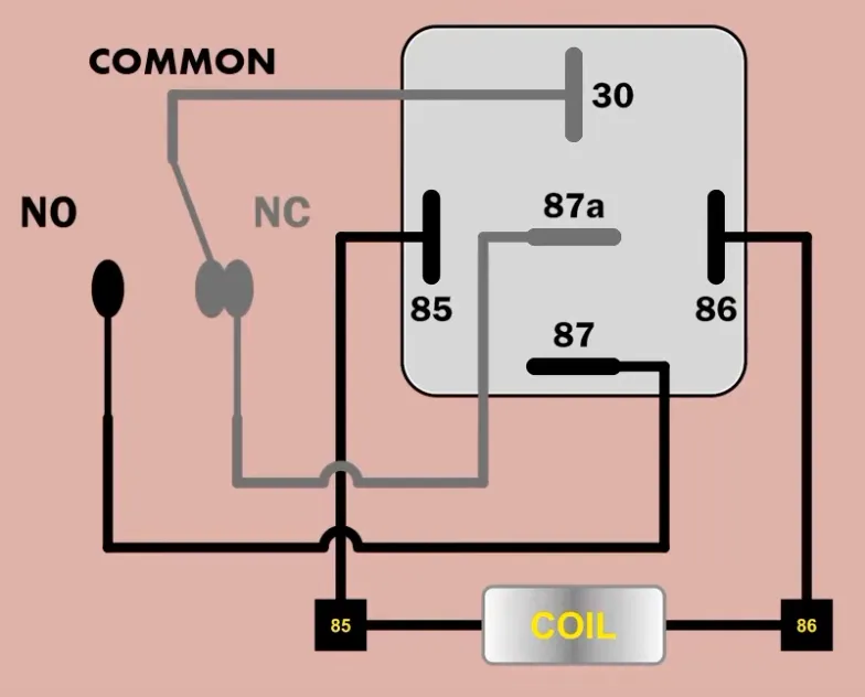
A common four-pin automotive make relay has two coil terminals plus 30 and 87. It provides a normally open path for turning one load on and off. The five-pin changeover version adds the 87a normally closed path, useful when a circuit needs an alternative resting state.
However, not every five-pin relay is changeover. Some have two outputs both marked 87, which may energize together. Those are not interchangeable with an 87/87a relay simply because the housing and pin count match.
A compatible five-pin changeover relay may serve a four-pin normally open application with 87a unused. Confirm the socket accepts the extra blade, the terminal positions match, the coil voltage and suppression are compatible, and the load ratings are suitable. Do not force a relay into a socket, cut off a blade, or assume the extra position is safely unconnected. For an ordinary one-load ON/OFF job, a correctly specified four-pin relay may be sufficient.
Relay Operation Explained
The operation is based on electromagnetic principles. When voltage is applied across the coil, its magnetic field attracts the armature. That movement transfers the common contact from its normal position.
In the normal steady states, the changeover contact selects one path: 30-87a at rest, or 30-87 when energized. It does not supply two simultaneous normally open outputs. Ordinary changeover contacts commonly break the old connection before making the new one; the exact switching sequence remains a datasheet property.
The coil circuit and contact circuit are electrically separate inside the relay, so their operating voltages can differ within the product’s specifications. That separation does not authorize switching an arbitrary higher voltage. Contact voltage, load type, insulation and socket suitability must all be checked.
For example, a marking such as “12V 30A” may identify coil voltage and a contact-current rating, but it is not a complete application specification. Confirm how the manufacturer defines each value, including any different NO/NC ratings and the permitted load. Do not infer mains suitability from an automotive relay’s coil marking.
Wiring Instructions: One Complete Negative-Ground Example
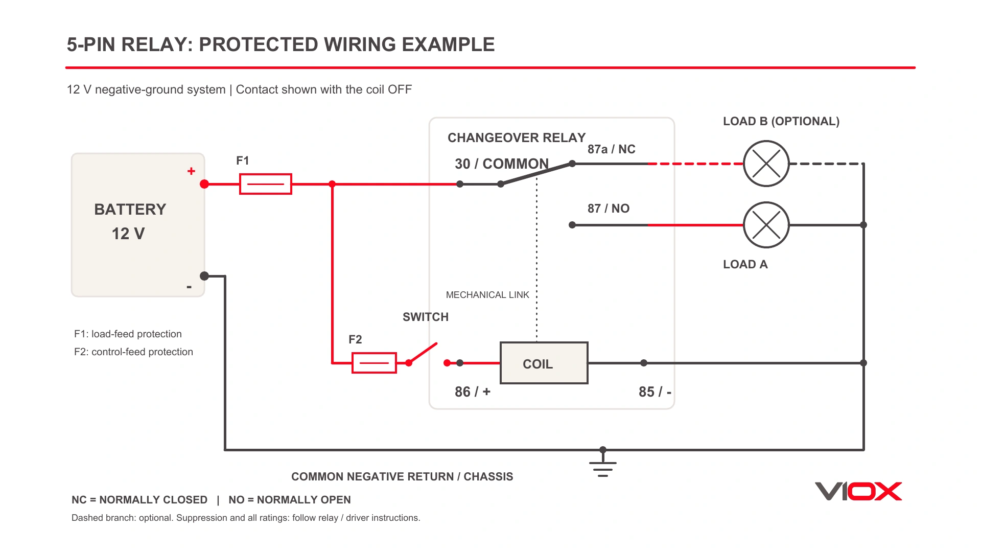
The diagram below uses a 12 V negative-ground circuit, a positive-side coil switch, a main load fuse and a separately protected control branch. It is an accessory-circuit example, not permission to alter an ECU output, safety circuit or high-voltage vehicle system.
Download the one-page printable wiring diagram (PDF).
1. Isolate the Supply Before Touching the Wiring
Follow the vehicle or equipment service procedure. For this negative-ground example, disconnect the battery negative connection as directed and isolate any additional source that could energize the circuit. Keep the relay, battery terminals and loose conductors protected against accidental bridging. If the correct isolation procedure is unclear, use a qualified automotive electrician.
2. Bring the Protected Load Supply to Terminal 30
Connect battery positive through the main fuse to terminal 30. Locate the fuse close to the source so the feed conductor is protected. Select protection for the actual load, wire and installation, consistent with the relay and socket ratings; no universal fuse size follows from the number of relay pins.
In this example, 30 is the protected common supply and 87/87a are selected outputs. That convention makes the two states easy to check. The contacts are not inherently one-way devices, but changing the supply point changes how the NC path behaves and requires a deliberate circuit design.
3. Connect the Coil-Control Circuit
Run a protected positive control feed through the control switch to 86. Connect 85 to the suitable negative return. The drawing derives that control feed downstream of the main fuse and includes separate control protection where the smaller control branch begins.
This is positive-side switching. Some vehicles switch the negative side instead, but that requires its own complete, verified circuit; do not combine parts of two diagrams. Do not connect an ECU output without its manufacturer’s interface instructions.
4. Connect the Loads and Their Returns
Connect load A’s positive input to 87 and its negative connection to the return. It runs when the coil operates. If required, connect load B to 87a with its own suitable return; it runs with the coil off while the common supply is available.
If 87a is unused, leave it electrically unconnected and suitably insulated. It can be live in the resting state whenever 30 has supply. Protect the socket, terminals and conductors against accidental contact; an unused NC output is not automatically a dead output.
5. Verify Suppression Before Connecting an Electronic Driver
Read the case diagram for a built-in diode or resistor. When external suppression is needed, select it according to the relay and driver documentation. An ordinary flyback diode, when specified, is reverse-biased in normal operation: cathode to the positive coil side, anode to the negative side.
Do not automatically add one across every ECU-driven coil. The driver may already provide clamping, and suppression choice changes release behavior. Avoid duplicating or defeating an existing protection scheme.
6. Test Both States
Review all wiring before restoring supply under the service procedure. With the coil unpowered, the optional NC load should operate and the NO load should not. Close the control switch: the relay should operate, load A should run and load B should stop. Open it again and verify return to the resting state.
An audible click does not prove the load contacts conduct correctly. If the expected load does not operate, check the protected feed to 30, the selected output and the load return. Isolate again before moving wires or checking continuity. For other verified circuit examples, see the full SPDT wiring guide.
Common Applications
Automotive systems use appropriately rated relays for headlights, auxiliary lighting, engine cooling fans and fuel pumps. Changeover contacts can select between two approved accessory states, such as alternative lamp modes, when the equipment’s own wiring permits it.
Power windows and central locking may use relays within a larger control arrangement. A single SPDT relay does not, by itself, reverse both conductors of a two-wire motor. Similarly, do not assume one changeover relay can safely select every fan’s high/low speed connections; the motor and vehicle diagram determine that arrangement.
An ordinary automotive relay is not a safety relay, an emergency-stop architecture or a mains changeover switch. Keep its use within the documented component ratings and the complete system design.
Frequently Asked Questions
Is pin 85 or 86 positive?
The example uses 86 positive and 85 negative. Plain or resistor-suppressed non-latching DC coils are generally non-polarized, but a diode-suppressed coil must follow its marked polarity. Check the exact case diagram before connecting the supply.
Can I swap pins 30 and 87?
Not as an unexamined substitution in this diagram. A simple dry-contact NO path can sometimes carry current in either direction, but swapping the supply and output changes the NC-path behavior. Keep the protected supply on 30 for this example and follow the actual relay’s instructions.
Can a 5-pin relay replace a 4-pin relay?
Sometimes, if it is the correct changeover type, the socket layout and extra-blade clearance match, and the coil, suppression and load ratings are compatible. The unused 87a terminal must remain safely unconnected. A dual-87 relay requires a separate compatibility check.
The relay clicks but the load does not run – what do I check?
Check the fuse and supply feeding 30, the connection from 87 to the intended load, and the load’s return. Then assess contact condition and coil supply under the proper test procedure. Use the SPDT troubleshooting table for deeper diagnosis; sound alone does not prove a healthy relay.
Conclusion
Read the terminal numbers and case diagram first. For this changeover example, coil OFF connects 30 to 87a; coil ON connects 30 to 87. Keep coil polarity, protected load supply and return paths consistent with the exact relay and the vehicle’s instructions, then verify both operating states.