On this page
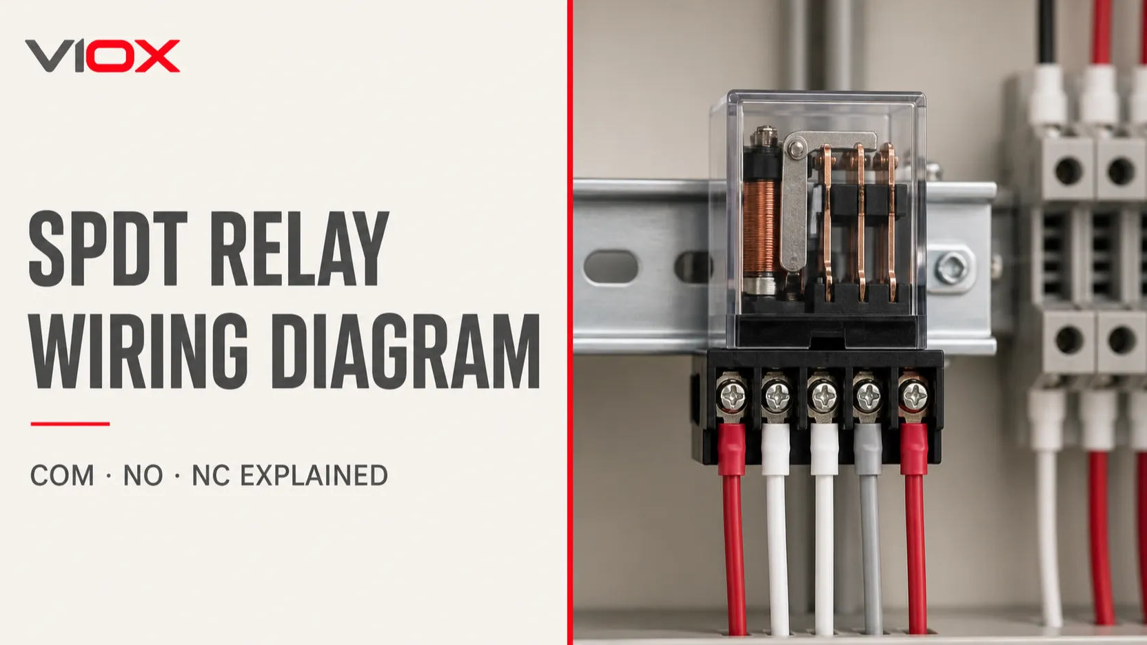
An SPDT relay has five functional terminals: two for the coil and three for the changeover contact—Common (COM), Normally Closed (NC), and Normally Open (NO). With the coil de-energized, COM is connected to NC. When the rated coil voltage is applied, the relay transfers COM from NC to NO.
Coil OFF:  COM ─── NC      COM  x  NO
Coil ON:   COM  x  NC      COM ─── NO
For a load that should turn on only when the relay operates, wire the switched supply through COM and NO. For a load that should remain on until the relay operates, use COM and NC. The coil circuit and contact circuit are electrically separate, so never assume their voltage or current ratings are the same.
Safety: Isolate every power source before wiring or continuity testing. Use the terminal diagram and ratings for the exact relay and socket. For mains-voltage work, follow applicable wiring rules and use qualified personnel.
SPDT Relay Wiring at a Glance
| Terminal | Function | State with coil OFF | State with coil ON |
|---|---|---|---|
| A1 and A2, or coil pins | Energize the electromagnetic coil | No magnetic actuation | Relay armature operates |
| COM | Moving contact shared by both paths | Connected to NC | Connected to NO |
| NC | Normally closed contact | Conducting to COM | Open from COM |
| NO | Normally open contact | Open from COM | Conducting to COM |
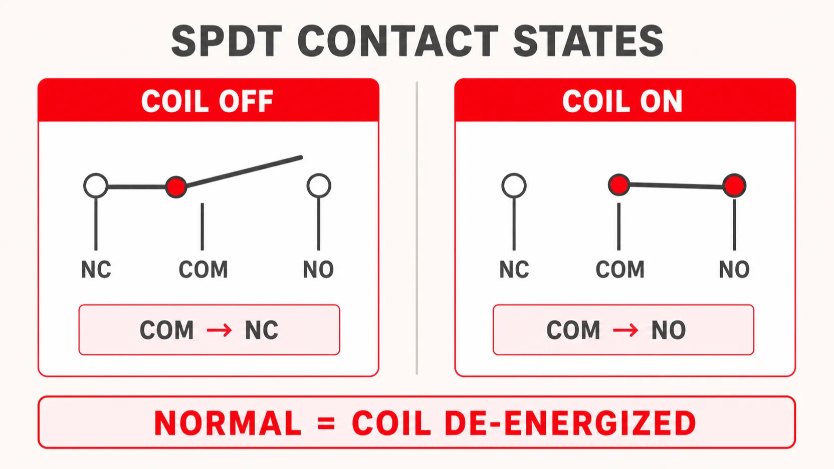
SPDT means single pole, double throw. “Single pole” means the relay switches one common circuit. “Double throw” means that common can connect to either of two contacts. This arrangement is also commonly described as a changeover contact or Form C contact.
How an SPDT Relay Works
An electromechanical SPDT relay contains a coil, magnetic core, armature, return spring, and one changeover contact set.
- Coil de-energized: The return spring holds the armature in its normal position. COM touches NC.
- Rated coil voltage applied: Coil current creates a magnetic field that pulls the armature.
- Contact transfer: COM separates from NC and closes onto NO. Most ordinary changeover relays use break-before-make action, but the relay datasheet is the authority.
- Coil voltage removed: The magnetic field collapses and the spring returns COM to NC.
The words normally open and normally closed always describe the relay with its coil de-energized. They do not describe whether the external equipment is normally running.
The coil may be controlled by a switch, programmable logic controller (PLC), sensor output, thermostat, or transistor. The contacts can switch a separate circuit within the relay’s specified contact ratings. This separation is why a low-voltage control signal can command another circuit, but it does not permit arbitrary voltage or current: insulation category, load type, and contact ratings still apply.
Identifying the Five SPDT Relay Terminals
Do not identify terminals by physical position alone. Pin layouts vary between PCB relays, plug-in industrial relays, automotive relays, and relay modules—even when all of them are described as SPDT.
IEC-style terminal markings
A common IEC-style marking scheme for one changeover contact is:
| Marking | Typical function |
|---|---|
| A1, A2 | Coil |
| 11 | COM |
| 12 | NC |
| 14 | NO |
Additional changeover poles often use 21–22–24, 31–32–34, and so on. Treat this as a numbering convention, not a substitute for the manufacturer’s diagram.
Common automotive 5-pin markings
Many automotive changeover relays use:
| Pin | Typical function |
|---|---|
| 85, 86 | Coil |
| 30 | COM |
| 87a | NC |
| 87 | NO |
Some relays contain a suppression diode or resistor across the coil. A diode makes coil polarity important, so check the case marking before connecting pins 85 and 86. Also distinguish an 87a changeover relay from relays that provide two terminals both marked 87; the latter may have two simultaneous NO outputs rather than an NC contact.
How to identify an unknown relay with a multimeter
Only perform these tests with the relay disconnected from all circuits.
- Read the diagram printed on the relay or its datasheet first.
- In resistance mode, locate the pair with a stable finite resistance; these are usually the coil terminals. Do not energize them yet.
- In continuity mode, find the contact pair that is closed with the coil off. These are COM and NC.
- The remaining contact is NO.
- Apply only the relay’s rated coil voltage from a current-limited source. COM–NC should open and COM–NO should close.
- If you still cannot distinguish COM from NC, compare both contact states with the manufacturer’s diagram. Do not guess.
A built-in LED, diode, resistor, timer circuit, or other electronics can affect resistance readings. For those devices, the datasheet is essential.
Basic SPDT Relay Wiring Diagrams
1. Load turns ON when the coil energizes
Use the normally open contact when the load should operate only after the relay receives a control signal.
CONTROL SIDE                      CONTACT SIDE

+Vcontrol ── switch ── A1         +Vsupply ── fuse ── COM
                       ( coil )
0Vcontrol ──────────── A2                               NO ── load ── return
                                                       NC ── not used
Sequence:
- Coil off: COM–NO is open, so the load is off.
- Coil on: COM–NO closes, so current flows through the load.
Typical uses include enabling a contactor coil, solenoid valve, indicator, fan, or alarm when a controller output becomes active.
2. Load turns OFF when the coil energizes
Use the normally closed contact when the load should operate in the relay’s resting state and stop when the coil operates.
+Vsupply ── fuse ── COM

                      NC ── load ── return
                      NO ── not used
Sequence:
- Coil off: COM–NC is closed, so the load is on.
- Coil on: COM transfers to NO, opening the NC load circuit.
This topology can provide inverted control logic. It should not automatically be described as “fail-safe”: whether a system fails safely depends on the complete circuit, failure modes, monitoring, and applicable safety requirements.
3. Changeover between two loads
An SPDT relay can select between two separate loads that share one supply path, provided both circuits are compatible with the relay contact and isolation ratings.
                         ┌── NC ── Load A ── return
+Vsupply ── fuse ── COM ─┤
                         └── NO ── Load B ── return
With the coil off, Load A is supplied. With the coil on, Load B is supplied. Because ordinary changeover contacts are typically break-before-make, there may be a brief interval when neither load is connected.
Driving a DC SPDT Relay from a PLC or Transistor
A PLC or microcontroller output may not be able to supply the coil current directly. A transistor or MOSFET driver is therefore commonly placed between the controller and coil.
                 +Vcoil
                    │
                    ├──── A1
                    │     coil
              diode ┤     A2 ───── collector/drain
          cathode ──┘                 transistor
          anode  ───────────────── emitter/source ── 0V

Controller output ── current-limiting/gate network ── transistor control
Controller 0V and driver 0V connected as required by the design
For a plain DC coil, a reverse-biased flyback diode across the coil limits the voltage produced when coil current is interrupted. Connect its cathode to the positive coil side and anode to the switched negative side. Some relays or modules already contain suppression; adding another device without reviewing the circuit can change release behavior.
A simple diode can increase relay release time. Where fast dropout matters, the relay manufacturer may recommend a diode-plus-Zener, transient-voltage suppressor, or another suppression network. A standard diode cannot be used as the equivalent suppression method directly across an AC coil; use a solution specified for the AC relay and driver.
Coil suppression protects the driver side. An inductive load switched by the contacts—such as a solenoid, contactor coil, or motor—may need separate suppression to limit contact arcing and electrical noise.
Three Practical SPDT Relay Wiring Examples
Example 1: 24 V DC sensor controlling a warning lamp
Suppose a sensor output drives a 24 V DC relay coil and the lamp should illuminate only when the sensor activates.
- Connect the sensor-controlled 24 V supply to A1 and the appropriate return to A2, following the output type and relay polarity.
- Protect the coil driver with the specified suppression method.
- Route the lamp’s protected supply to COM.
- Connect NO to the lamp and the other lamp terminal to its return.
The lamp circuit remains open until the sensor energizes the relay. Verify that the sensor output can drive the coil or add an interface driver.
Example 2: Green/red status indication with one changeover contact
One SPDT contact can alternate two indicators:
- Protected indicator supply to COM
- NC to the green indicator
- NO to the red indicator
- Both indicator returns connected to the appropriate return
With the coil off, green is on. When the coil energizes, green switches off and red switches on. Confirm that the two indicator circuits can share the selected common and that their combined design stays within the contact ratings.
Example 3: Interposing relay between a PLC and contactor coil
An SPDT interface relay can isolate a PLC output from a contactor control circuit:
- PLC output energizes the interface relay coil.
- The contactor control voltage enters COM through the required protective and control devices.
- NO feeds the contactor coil, so the contactor operates when the PLC output is active.
- NC may remain unused or provide a separate status path if the design permits.
The interface relay does not replace overload protection, short-circuit protection, emergency-stop architecture, or required safety relays. Select it for the actual contactor-coil inrush, steady-state load, switching frequency, control voltage, and applicable coordination requirements.
Contact Ratings: Why “10 A” Is Not the Whole Specification
Relay contact capability depends on more than the headline current printed on the case.
| Selection item | What to verify |
|---|---|
| Coil voltage and type | Exact AC or DC rating, tolerance, consumption, polarity, and built-in suppression |
| Contact voltage/current | Rating for the actual AC or DC circuit, not a different test condition |
| Load category | Resistive, lamp, solenoid, contactor coil, motor, or capacitive load |
| Inrush and breaking duty | Starting/inrush current and the current interrupted when contacts open |
| Minimum switching load | Important for low-level signals where ordinary power contacts may be unreliable |
| Electrical and mechanical life | Manufacturer curves at the actual load and switching frequency |
| Isolation and environment | Required clearances, socket, enclosure, pollution conditions, temperature, and approvals |
DC loads can be harder to interrupt because the arc does not benefit from a natural current zero crossing. Inductive loads also produce transient voltage when switched. Always use the manufacturer’s load-specific contact data; do not apply a resistive AC rating to a DC motor or solenoid by assumption.
Common SPDT Relay Wiring Mistakes
Confusing COM with the coil common
COM belongs to the contact set. It is not a coil return or universal circuit ground. The two coil terminals form one circuit; COM, NC, and NO form another.
Defining NO and NC while the coil is energized
“Normal” means coil off. If terminal identification begins with the energized state, NO and NC are easily reversed.
Applying the load voltage to the coil
A relay may switch a voltage different from its coil voltage. The permitted values come from separate coil and contact specifications. Applying 120 V to a 24 V coil is not made safe because the contacts are rated for 120 V.
Assuming every five-pin relay has the same layout
Five functional terminals do not guarantee identical pin positions or numbering. Verify the exact part number and whether the diagram is a top view, bottom view, or socket view.
Omitting transient suppression
An unsuppressed DC coil can damage a transistor output or produce electromagnetic interference. An inductive contact load can arc even if the coil is suppressed. Review both sides separately.
Switching a motor directly without checking duty
Motor inrush and inductive interruption can greatly exceed steady-state expectations. A relay suitable for a resistive load at a stated current may not be suitable for a motor at the same current.
SPDT Relay Troubleshooting Table
| Symptom | Likely cause | Safe check | Corrective direction |
|---|---|---|---|
| Relay does not click | Wrong coil voltage, insufficient driver current, wiring error, or open coil | Measure the voltage at A1–A2 during the command and compare with the datasheet | Correct the control circuit or replace a confirmed failed relay |
| Relay clicks but load stays off | Load wired to NC instead of NO, open fuse, contact damage, or missing return path | Isolate power and test COM–NO continuity with the coil operated | Correct wiring and inspect the protected load circuit |
| Load is on in the wrong state | NO and NC reversed | With power isolated, continuity-test the resting contact state | Move the load path to the required contact |
| Controller resets when relay turns off | Coil transient or poor supply/ground layout | Check for specified coil suppression and wiring separation | Add the manufacturer-appropriate suppression and improve layout |
| Contacts stick or fail early | Excessive inrush, inductive arcing, short circuit, or unsuitable contact material | Compare actual load duty with the relay utilization data | Use proper suppression or a correctly rated relay/contactor |
| Relay chatters | Coil voltage sag, unstable control signal, or loose termination | Monitor coil voltage during operation | Stabilize the control supply and repair terminations |
Never perform resistance or continuity measurements on an energized circuit. A click confirms mechanical movement, not necessarily healthy contacts.
SPDT vs SPST vs DPDT: Which Contact Arrangement Do You Need?
| Contact form | What it does | Typical use |
|---|---|---|
| SPST-NO | Closes one path when energized | Simple load enable |
| SPST-NC | Opens one path when energized | Simple inverted control |
| SPDT | Transfers one common between NC and NO | Select one of two paths or provide either NO/NC logic |
| DPDT | Transfers two independent commons together | Switch two isolated paths or reverse polarity in a properly designed circuit |
Use SPDT when one circuit needs changeover action. If two independent circuits must change state together, use DPDT or another suitable multi-pole device. One SPDT relay alone cannot reverse the polarity of a two-wire DC motor; that requires a DPDT arrangement or two appropriately interlocked SPDT relays.
For a deeper comparison, see SPDT vs DPDT relay wiring and contact arrangements and SPST vs SPDT vs DPST vs DPDT.
SPDT Relay Wiring Checklist
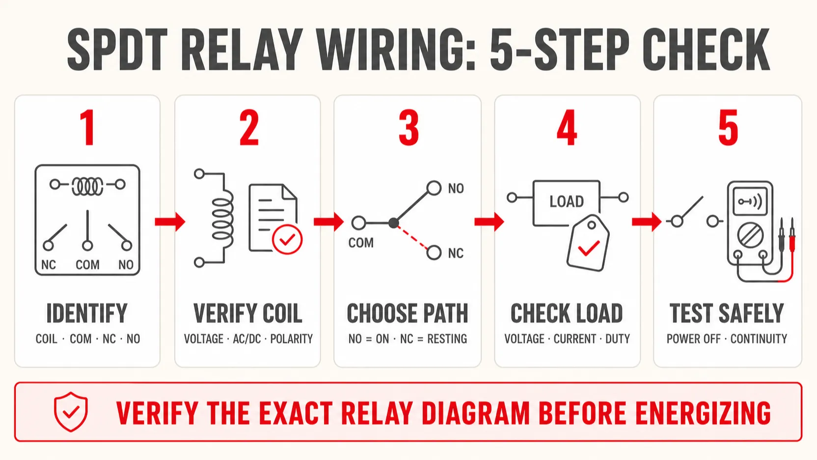
Before energizing the circuit:
- Confirm the exact relay part number and terminal-view orientation.
- Match A1/A2 or coil pins to the specified coil voltage and AC/DC type.
- Check whether coil polarity matters because of an internal LED or diode.
- Identify COM, NC, and NO from the diagram—not physical position.
- Decide the required unpowered state before choosing NO or NC.
- Protect the supply and conductors for the circuit being switched.
- Verify contact ratings for voltage, AC/DC duty, load type, inrush, and switching frequency.
- Add appropriate suppression to the coil driver and any inductive load.
- Maintain required separation between control and higher-voltage wiring.
- Isolate power, inspect the wiring, and continuity-test before commissioning.
For timed changeover applications, the same contact logic applies after the selected timing function. See the VIOX time-delay relay wiring guide for A1/A2, control-input, and timed-contact examples. Buyers and panel builders evaluating relay formats can also review VIOX’s timer relay manufacturing capabilities.
Frequently Asked Questions
What are the five pins on an SPDT relay?
They are two coil terminals plus COM, NC, and NO. Physical pin numbers vary. Common IEC-style markings are A1/A2, 11/12/14, while many automotive relays use 85/86, 30/87a/87. Always verify the exact datasheet.
Do I connect the supply to COM or the load to COM?
Either direction may be electrically possible for a simple dry contact, but a common convention is to route the protected supply into COM and take the selected output from NO or NC to the load. The final design must account for protection, grounding, polarity, isolation, and manufacturer instructions.
Should I use NO or NC?
Use NO when the load should turn on after the coil energizes. Use NC when the load should conduct with the coil de-energized and turn off when it energizes. Evaluate the required behavior during loss of control power before deciding.
Can a 12 V relay switch 120 V or 230 V?
The “12 V” marking may describe only the coil. Whether the contacts may switch mains voltage depends on their explicit ratings, load type, insulation, socket, enclosure, approvals, and installation rules. Never infer contact capability from coil voltage.
Does an SPDT relay require a flyback diode?
A semiconductor-driven plain DC coil normally needs suitable transient suppression. A reverse-biased diode is common, but it can slow release. Relays with internal suppression and AC coils require different treatment. Follow the relay and driver manufacturers’ recommendations.
How do I know whether a relay is energized?
An audible click or indicator can help, but neither proves correct contact operation. Measure the coil voltage and, with the circuit safely isolated, confirm contact continuity in both states.
Can one SPDT relay reverse a DC motor?
No. Reversing a two-wire DC motor requires reversing both conductors, typically using a DPDT contact arrangement or two suitably rated and interlocked SPDT relays.
Conclusion
Correct SPDT relay wiring starts with one simple rule: coil off connects COM to NC; coil on connects COM to NO. The rest of the design depends on identifying the actual terminals, matching the coil supply, selecting the intended unpowered state, checking the contacts against the real load, and controlling transients on both the coil and load sides.
Never rely on a generic five-pin diagram when an exact relay datasheet is available. A correct terminal map and load-specific rating check are more important than the physical appearance of the relay.