On this page
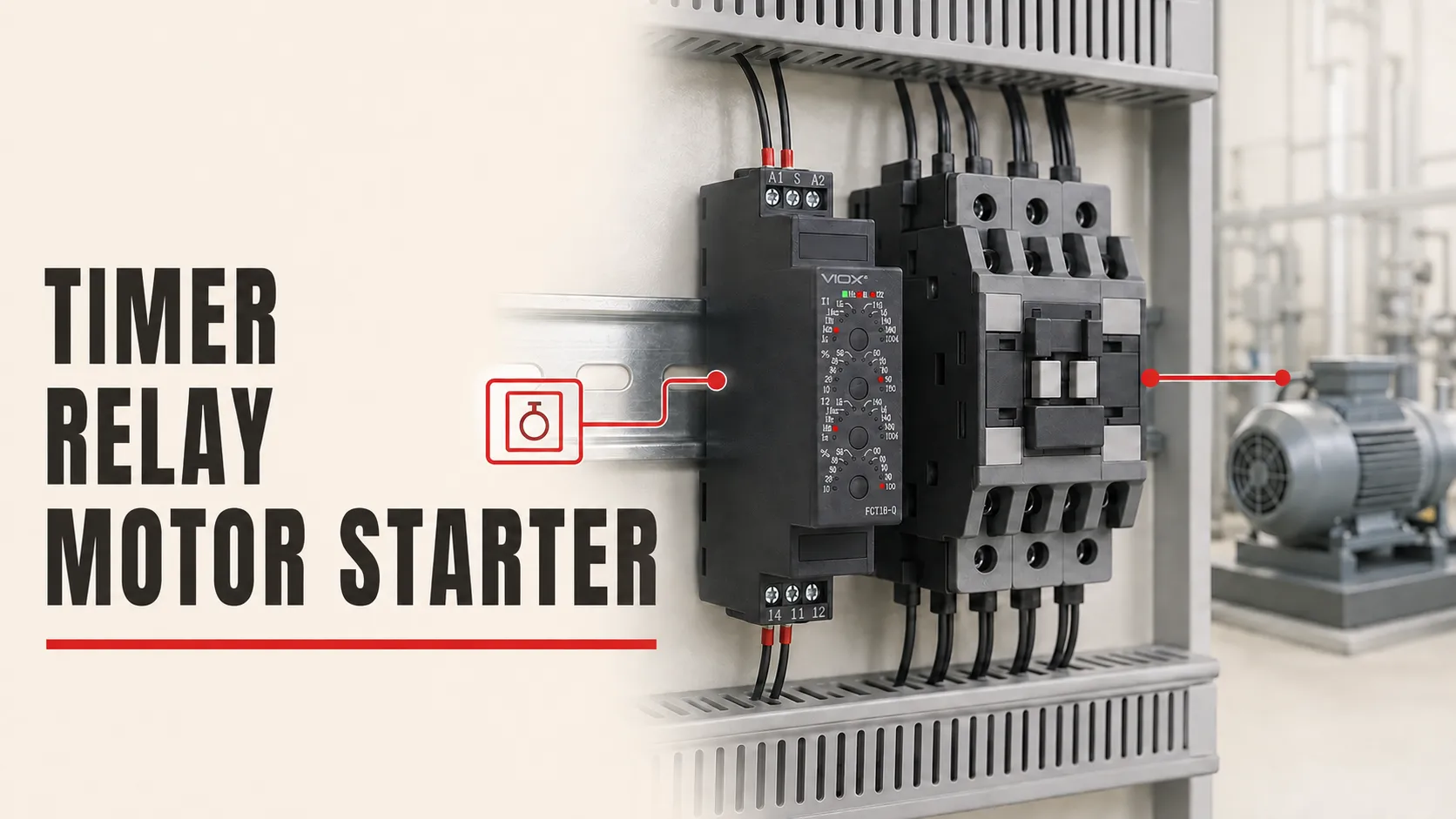
A time relay belongs in the motor starter control circuit, not in the motor power circuit. For a delayed start, use an on-delay function so the timer’s timed normally open output energizes the contactor coil only after the command has remained present for the set time. The normally closed stop and overload contacts must remain able to remove control power from both the timing path and the contactor-coil path.
This guide shows the control logic and commissioning sequence. It is not a substitute for the wiring diagrams supplied with the exact timer, contactor, overload relay, machine, and control panel. Terminal markings vary, and some timers start from supply voltage while others use a separate control input.
For timing-function definitions and the wider topic map, begin with the time delay relay working-principle and applications guide.
Safety boundary: Work on motor-control equipment should be performed by qualified personnel under the site’s isolation and verification procedure. De-energize all power sources, apply lockout/tagout where required, and verify absence of voltage with an appropriately rated instrument before touching conductors. Do not bypass an emergency-stop circuit, guard interlock, overload contact, or other protective function to make the timer operate.
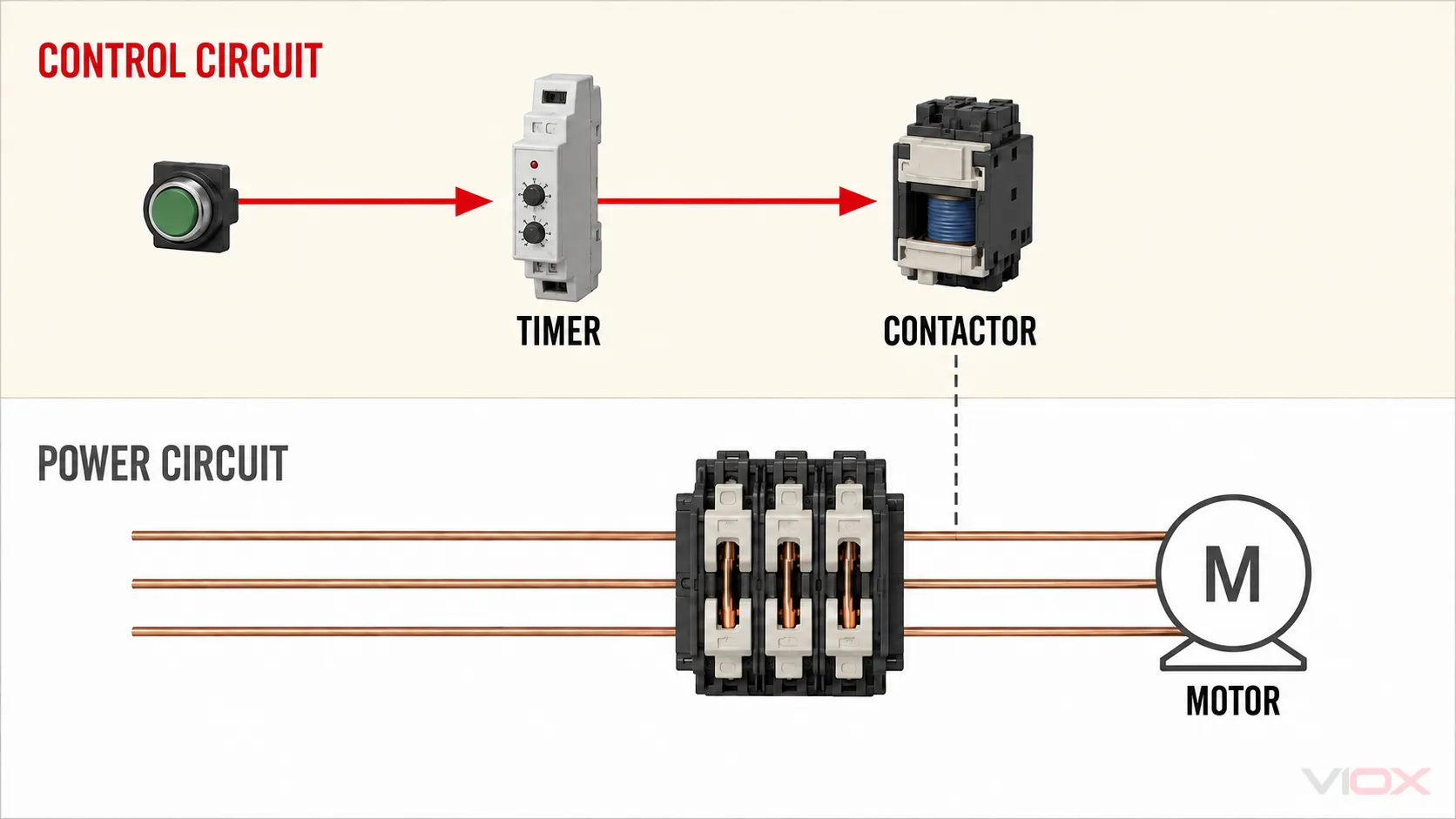
The Circuit Boundary to Establish First
A motor starter normally contains two electrically different paths:
| Path | What it carries | Typical devices in the path | Timer relay’s role |
|---|---|---|---|
| Motor power circuit | Motor load current | Disconnecting and protective devices, contactor main poles, overload current path, motor | None; do not place a general-purpose timer contact here |
| Starter control circuit | The command and contactor-coil current | Stop device, overload auxiliary contact, start command, auxiliary holding contact, timer, contactor coil | Delays the command that energizes the contactor coil |
The timer output is therefore a control contact. It does not replace the contactor, overload protection, branch-circuit protection, disconnecting means, safety functions, or the machine control system.
If you are still identifying the timer’s supply and contact terminals, use the 8-pin, 11-pin, and DIN-rail time relay wiring guide before applying the motor-starter sequence below.
Documents and Ratings You Need Before Wiring
Do not begin from a terminal number copied from another relay. Collect the current documents for the installed equipment:
- the timer relay connection diagram and timing chart;
- the contactor or starter control schematic;
- the contactor-coil voltage, frequency where applicable, and coil consumption or inrush/holding data;
- the timer output-contact rating for the relevant control load;
- the overload relay auxiliary-contact diagram and reset behavior;
- the machine or panel schematic, including safety and permissive circuits;
- the applicable installation rules and the assembly manufacturer’s conductor, protection, and terminal-torque instructions.
Use the checklist below to decide whether the components can be connected directly.
| Check | What must match | If it does not match |
|---|---|---|
| Timer supply | Available control voltage and the timer’s declared supply range, including AC/DC and frequency | Use the correct timer version or a properly designed control supply |
| Timer start method | Supply-start or separate control-input behavior must match the intended command | Choose the correct function or revise the control logic |
| Contactor coil | Coil voltage and type must match the control circuit | Replace the coil/contactor or provide the correct control voltage |
| Timer output duty | Output contact must be suitable for the contactor-coil switching duty, not merely a quoted resistive current | Use a suitable output or an interposing relay/contactor interface |
| Contact arrangement | The required timed normally open contact must be available | Select the correct output configuration |
| Reset behavior | Timer and starter must return to the intended state after Stop, overload trip, or power interruption | Change the function or circuit before commissioning |
A contactor coil is an inductive control load. A large resistive-load number on the timer face is not enough by itself to prove suitability. Use the model documentation’s control-load rating or utilization category where one is provided. The separate guide to time relay contacts on inductive loads explains why this distinction matters.
If the available control supply has not been fixed, use the 12 V, 24 V, 120 V, and 230 V timer-relay voltage selection guide before choosing a timer version.
Choose the Required Operating Sequence
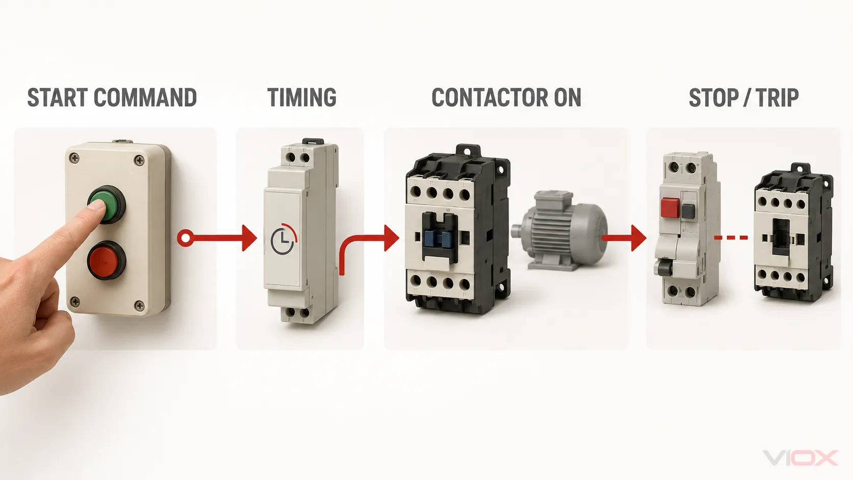
Write the sequence in states before drawing conductors. For a basic delayed start, the intended sequence is:
- Idle: the contactor coil is de-energized and the motor is stopped.
- Start command: the timer receives its start condition, but the contactor remains de-energized.
- Timing: the command remains valid for the complete delay.
- Timed run: the timer’s timed normally open output closes and energizes the contactor coil.
- Stop or trip: opening the stop path or overload auxiliary contact de-energizes the contactor and resets the timer as required by its function.
This is an on-delay task. Do not substitute an off-delay mode merely because the desired action involves a time setting. Review the on-delay versus off-delay timing diagrams if the reset and output states are not clear.
Decide Between Three-Wire and Maintained-Command Control
Three-wire control normally uses a momentary Start device, a normally closed Stop path, and an auxiliary contact that maintains the command after Start is released. A maintained-command circuit instead keeps a run signal present through a maintained switch, pressure switch, controller output, or another control device.
These command types are not interchangeable. In particular, determine what the machine must do after control power returns. An automatic restart may be unacceptable for equipment that people can access. Preserve the original machine’s restart prevention, safety functions, and risk-control design.
Conceptual Three-Wire On-Delay Circuit
The following is a functional ladder concept, not a construction drawing. KT is the timer relay and K1 is the motor contactor. The exact symbols, terminal numbers, control voltage, protection, neutral/return arrangement, and safety devices come from the approved project schematic.
CONTROL SUPPLY                                             RETURN

Rung 1:  ──[ STOP NC ]──[ OL NC ]──┬──[ START NO ]──┬──( KT timer )──
                                    │                │
                                    └──[ K1 AUX NO ]─┘

Rung 2:  ──[ STOP NC ]──[ OL NC ]────[ KT TIMED NO ]──( K1 coil )──
The sequence is:
- Pressing Start energizes
KT, which begins the on-delay period. - When the delay expires,
KT TIMED NOcloses and energizes theK1contactor coil. - The
K1 AUX NOcontact then maintains the timer command after the momentary Start device is released. - Pressing Stop or tripping the overload opens the upstream safety chain, removing the command from both rungs so
K1drops out andKTresets according to its documented function.
This arrangement is only one valid functional pattern. A timer with a separate supply and control input may require continuous power at its supply terminals and a separate start signal. A PLC-controlled starter may use the timer’s output as an input rather than switching the contactor coil directly. Follow the exact timer timing chart and the approved machine schematic.
Step-by-Step Wiring Procedure
1. Isolate and Prove the Circuit De-Energized
Identify every power source that can energize the panel, including separate control supplies and externally powered controller signals. Isolate them under the site’s procedure and verify the de-energized state. Stop if the equipment cannot be made safe or the circuit cannot be positively identified.
2. Mark the Existing Power and Control Paths
Trace the contactor main poles and motor conductors separately from the contactor-coil circuit. Confirm that the proposed timer contact will act only in the control circuit. If the existing drawing and physical wiring do not agree, resolve the discrepancy before changing the circuit.
3. Confirm the Timer Function and Start Method
Using the timer’s timing chart, select on-delay operation and identify:
- supply terminals;
- any separate control or trigger input;
- the timed output common, normally open, and normally closed contacts;
- the state of each output before, during, and after timing;
- reset behavior when the start signal or supply is removed.
Labels such as A1/A2 and changeover numbers such as 15/16/18 are common conventions, not universal instructions. Connect only from the exact model diagram.
4. Verify Direct Coil Switching or Specify an Interface
Compare the contactor-coil duty with the timer output rating. If the timer documentation does not establish that the output can switch that coil under the actual control voltage and duty, use a properly selected interposing device or another approved interface. Do not infer suitability from a resistive-load rating alone.
5. Wire the Stop and Overload Chain First
Keep the normally closed Stop function and overload relay’s normally closed trip contact in the control path ahead of the timer and contactor-coil branches. Existing emergency-stop and safety-related devices must remain in their engineered safety circuit; this article does not redesign that circuit.
Before proceeding, verify continuity or state indication according to the project test method:
- the stop path is closed in its normal state and opens when operated;
- the overload auxiliary contact is closed when reset and opens when the overload trips;
- neither function is bridged by the timer connection.
6. Wire the Timer Supply or Trigger Path
Connect the timer exactly as its diagram requires:
- For a supply-start timer, the control command applies and removes the timer supply.
- For a separately triggered timer, its power supply may remain present while a dedicated control input starts or resets timing.
Maintain the required polarity for DC equipment and the specified line/return arrangement for AC equipment. Stop if the timer function chart does not show the intended behavior.
7. Wire the Timed Output to the Contactor-Coil Path
Place the timer’s timed normally open output in the path that energizes K1, or route it to the approved controller/interface input. The contactor coil’s other side returns through the control circuit as shown on the project schematic.
Do not move the overload contact out of the trip path. Do not use the timer contact as the motor’s main switching device.
8. Complete the Holding Logic Where Required
For three-wire control, connect the correct contactor auxiliary normally open contact so it maintains the timer command after the contactor has energized. Check that Stop and overload operation still remove the maintained command.
For a maintained-command system, do not add a seal-in branch unless the approved control philosophy requires it. The external maintained signal may already provide the hold condition.
9. Inspect Before Re-Energizing
Check the completed work against both the approved schematic and the physical terminal labels:
- correct conductor destinations and identification;
- no loose strands, unintended bridges, or exposed copper;
- polarity and control voltage correct;
- protective and overload functions retained;
- timer mode and range set to a conservative initial value suitable for the process;
- terminals tightened to the equipment manufacturer’s instructions;
- covers, barriers, and wiring ducts restored.
If any connection depends on an assumed terminal number, stop and obtain the correct document.
Commission the Delayed-Start Sequence
Initial functional checks should be performed in the safest test state permitted by the machine procedure—for example, with the driven process isolated or otherwise prevented from creating motion where the approved commissioning plan allows it. Do not improvise a motor-disconnected test if that would defeat monitoring or protection built into the system.
| Test state | Expected timer state | Expected contactor/motor state | Stop condition |
|---|---|---|---|
| Control power applied, no start command | Reset; timed output in its normal state | Contactor de-energized; motor stopped | Contactor energizes unexpectedly |
| Start command applied | Timing indication follows the model chart | Contactor remains de-energized during the set delay | Contactor energizes immediately when a delay is required |
| Delay completed | Timed normally open output changes state | Contactor energizes and the motor starts if all permissives are healthy | Chattering, abnormal sound, unstable voltage, or unexpected sequence |
| Start device released in three-wire control | Timer command remains held by the intended auxiliary path | Contactor remains energized | Circuit drops out when it should seal in, or cannot be stopped |
| Stop operated | Timer resets or changes state as documented | Contactor drops out without intentional delay | Contactor remains energized |
| Overload test/trip performed under the approved procedure | Timer command is removed or inhibited as designed | Contactor drops out and restart is prevented until the required reset | Timer wiring bypasses the overload trip path |
| Control power interrupted and restored | Returns to the documented safe reset/restart state | No unexpected restart | Motor starts without the required new command |
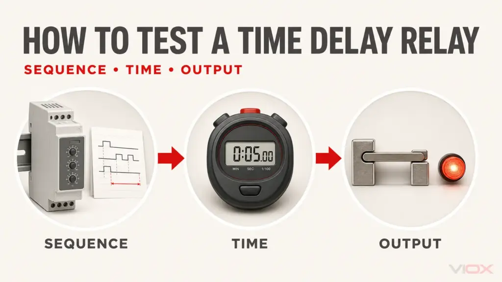
Measure the actual delay from the defined start event to contactor pickup and compare it with the process requirement and timer tolerance stated by the manufacturer. If the measured sequence differs from the timing chart, isolate the system before changing connections or settings. The separate time delay relay bench-test procedure can help determine whether the timer itself operates correctly outside the installed control logic.
If the Circuit Does Not Work as Intended
| Symptom | Check first | What the result may mean | Next action |
|---|---|---|---|
| Timer never starts | Voltage or trigger state at the timer, measured according to the exact diagram | Open Stop/overload path, wrong supply, wrong trigger logic, or wiring error | Isolate and trace the command path |
| Timer indicates timing but contactor never energizes | Timed output state and voltage at the contactor coil | Wrong output contact, unsuitable interface, open coil path, or coil mismatch | Compare both device diagrams; test the output and coil separately under an approved procedure |
| Contactor energizes immediately | Selected timing mode and use of instantaneous versus timed contact | Wrong function or wrong output contact | Isolate, correct the function/contact, and recommission |
| Contactor drops out when Start is released | Holding-contact state and seal-in path | Missing, incorrect, or unavailable auxiliary hold contact | Correct the three-wire holding logic or use the approved maintained command |
| Stop does not remove the run command | Location of Stop contact relative to both timer and coil branches | Unsafe bypass or unintended alternate feed | Isolate immediately and restore the stop path before further testing |
| Contactor chatters or timer resets | Control voltage at the timer and coil during pickup | Supply drop, loose connection, incorrect coil, output-duty problem, or unstable command | Stop testing; correct the supply/interface issue before repeating |
| Motor restarts after power restoration | Command type, timer memory/reset behavior, and holding logic | Maintained signal or unsuitable restart design | Revise the approved control philosophy; do not rely on timer delay alone for restart prevention |
Where This Guide Stops
This procedure covers one contactor controlled by a time relay for a delayed-start sequence. It does not design reversing, plugging, jogging, multi-speed, safety-rated, soft-starter, variable-frequency drive, or star-delta systems. A star-delta starter requires coordinated main, star, and delta contactors plus electrical/mechanical interlocking and transition logic; use the dedicated star-delta starter wiring and selection guide for that separate task.
For product evaluation after the control sequence and ratings are known, compare the available DIN-rail timer relay range by supply voltage, timing function, time range, output arrangement, and documented contact duty.
Source References
- ABB, Electronic Relays and Controls Catalog — Time Relays: function diagrams, connection diagrams, and application circuits for electronic timers.
- Rockwell Automation, Bulletin 700-HR Plug-in Timing Relays: model-specific timing charts and wiring diagrams.
- Schneider Electric, Motor Control Solutions for the North American Market: motor-starter construction, control circuits, and wiring-document context.
- Schneider Electric, How do I operate a star delta starter with 2 wire control?: explanation of two-wire and three-wire command behavior and restart considerations.