Quick Answer: What Is a Time Delay Relay?
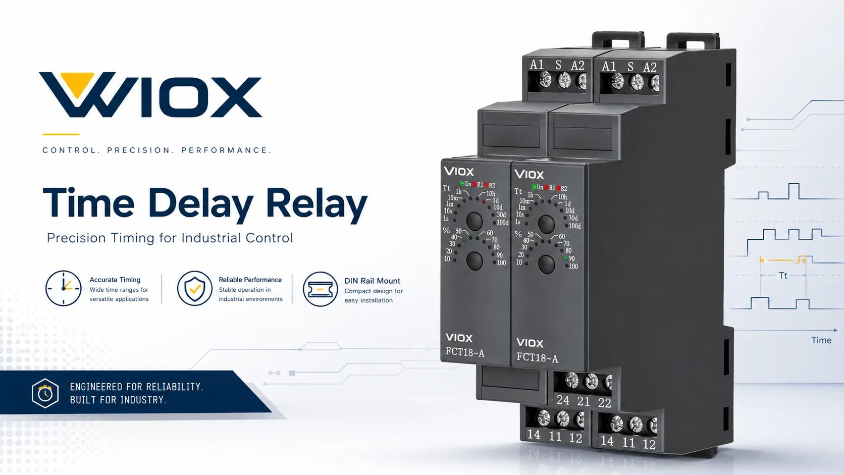
A مرحل التأخير الزمني is a control relay that changes its output contact state after a preset time condition. Instead of switching immediately like a basic relay, it delays turn-on, delays turn-off, creates a timed pulse, or repeats an on/off cycle depending on the selected timing function.
In industrial control panels, time delay relays are commonly used for:
- motor startup sequencing;
- compressor anti-short-cycle protection;
- cooling fan post-run;
- pump run-on;
- star-delta transition timing;
- alarm delay;
- conveyor and machine sequence control.
النقطة الأساسية بسيطة: a normal relay switches when the input changes; a time delay relay switches when the input condition and the preset time requirement are both satisfied.
Time Delay Relay Functions at a Glance
| الوظيفة | Output behavior | الأسماء الشائعة | التطبيق النموذجي |
|---|---|---|---|
| تأخير عند التشغيل | Output turns ON after the preset delay | Delay on make, timer on delay, TON | Motor startup sequence, compressor restart delay |
| تأخير الإيقاف | Output stays ON after input is removed | Delay on break, timer off delay, TOF | Fan post-run, pump run-on, delayed shutdown |
| فاصلة | Output turns ON for a preset time after trigger | One-shot, pulse timer | Dosing, alarm pulse, signal extension |
| Repeat cycle | Output alternates ON and OFF | Flasher, cyclic timer | Periodic control, flashing signal |
| Star-delta timing | يتحكم في توقيت الانتقال | مؤقت التوصيل النجمي-المثلث (Star-delta) | Motor starter transition |
| متعدد الوظائف | Multiple timing modes in one device | Universal timer relay | OEM panels and flexible control cabinets |
For the detailed difference between on-delay and off-delay operation, see VIOX’s On Delay vs Off Delay Timer دليلنا.
How Does a Time Delay Relay Work?
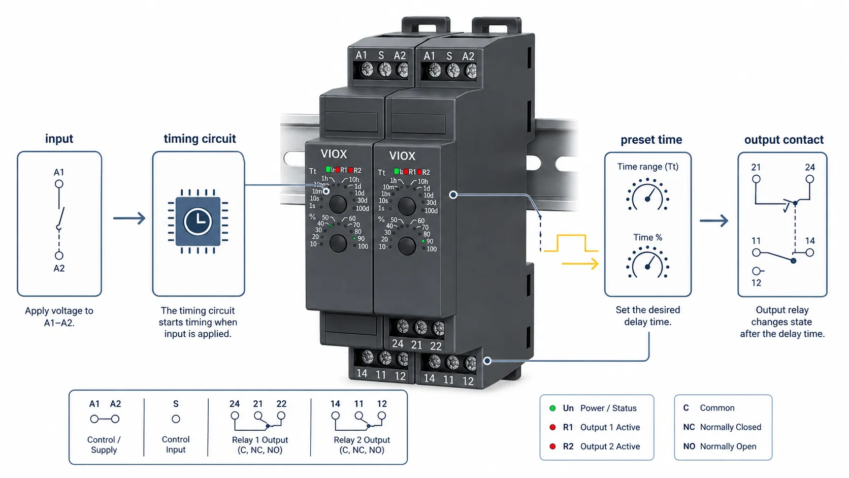
A time delay relay normally includes:
- a power supply or coil input;
- a trigger input on some models;
- an internal timing circuit;
- محدد نطاق التوقيت؛;
- one or more output contacts;
- a timing diagram printed in the datasheet or on the product body.
تسلسل التشغيل الأساسي هو:
- The relay receives supply voltage or a trigger signal.
- The internal timing circuit starts or resets according to the selected function.
- The relay counts the preset time.
- The output contact changes state when the timing condition is satisfied.
- The output resets when the input condition or timing cycle ends.
The exact behavior depends on the function. This is why the timing diagram is more reliable than the product name alone.
Video: Time Delay Relays Explained
Time Delay Relay Working Principle
The working principle is based on separating input condition, elapsed timeو output state.
| Control element | المعنى |
|---|---|
| Input or coil | Starts, holds, or resets the timing function |
| الوقت المحدد مسبقًا | The selected delay value |
| دائرة التوقيت | Measures elapsed time |
| جهة اتصال الإخراج | Opens or closes after the timing condition is met |
| Reset condition | Defines when the timer returns to its initial state |
Electronic time delay relays usually use solid-state timing circuits, while older electromechanical designs may use mechanical, pneumatic, or motor-driven mechanisms. For modern DIN-rail control panels, electronic multifunction timer relays are common because they provide compact size, multiple modes, and adjustable time ranges.
For engineers, the most important detail is not the knob on the front of the relay. It is the سلوك إعادة الضبط hidden in the timing diagram. Some relays reset immediately when supply power is removed. Others keep timing only while the control supply is present. A smaller group of true power-off delay timers can hold the output after supply removal because the timing energy is stored internally or maintained by a mechanical latch mechanism.
On Delay Time Relay
أن on delay relay delays output activation. When the input turns ON, the relay starts timing. If the input remains ON until the preset time expires, the output changes state.
Example logic:
Input ON -> timing starts -> preset time reached -> output ON
Input OFF -> output resets
Use on delay when a load should الانتظار قبل البدء.
التطبيقات الشائعة:
- starting motors one by one;
- delaying compressor restart;
- preventing short false signals from starting equipment;
- delaying a contactor coil after control power returns;
- sequencing conveyors or pumps.
Off Delay Time Relay
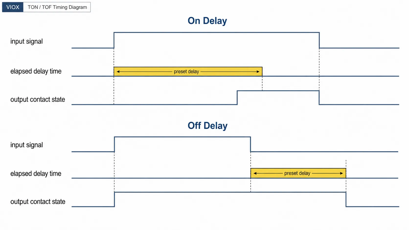
أن off delay relay delays output deactivation. The output turns ON immediately when the input turns ON. When the input turns OFF, the relay keeps the output ON for the preset time, then turns it OFF.
Example logic:
Input ON -> output ON immediately
Input OFF -> timing starts -> preset time reached -> output OFF
Use off delay when a load should الاستمرار في العمل بعد إزالة أمر التشغيل.
التطبيقات الشائعة:
- motor cooling fan post-run;
- pump run-on after a level switch opens;
- exhaust fan purge;
- lighting delay after a switch is released;
- delayed shutdown of auxiliary circuits.
Other Types of Time Delay Relays
مرحل مؤقت الفاصل الزمني
An interval timer turns the output ON for a preset period after a trigger signal. It is useful when a control system needs a timed pulse rather than a sustained output.
Typical uses include dosing pumps, alarm buzzers, signal extension, and short process actions.
Repeat Cycle Timer Relay
A repeat cycle timer alternates the output between ON and OFF according to selected timing values. Some models allow equal ON/OFF times, while others allow independent ON and OFF time settings.
Typical uses include flashing signals, lubrication intervals, periodic ventilation, and simple cyclic control.
Star-Delta Timer Relay
A star-delta timer is used in motor starting circuits. It controls the delay between star connection and delta connection in a star-delta starter. This function should be selected based on the motor starter design and motor starting behavior, not only by the time range.
Multifunction Time Delay Relay
A multifunction time delay relay provides several timing modes in one device. It is useful for distributors, OEMs, and panel builders who want one stock item to cover multiple timing applications.
For a dedicated comparison, see VIOX’s guide to multifunction timer relay vs single-function timer relay.
Time Delay Relay Wiring Diagram Basics
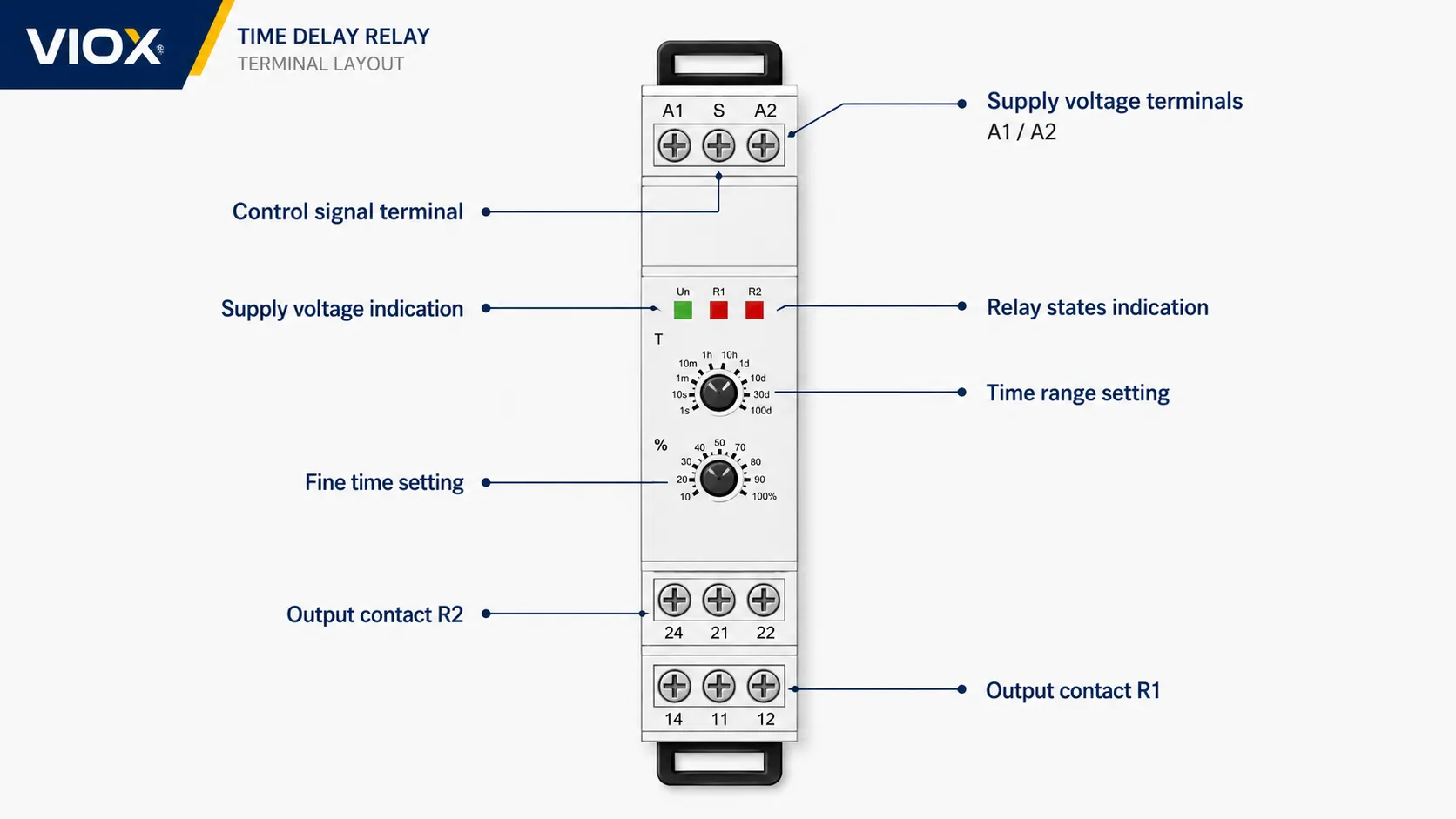
Most industrial time delay relays include supply terminals and output contacts. A common terminal style is:
| المحطة الطرفية | المعنى النموذجي |
|---|---|
| A1 / A2 | Supply or coil terminals |
| 15 | Common contact |
| 16 | نقطة تلامس مغلقة طبيعياً (NC) |
| 18 | نقطة تلامس مفتوحة طبيعياً (NO) |
| 25 / 26 / 28 | Second changeover contact on some models |
| TR / S / B1 | Trigger or control input on some models |
The exact terminal names vary by manufacturer and model. Always use the datasheet wiring diagram for the specific relay.
Typical Control-Circuit Use
In a motor control panel, the time delay relay output often controls a contactor coil:
Control supply -> time delay relay output contact -> contactor coil -> return
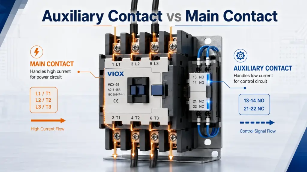
The time delay relay provides timing logic. The contactor switches the motor power circuit. Do not use a small timer relay contact as the main motor switching contact.
For more wiring examples, see VIOX’s دليل مخطط توصيل مرحل التأخير الزمني الخاص بـ VIOX.
Time Delay Relay Symbols and Contact Logic
Time delay relay symbols depend on the drawing standard, project legend, and manufacturer documentation. Do not rely on a single graphic symbol without checking the schematic legend.
Common contact behavior terms include:
| مصطلح | المعنى |
|---|---|
| Timed NO contact | Normally open contact with timed operation |
| Timed NC contact | Normally closed contact with timed operation |
| NOTC | Normally open, timed closed |
| NCTO | Normally closed, timed open |
| Delay-on-make | Output changes after input is applied and time expires |
| Delay-on-break | Output remains active after input is removed, then releases |
For field troubleshooting, the timing diagram is usually more useful than the symbol alone. It shows exactly when the input changes, when timing begins, and when the output contact changes state.
Time Delay Relay vs Timer Relay vs Timer Switch
These terms are often mixed in search and procurement, but they are not always identical.
| مصطلح | المعنى العملي |
|---|---|
| Time delay relay | Relay with built-in delay or timing function |
| مرحل التوقيت (Timer relay) | Common synonym for time delay relay |
| مرحل التوقيت | Common industrial term for timer relay |
| مفتاح مؤقت | Usually a clock or schedule-based switching device |
| Contactor timer | Often refers to a timer relay controlling a contactor coil |
If the circuit timing depends on an input signal, you are usually looking for a time delay relay. If the circuit switches by time of day or weekly schedule, you are usually looking for a timer switch.
Motor Time Delay Relay Applications
Time delay relays are widely used in motor control, but the function must match the motor problem.
| Motor application | Recommended timing function | لماذا |
|---|---|---|
| Start motors one by one | تأخير عند التشغيل | يقلل من الطلب المتزامن عند البدء |
| يمنع التشغيل المتكرر القصير للضاغط | تأخير عند التشغيل | يمنع إعادة التشغيل الفوري |
| Keep fan running after motor stops | تأخير الإيقاف | إزالة الحرارة المتبقية |
| Keep pump running briefly after level signal clears | تأخير الإيقاف | Clears remaining liquid |
| Star-delta starter transition | مؤقت التوصيل النجمي-المثلث (Star-delta) | Controls transition from star to delta |
| Alarm delay before trip signal | On delay or interval | Avoids nuisance alarm from brief transients |
A time delay relay should not hide an electrical or mechanical fault. If a motor trips repeatedly, check motor current, overload setting, voltage condition, contactor condition, bearing load, and mechanical jam before adding more delay.
How to Choose a Time Delay Relay
Use this checklist before ordering:
| عنصر الاختيار | ما يجب التحقق منه |
|---|---|
| وظيفة التوقيت | On delay, off delay, interval, repeat cycle, star-delta, multifunction |
| نطاق التوقيت | Minimum and maximum time setting |
| جهد الإمداد | AC or DC control voltage |
| جهة اتصال الإخراج | أحادي القطب مزدوج الرمي (SPDT)، ثنائي القطب مزدوج الرمي (DPDT)، خرج مرحل، خرج ترانزستور |
| تقييم الاتصال | Resistive and inductive load capability |
| نوع الحمل | Contactor coil, solenoid, PLC input, lamp, fan, pump |
| سلوك إعادة الضبط | What happens when input or supply power is removed |
| Trigger input | Whether a separate trigger terminal is required |
| التركيب | DIN rail, socket, panel, PCB |
| التوثيق | Wiring diagram, timing diagram, standard references |
For a broader selection framework, use VIOX’s لاختيار مرحل التوقيت (timer relay). For product evaluation, review VIOX توقيت التتابع الخيارات.
Contact Ratings: AC-15 and DC-13
The output contact is a common failure point when a time delay relay switches an inductive load. Contactor coils, solenoids, and valves can stress contacts more than simple resistive loads.
For control circuit devices, categories such as AC-15 و DC-13 under IEC 60947-5-1 are commonly used for electromagnetic control loads.
| نوع الحمل | ما يجب التحقق منه |
|---|---|
| حمل مقاوم | الجهد والتيار المقدر |
| AC contactor coil | AC-15 or equivalent inductive rating |
| DC solenoid | DC-13 rating and arc suppression |
| Motor power circuit | Use a contactor or starter instead of timer contact |
| PLC input | Minimum load, leakage current, input voltage |
If the relay contact is underrated, symptoms may include welded contacts, intermittent output, contact burning, or shortened relay life.
Field Note: When the Timer Is Blamed for a Load Problem
A common packaging-line fault is a timer relay that appears to “fail” every few weeks. In many cases, the timer is not failing because of its timing circuit. The real issue is that the relay contact is switching a small inductive load directly, such as a contactor coil or solenoid valve, without checking the AC-15/DC-13 rating or adding proper surge suppression.
The usual symptom is not a wrong delay setting. It is a burnt or welded output contact. In this situation, the practical fix is to separate the timing function from the load switching function: use the time delay relay to control a correctly rated contactor or interface relay, and add an RC snubber, varistor, diode, or other suppression device where the circuit design requires it.
How to Test a Time Delay Relay
Testing depends on the relay type, but a practical field check usually includes:
Video: How to Wire a Timer Relay
| Test step | ما يجب التحقق منه |
|---|---|
| الفحص البصري | Burn marks, cracked housing, loose terminals, damaged dial |
| Supply voltage check | Correct voltage at A1/A2 or supply terminals |
| Timing function check | Output changes according to the timing diagram |
| Contact continuity | NO and NC contacts change state correctly |
| Timing repeatability | Delay is consistent over several cycles |
| Load check | Output behaves correctly under the actual control load |
Do not test a timer relay in a live industrial panel unless you are qualified and the site procedure allows it. Isolate the circuit where required, label conductors before removal, and use the manufacturer’s datasheet for terminal identification.
Common Time Delay Relay Problems
| الأعراض | Possible cause | ما يجب التحقق منه |
|---|---|---|
| Relay does not power up | Wrong supply voltage, open circuit, blown control fuse | A1/A2 voltage, fuse, wiring |
| Output never changes | Wrong function selected, no trigger input, failed relay | Function mode, trigger terminal, timing diagram |
| Delay is inconsistent | Unstable supply, electrical noise, aging component, wrong range | Supply quality, setting range, repeated timing test |
| Output chatters | Low voltage, loose terminal, contactor coil interference | Control voltage, terminals, suppression |
| Contacts weld or burn | Load exceeds contact rating, inductive load not suppressed | AC-15/DC-13 rating, contactor coil, snubber/diode |
| Machine starts too early | Wrong timer function or incorrect contact used | NO/NC contact, timing diagram, wiring |
أخطاء الاختيار الشائعة
Mistake 1: Choosing Only by Time Range
A relay with the correct time range can still be wrong if the timing function, supply voltage, contact rating, or reset behavior does not match the circuit.
Mistake 2: Confusing On Delay and Off Delay
On delay waits before energizing the output. Off delay holds the output after input removal. These functions solve opposite problems.
Mistake 3: Using the Timer Contact as a Motor Power Contact
A timer relay contact is usually a control contact. Use it to control a contactor coil, PLC input, or alarm circuit. Use a contactor or motor starter for motor power switching.
Mistake 4: Ignoring Power-Off Behavior
Some off-delay relays still need control power while timing. They delay release after a trigger input changes state, but the timing circuit itself still depends on an energized supply.
If the output must remain active after total power loss, specify a مؤقت تأخير إيقاف التشغيل الحقيقي (true power-off delay timer) and verify the datasheet. These devices usually depend on an internal energy-storage circuit, such as a charged capacitor, or a mechanical latch arrangement that can maintain the output for a limited period after supply removal. That difference matters in fan purge, brake release, alarm hold, and safe shutdown circuits.
Mistake 5: Replacing a Relay Without Checking the Timing Diagram
Two relays can share the same pin layout but have different timing functions. Always compare the timing diagram before replacement.
الأسئلة الشائعة
What is the purpose of a time delay relay?
A time delay relay controls when a circuit changes state. It is used when equipment should start later, stop later, run for a fixed interval, or follow a repeated timing cycle.
كيف يعمل مرحل التأخير الزمني؟
It receives a supply or trigger signal, starts an internal timing circuit, and changes its output contact when the preset timing condition is reached. The exact sequence depends on the selected function.
What is the difference between on-delay and off-delay relay?
An on-delay relay delays output turn-on after the input is applied. An off-delay relay turns on immediately, then delays output turn-off after the input is removed.
What do A1/A2 and 15/16/18 mean on a time delay relay?
A1 and A2 are commonly used for the relay supply or coil. In many changeover contact layouts, 15 is common, 16 is normally closed, and 18 is normally open. Always confirm the exact model datasheet.
Can a time delay relay control a motor directly?
Usually no. A time delay relay is normally used in the control circuit. Use a properly rated contactor or motor starter to switch the motor power circuit.
How do I test a time delay relay with a multimeter?
Check the correct supply voltage at the relay, then use continuity or voltage measurement to confirm that the output contact changes state according to the timing diagram. Repeat the test several times to confirm timing consistency.
What causes a time delay relay to chatter?
Common causes include low control voltage, loose wiring, unstable trigger input, electromagnetic interference, contactor coil feedback, or an incorrect load connection.
What is the difference between a time delay relay and a timer switch?
A time delay relay reacts to an input event and changes output after a delay. A timer switch usually follows clock time, daily schedules, weekly schedules, or astronomical time.
Which time delay relay function is used for motor starting?
On delay is commonly used for delayed motor starting and motor sequencing. Star-delta motor starters use a dedicated transition timing function.
What contact rating should I check for contactor coils?
Check the relay’s inductive control rating, such as AC-15 for AC contactor coils or DC-13 for DC coils where applicable. Do not rely only on the resistive load rating.
الختام
A time delay relay is more than a relay with a time knob. The correct device must match the timing function, voltage, contact rating, wiring diagram, reset behavior, and load type.
الاستخدام تأخير التشغيل (On Delay) when the output should wait before turning on. Use تأخير الإيقاف (Off Delay) when the output should stay on after the command is removed. Use interval أو repeat cycle functions when the output must pulse or cycle. For motors, pumps, fans, compressors, and control panels, always confirm the timing diagram and contact rating before installation or replacement.