On this page
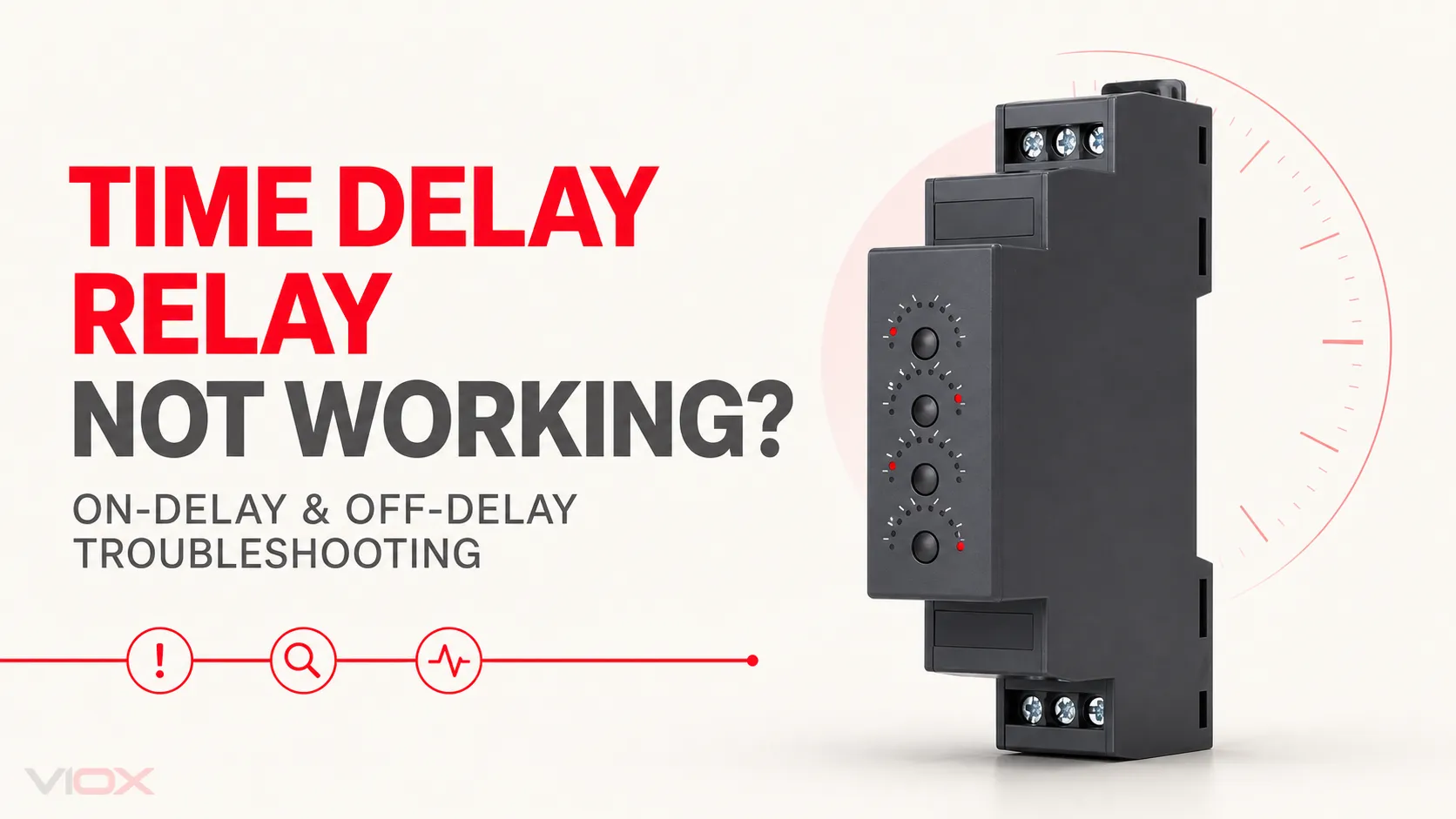
If a DIN-rail time delay relay is not working, check five points in order: supply, trigger, selected function, output contact, and load circuit. This separates an actual relay failure from incorrect on-delay/off-delay settings, control-signal problems, and output wiring faults.
Do not replace the relay only because the load does not operate. A powered indicator does not prove that timing has started, and an audible click does not prove that the output contact is correctly wired or able to switch the load.
This guide is limited to DIN-rail time delay relays operating in on-delay or off-delay mode. Exact terminal numbers and control behavior vary by model, so use the diagram and timing chart supplied with the relay as the final reference.
Key Takeaways
- Verify the rated supply directly at the relay terminals before testing its timing function.
- Determine whether the relay is set to on-delay or off-delay and identify the event that starts timing.
- Check whether the application uses a power-triggered or separately triggered timer.
- Many time delay relays have dry output contacts; the contact does not generate voltage by itself.
- A click shows that the internal mechanism moved, but it does not prove that the load circuit is healthy.
- If an off-delay relay releases immediately, check whether it still requires continuous operating power.
- Replace the relay only after the external supply, trigger, wiring, and load have been verified.
Safety: Isolate the circuit and verify the absence of voltage before changing wiring or performing resistance and continuity tests. Live measurements should be carried out only by qualified personnel using suitable instruments and the required site procedure. Never use resistance or continuity mode on an energized circuit.
Symptom-to-Cause Troubleshooting Table
| Symptom | Likely cause | What to test | Corrective action |
|---|---|---|---|
| No power indicator or response | Missing supply, wrong voltage or AC/DC type, incorrect supply terminals, loose terminal | Measure at the relay’s actual supply terminals and compare with its rating | Restore the correct supply, correct the connection, or replace the relay if the specified supply is present and it remains inactive |
| On-delay timer powers up but does not begin timing | Start input missing, wrong trigger logic, reset active, wrong function selected | Compare the supply and trigger sequence with the model timing diagram | Correct the input signal, reset condition, or function selector |
| On-delay completes but the load remains off | Dry contact is not fed, wrong COM/NO terminal, open load circuit, failed contact | Test the isolated contact state, then trace the load voltage | Feed COM correctly, correct the output wiring, repair the load circuit, or replace a failed relay |
| Off-delay output turns off immediately | Relay supply was removed, wrong off-delay mode, trigger wired incorrectly | Check whether the model requires continuous supply during the delay | Maintain the required supply, correct the trigger wiring, or select the correct off-delay architecture |
| Off-delay output does not release | Trigger remains active, wrong COM/NC terminal, parallel feed, contact stuck | Verify the trigger state and test the isolated output contact | Correct the control logic or wiring; replace the relay if the contact remains stuck |
| Delay is too short, too long, or inconsistent | Wrong range, wrong function, unstable supply or trigger, setting change not accepted until reset | Observe repeated cycles while monitoring supply, trigger, range, and dial setting | Select the correct range/function, stabilize the control signal, and reset as required by the manufacturer |
| Relay indicates output or clicks, but no voltage reaches the load | Dry contact has no source at COM, wrong contact selected, downstream circuit open | Confirm the source at COM and measure through the switched circuit | Correct the source and terminal selection or repair the downstream circuit |
First Confirm the Intended Sequence
Before taking measurements, write down what the circuit should do.
Expected on-delay sequence
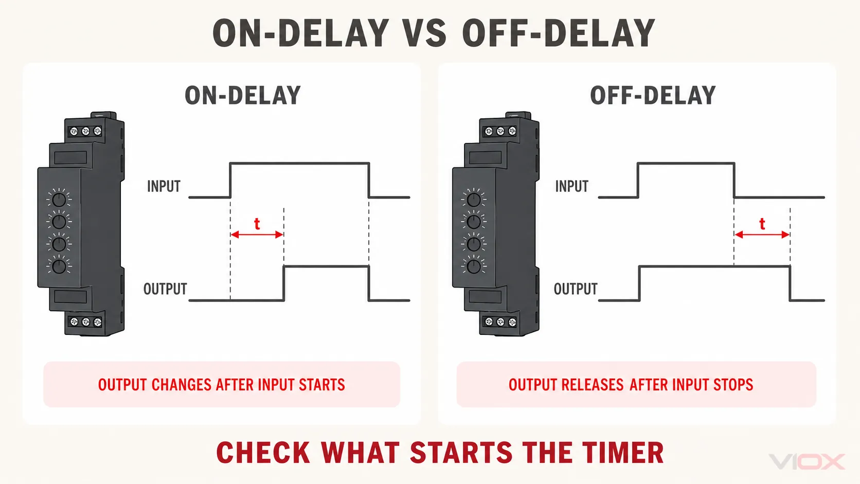
In a typical on-delay sequence, the supply or start signal becomes active, the relay begins timing, and the timed output changes state only after the set delay has elapsed. When the initiating condition is removed, the output normally returns according to the model’s documented reset behavior.
If the trigger disappears before the delay finishes, many on-delay relays reset rather than completing the cycle. Therefore, a short or unstable control signal can look like a defective timer.
Expected off-delay sequence
In a typical off-delay sequence, the output operates when the initiating signal is present and remains operated for the set delay after that signal is removed. However, not every off-delay relay handles power removal in the same way.
Some models need continuous operating power and use a separate trigger input. Other designs are specifically intended to time after their supply is removed. If a continuously powered off-delay timer loses its own supply, it may release or reset immediately instead of completing the delay.
If the expected sequence is unclear, review the difference between on-delay and off-delay timers before troubleshooting the hardware.
Five Checks That Locate Most Time Delay Relay Faults
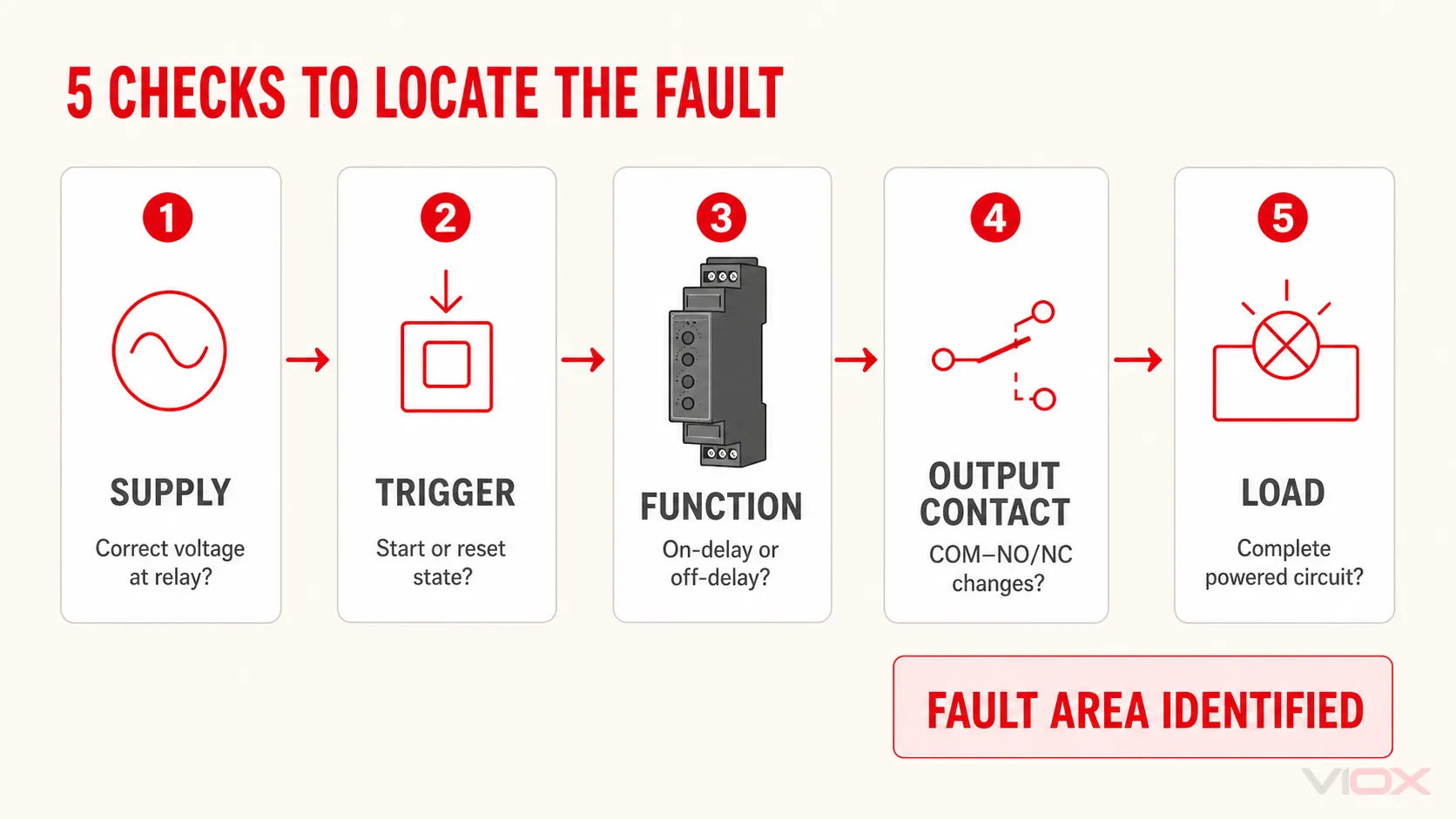
1. Is the correct supply present at the relay?
Read the rated supply and AC/DC requirement from the exact model. Then measure directly across the designated supply terminals.
Do not rely only on a measurement at the control transformer, power supply, or upstream terminal block. An open fuse, loose conductor, control contact, or terminal fault can prevent the supply from reaching the relay.
If the specified supply is stable at the correct terminals but the DIN-rail relay shows no response, isolate the circuit and inspect the terminal connection and enclosure for discoloration, cracking, odor, or other damage. The relay may require replacement, but the cause of any damage must also be corrected.
2. Is the start or trigger input in the correct state?
Some DIN-rail time delay relays start timing when their operating supply is applied. Others remain powered and require a separate control input. That input may expect switched voltage or a contact signal depending on the model.
Compare the measured sequence with the manufacturer’s timing chart:
- Does the start signal reach the correct input?
- Is the signal referenced to the correct common terminal?
- Does it remain stable long enough for the on-delay cycle to finish?
- Is a reset input active?
- Does a sensor, programmable logic controller output, or control contact change state unexpectedly?
A measurement taken only before or after the machine cycle can miss a brief dropout. Observe the supply and trigger while the fault occurs.
3. Is the correct on-delay or off-delay function selected?
A multifunction time delay relay can be electrically healthy but behave incorrectly because the wrong function is selected. Confirm the function code against the legend and manual rather than assuming the symbol’s meaning.
Also verify the time range and multiplier. A dial position has meaning only in combination with the selected seconds, minutes, hours, or range scale.
Some electronic timers apply function or range changes only after a reset or power cycle. Follow the manufacturer’s setting procedure and do not move function selectors while energized unless the documentation permits it.
4. Does the output contact actually change state?
After isolating the circuit, identify the common (COM), normally open (NO), and normally closed (NC) terminals from the exact relay diagram. Disconnect the output sufficiently to avoid false readings through the connected circuit, then compare the contact state before and after a controlled timing cycle.
This test determines whether the timing logic reaches the output stage. However, a continuity test alone does not prove that the contact performs correctly under its actual load. A damaged contact can appear acceptable at meter current but fail when switching a real coil or other load.
5. Is the load circuit complete and correctly supplied?
Many time delay relays use dry contacts. These contacts act as an isolated switch and do not create output voltage. An external source must be connected to COM before the NO or NC terminal can pass that source to the load.
If the contact changes state correctly, trace the complete load circuit:
- source to COM;
- NO or NC output to the load;
- load return or neutral;
- protection and isolating devices;
- interposing relay, contactor, or controller input;
- field wiring and the load itself.
For terminal conventions and circuit examples, refer to the time delay relay wiring diagram guide.
On-Delay Relay Not Working
On-delay timing never starts
If the relay has power but timing never begins, the most likely fault is the initiating signal or function selection.
Check whether the selected mode starts from the supply or from a separate trigger. Confirm that the trigger reaches the correct terminal and that a reset input is not holding the timer inactive. If the trigger comes from a sensor or controller output, verify that its signal type is compatible with the relay input.
If the correct and stable trigger is present but the relay does not show the documented timing response, reset the relay according to the manufacturer. Persistent failure then points more strongly to the timer itself.
On-delay keeps restarting before completion
Repeated restarts usually indicate supply interruption, trigger dropout, contact bounce, or an active reset condition. Monitor these signals during the entire delay rather than testing them only at rest.
If the problem appears when another contactor or load operates, investigate the control supply, terminal connections, switching disturbance, and control logic. Do not add suppression components with assumed values; follow the connected-device and timer manufacturers’ instructions.
On-delay completes but the output does not switch the load
Separate internal operation from external power flow:
- Confirm the output indication or timed mechanical action.
- Verify the correct COM and NO terminals.
- Confirm that the required external source reaches COM.
- Test whether COM–NO changes state after the delay.
- Trace the circuit from NO through the load and its return path.
If the contact does not change state after a valid timing cycle, the relay may be defective. If it changes state without the load but fails during operation, investigate the load duty, inrush, wiring voltage drop, and whether an appropriately rated interposing device is required.
Off-Delay Relay Not Working
Off-delay turns off immediately
First determine what was removed: the trigger signal or the relay’s own operating supply.
If the model is a continuously powered, signal-triggered off-delay timer, removing its operating supply may prevent it from completing the delay. Restore the required continuous supply and switch only the designated trigger input.
If the supply remains present, confirm that the correct off-delay function is selected and that the trigger changes state in the direction shown by the timing chart.
Off-delay does not begin timing when the trigger is removed
Check whether the trigger actually reaches its inactive state at the relay terminal. A controller output, electronic sensor, wiring error, or unintended feed may keep the input active even when the machine command appears off.
Also confirm that the selected mode is true off-delay rather than on-delay. If the relay receives the correct transition but does not begin the documented cycle, reset it according to the manual and repeat the test.
Off-delay output never releases
An output that remains active after the delay may result from:
- the trigger remaining active;
- COM–NC being used instead of COM–NO;
- a parallel feed bypassing the timer contact;
- the wrong delay range or setting;
- a welded or mechanically stuck contact.
Isolate the circuit and test the timer contact independently from parallel wiring. If the contact remains closed after the documented sequence is complete, replace the timer and check whether the connected load exceeded or was unsuitable for the contact switching duty.
When the Relay Clicks but the Load Does Not Operate
An audible click means the relay mechanism moved; it does not prove that voltage is present at the output.
The most common checks are:
- Is the contact a dry contact?
- Is the external source connected to COM?
- Is the load connected to the intended NO or NC terminal?
- Does the contact change state when isolated and tested?
- Is the downstream circuit complete?
If COM has no source, the switched terminal will have no output voltage even when the relay operates correctly. This is a wiring condition, not a timer failure.
Why the Delay Is Wrong or Unstable
Before judging timing accuracy, rule out configuration and control problems:
- wrong on-delay/off-delay mode;
- wrong time range or multiplier;
- dial or selector between positions;
- function change requiring reset or power cycle;
- unstable supply;
- repeated trigger transitions;
- application conditions outside the product specification.
Record several complete cycles while observing both the supply and trigger. If the inputs remain stable and the repeated delay falls outside the exact model’s published specification, replacement may be appropriate.
Do not apply a universal timing tolerance. Accuracy, repeatability, reset time, and setting behavior depend on the specific time delay relay.
When to Replace the Time Delay Relay
Replace the relay when the surrounding circuit has been verified and one of the following remains repeatable:
- no operation with the specified supply present;
- no timing response with the correct function and valid trigger;
- output contact does not change state after a completed timing cycle;
- contact remains mechanically stuck;
- timing falls outside the model’s published specification under valid conditions;
- visible cracking, discoloration, odor, or heat damage is present.
Before selecting a replacement, match:
| Replacement item | Required check |
|---|---|
| Supply | Voltage and AC/DC type |
| Timing function | Required on-delay, off-delay, or both |
| Trigger method | Supply-started or separately controlled |
| Timing range | Required delay and adjustment resolution |
| Output | COM/NO/NC arrangement and number of contacts |
| Load | Contact rating and suitability for the actual switching duty |
| Installation | DIN-rail format, module dimensions, and terminal layout |
| Reset behavior | Response to trigger removal and supply interruption |
The timer relay selection guide provides the next step when a replacement specification is needed.
Quick Diagnostic Checklist
- [1] Confirm the full model number and rated supply.
- [2] Measure the supply at the relay terminals.
- [3] Identify whether the mode is on-delay or off-delay.
- [4] Confirm whether timing starts from power or a separate trigger.
- [5] Monitor the trigger through the complete cycle.
- [6] Check the time range, multiplier, and setting.
- [7] Apply any manufacturer-required reset after changing settings.
- [8] Identify COM, NO, and NC from the exact diagram.
- [9] Test the isolated contact state safely.
- [10] Confirm that the dry contact receives an external source at COM.
- [11] Trace the downstream load and return path.
- [12] Replace the relay only after the external circuit is verified.
Frequently Asked Questions
Why is my on-delay relay powered but not timing?
The selected mode may require a separate start input, the trigger may be missing or unstable, a reset input may be active, or the wrong function may be selected. Compare the measured input sequence with the exact model’s timing diagram.
Why does my off-delay relay turn off as soon as power is removed?
Some off-delay relays require continuous operating power and start their delay only when a separate trigger is removed. If their own supply disappears, they may reset immediately. Verify whether the application requires a signal off-delay or a device designed specifically for power-off timing.
Why does the relay click but produce no output voltage?
Its output may be a dry contact. A dry contact does not generate voltage; it connects COM to NO or NC. Confirm that the correct external source is connected to COM and that the intended contact closes.
Can a multimeter test a time delay relay?
Yes. A qualified person can measure the supply and control signals and test de-energized, isolated contacts for continuity. A continuity result alone does not prove that the contact will switch its actual load correctly.
How do I know whether the timer or wiring has failed?
Test in stages. If the correct supply and trigger are present, the selected function is correct, but the output contact does not follow the documented timing sequence, the timer is the likely fault. If the contact changes state correctly, the fault is more likely in the external source, output wiring, or load circuit.
Conclusion
Troubleshooting a DIN-rail time delay relay is faster when on-delay and off-delay behavior are checked separately. Verify the supply, identify the event that starts timing, confirm the selected function and range, test the output contact, and then trace the load circuit.
This sequence catches the most common non-device faults: unstable triggers, interrupted control power, wrong on-delay/off-delay selection, unfed dry contacts, incorrect NO/NC wiring, and open load circuits. If the external circuit is correct and the relay still fails its documented timing sequence, assess a compatible VIOX time delay relay replacement.