On this page
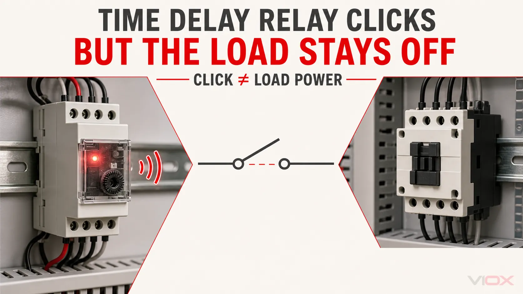
If a time delay relay completes its delay and clicks but the load does not operate, troubleshoot the output circuit in this order: verify the external source at COM, confirm the correct normally open or normally closed terminal, test whether the contact changes state, and trace the load and its return path. A click or output light does not prove that usable voltage reaches the load.
The most common cause is an unfed dry contact. Many time delay relays use potential-free output contacts: the timer opens and closes the contact, but it does not generate load voltage. Other common causes include incorrect COM/NO/NC wiring, an open fuse or conductor, a missing neutral or 0 V return, a damaged high-resistance contact, an unsuitable inductive load, or a failed load device.
This article begins after the timer has completed its expected timing sequence. If the relay does not power up, start timing, or reach its output state, use the broader time delay relay troubleshooting guide first.
Key Takeaways
- A click confirms internal movement, not successful power delivery to the load.
- An output light usually represents the timer’s commanded state; it may not verify the physical contact or downstream circuit.
- Many timer outputs are dry contacts and require an external source connected to COM.
- Identify COM, normally open (NO), and normally closed (NC) from the exact model diagram; terminal numbers vary.
- Test resistance or continuity only on an isolated, de-energized circuit.
- A contact can pass a low-current continuity test but fail when switching its real load.
- Check the complete load path, including source, fuse, interlocks, conductor, load, and neutral or 0 V return.
- Replace the timer only after verifying that the correct timing sequence occurred and the external circuit is healthy.
Safety: Isolate all relevant sources and verify absence of voltage before changing wiring or using resistance or continuity mode. Live voltage measurements should be performed only by qualified personnel using suitable instruments, personal protective equipment, and the required site procedure. Never assume the output circuit is de-energized because the timer’s own supply is off; dry contacts may switch a separate source.
Quick Symptom-to-Cause Table
| Observed condition | Most likely cause | What to verify | Corrective direction |
|---|---|---|---|
| Timer clicks, but COM has no voltage | Dry contact has not been supplied | External source at the COM terminal | Feed COM from the correct protected source according to the circuit design |
| COM is supplied, but the chosen output never becomes live | Wrong NO/NC terminal or contact did not transfer | Exact terminal diagram and isolated contact state | Correct the terminal selection or assess the timer output contact |
| Output light turns on, but COM–NO does not close | Output relay or mechanical contact failure | Isolated continuity before and after a controlled timing cycle | Replace the timer if the documented output state is not achieved |
| Contact passes continuity, but the load remains off | Open downstream circuit, failed load, or contact fails under load | Switched voltage, return path, interlocks, load condition | Repair the external circuit or replace the unsuitable or damaged component |
| Load input receives voltage, but the load does not operate | Missing return, load fault, protection or interlock open | Neutral or 0 V, overload, fuse, permissive contacts, load | Restore the return or repair the downstream device |
| Voltage collapses when the load should energize | Weak source, excessive voltage drop, loose connection, or unsuitable contact duty | Supply and contact voltage while the fault occurs | Correct the source or connection and use a properly rated switching device |
| Relay works without the load but fails with it connected | Inrush, inductive duty, or damaged high-resistance contact | Actual load type and model-specific contact rating | Use a suitable contactor or interposing relay and correct surge protection as required |
| Load remains energized when the output should release | Wrong NC path, parallel feed, or welded contact | Isolated contact state and unintended bypass circuits | Correct the wiring or replace a welded output contact |
First Separate Timer Logic from Load Power
A DIN-rail time delay relay normally contains two functional sections:
- The timing and control section receives the timer supply and, where applicable, a start, trigger, gate, or reset signal.
- The output section opens or closes a contact that switches an external circuit.
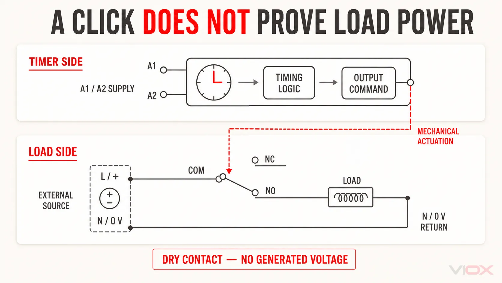
These sections may be electrically isolated. Therefore, voltage applied to A1 and A2 does not necessarily appear at the output terminals. The timer can be powered, complete its delay, illuminate its output indicator, and click while the load circuit remains unpowered.
This behavior is normal when the output is a dry contact. The contact acts like a switch: it can connect COM to NO or COM to NC, but it needs an external source to switch. Macromatic’s official time-delay-relay guidance describes the same principle: applying input voltage initiates the timer, but the voltage used by the load must be supplied through the output-contact circuit.
For a broader explanation of timer supply, trigger, and output terminal groups, see the time delay relay wiring diagram guide.
Use the Four-Point Output-Path Test
Treat the output circuit as one continuous path:
Source at COM → contact transfer → switched output conductor → load and return
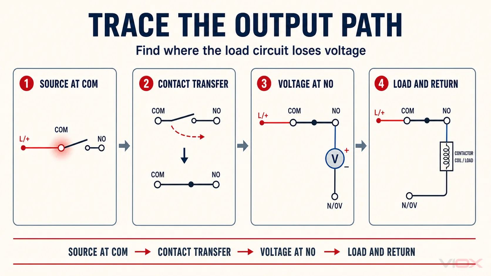
Testing in this order prevents a common mistake: replacing the timer before confirming that the contact received a source or that the load circuit had a complete return path.
1. Confirm the Timer Reached the Intended Output State
Before diagnosing the load circuit, confirm that the observed click occurs at the correct point in the timing sequence. Compare the power, trigger, output indication, and contact state with the timing chart for the exact model.
Do not use sound alone as the timing reference. A nearby contactor, interposing relay, valve, or other control device may be producing the click. Place the measurement at the timer output and verify the output state identified in its documentation.
If the timer has not completed its sequence, return to the general time delay relay not-working procedure linked in the introduction. Supply, trigger, reset, and function-selection faults are separate upstream problems.
2. Identify COM, NO, and NC from the Exact Diagram
Do not identify terminals by physical position alone. A common IEC-style convention for one changeover contact is 15 for COM, 16 for NC, and 18 for NO, but not every timer, socket, or output channel follows that arrangement. Plug-in timers and multi-output models can use different pin assignments.
Use the diagram printed on the relay, socket, or datasheet to identify:
- the timer supply terminals;
- any trigger or reset terminals;
- COM for the output contact;
- the contact closed in the normal state;
- the contact closed after the timed output operates;
- any second contact set.
Normally open and normally closed refer to the documented normal or reset state, not necessarily to whether the machine should be running.
3. Verify the External Source at COM
If the output is a dry contact, COM must receive the voltage that the circuit intends to send to the load. The source may be the same control supply that powers the timer, or it may be a separately protected source. The circuit design determines which is correct.
For a qualified person performing an approved live test, measure from COM to the correct reference conductor. Depending on the circuit, that reference may be neutral, 0 V, or the other side of the control supply. A reading across two unrelated circuits or incorrect reference points can be misleading.
If COM has no source, inspect upstream items such as:
- a control fuse or miniature circuit breaker;
- an emergency-stop or permissive contact;
- a loose terminal or broken conductor;
- an open overload contact;
- an incorrectly placed jumper;
- a controller output that was expected to supply COM but does not.
An unfed COM is an external wiring condition, not evidence of a failed timer.
4. Test Whether the Contact Actually Transfers
Isolate and de-energize the output circuit before using resistance or continuity mode. Disconnect enough of the external circuit to prevent a parallel path from creating a false result.
Check the contact in both documented states:
- before the timed output operates;
- after a controlled timing cycle completes.
For a typical changeover contact, COM–NC should be closed in one state while COM–NO is open; after transfer, those states reverse. Use the exact timing chart because interval, off-delay, and other functions may return the contact differently.
If the output indicator changes but neither contact follows the documented sequence, the output relay, mechanical linkage, socket connection, or terminal path may be defective. Omron’s relay troubleshooting guidance similarly separates failure of the relay drive system from failure of the contact that conducts the load.
5. Verify the Switched Voltage Under Operating Conditions
A continuity test uses very little current. It can confirm that a path exists, but it cannot prove that the contact will carry the actual control load reliably.
After the isolated test is complete and the circuit has been restored safely, a qualified person can verify:
- source voltage at COM;
- voltage at the selected NO or NC terminal in each output state;
- voltage at the load input;
- voltage across the closed contact while current is flowing;
- control-supply behavior when the load attempts to energize.
A healthy closed contact should introduce little voltage drop relative to the circuit. Do not apply a universal pass/fail voltage because acceptable values depend on the timer, contact material, load current, instrument, and manufacturer specification. A repeatable, significant drop across a supposedly closed contact—especially when the load is connected—indicates resistance at the contact, socket, or terminal that requires investigation.
6. Trace the Load and Its Return Path
If the correct switched voltage leaves the timer, the timer is no longer the primary suspect. Trace the circuit through every downstream element:
- switched conductor from the timer;
- fuse, interlock, overload, or permissive contact;
- contactor coil, solenoid, lamp, controller input, or other load;
- neutral, 0 V, or return conductor;
- terminal blocks, plugs, and field wiring.
The load may receive voltage on one side and still fail because the return is open. A contactor may also receive insufficient voltage to pick up even though a high-impedance meter displays a nominal-looking value with no load current. When diagnosing a contactor or relay coil, compare the measured voltage with the device’s documented operating requirements; the relay coil voltage guide explains rated, pick-up, drop-out, and holding voltage as separate quantities.
Why the Output Light Is Not Proof of Contact Conduction
On many electronic timers, the output indicator is controlled by the internal timing logic. It tells the technician that the timer has commanded an output state. Depending on the model, it may not independently monitor whether the mechanical contact completed its travel, whether COM is supplied, or whether current reaches the load.
Interpret the indicators in layers:
| Indicator or observation | What it can support | What it does not prove |
|---|---|---|
| Power light on | Timer supply is present internally at some level | Supply is correct under load or present at COM |
| Timing indication active | A timing cycle has started according to the timer logic | Trigger remains stable or the output will complete |
| Output light on | Internal logic commanded the output state | Contact continuity, load voltage, or load operation |
| Audible click | A mechanical device moved | Correct terminal selection or successful current flow |
| Load operates | The complete circuit conducted enough current | Contact rating is appropriate for long-term service |
Indicator meanings vary by model. Use the manufacturer legend rather than assuming that every green or red light has the same function.
Common Wiring Errors Behind This Symptom
COM Is Not Fed
The timer receives power at A1/A2, but the output contact has no external source. The timer operates normally and the load receives nothing.
The Load Is Connected Between NO and NC
NO and NC are alternative switched terminals referenced to COM. Connecting a load only between NO and NC does not create the intended source-to-load path.
The Wrong Contact State Is Used
The load is connected to NC when the design expects it to energize after the timed output transfers to NO, or vice versa. The result may look like no operation, reversed operation, or an output that turns off at the wrong time.
The Return Conductor Is Missing
The timer switches the line or positive conductor correctly, but the load has no neutral or 0 V return. Measuring only the switched side can conceal this open circuit.
A Parallel Feed Bypasses the Timer
Another contact or wiring path supplies the load independently. This can create unexpected voltage, keep the load energized, or produce false continuity readings while the timer is isolated.
Timer Power and Load Power Are Confused
The timer’s operating supply and the contact circuit are treated as if they were internally connected. Unless the exact diagram shows an internal connection, treat them as separate circuits.
When the Contact Works Without Load but Fails Under Load
This result points to load duty, contact condition, terminal resistance, or supply capacity rather than timing logic.
The Headline Ampere Rating May Not Match the Load
A timer may display a current rating based on a resistive load. A contactor coil, solenoid, valve, or other electromagnetic load is inductive and can impose inrush and switching stress that differs from steady-state current.
Check the model’s utilization category and load-specific contact rating rather than relying only on the largest printed ampere value. The VIOX guide to time relay contact failure on inductive loads explains why AC-1 and AC-15 ratings cannot be treated as interchangeable.
A Damaged Contact Can Pass a Meter Test
A pitted, contaminated, or high-resistance contact may conduct a meter’s test current but drop excessive voltage when the real load is connected. Intermittent socket pressure, a loose terminal, or heat-damaged conductor can create the same symptom.
Do not open or repair a sealed timer relay unless the manufacturer explicitly provides a service procedure. For a modular control component with a repeatable internal contact fault, replacement is normally the safer corrective path.
The Load May Need an Interposing Device
If the load duty exceeds the timer contact’s documented capability, use an appropriately rated interposing relay or contactor. The timer then switches the interposing device’s coil, and that device switches the final load.
Any surge-suppression method must match the coil type, voltage, release-time requirement, controller output, and manufacturer guidance. Do not add a diode, resistor-capacitor network, or varistor based only on a generic diagram.
Output-Side Measurement Checklist
| Check point | Expected condition | If the result is abnormal |
|---|---|---|
| Exact model and terminal diagram | Supply and output terminals positively identified | Stop and obtain the correct diagram |
| Timer output state | Delay completed and documented output state reached | Return to general timer troubleshooting |
| Source at COM | Correct protected source present | Repair upstream supply or wiring |
| COM–NO and COM–NC, isolated | Contact state follows the model timing chart | Inspect socket/terminal; replace timer if internal failure is confirmed |
| Selected output terminal, energized test | Switched voltage appears in the correct state | Investigate contact, socket, terminal, or reference conductor |
| Voltage across closed contact under load | Low relative to the circuit and stable | Investigate high resistance or damaged contact path |
| Load input and return | Complete circuit with adequate operating voltage | Repair downstream wiring, protection, interlock, or load |
| Actual load duty | Within model-specific contact capability | Use a correctly rated interposing device or replacement |
When to Replace the Time Delay Relay
Replace the timer when the external circuit has been verified and one of these conditions remains repeatable:
- the timer reaches its documented output state but the isolated contact does not transfer;
- the contact is intermittent while the socket and terminal connections are confirmed sound;
- the contact remains stuck or welded after the initiating condition is removed;
- a closed contact produces an abnormal, repeatable voltage drop under a valid load;
- visible cracking, discoloration, odor, or heat damage is present;
- the output works only without load even though the actual load is within the model-specific contact rating and the supply circuit is sound.
Replacing the timer without correcting the root cause can produce the same failure again. Before installation, confirm supply type, timing function, trigger method, terminal arrangement, contact configuration, utilization category, and the actual load duty. Use the timer relay selection guide when building the replacement specification.
For model evaluation after the circuit requirements are known, review the VIOX DIN-rail timer relay range.
Quick Diagnostic Sequence
- Confirm that the click came from the timer and occurred at the correct point in the timing sequence.
- Obtain the exact terminal diagram.
- Identify COM, NO, and NC.
- Verify that COM receives the intended external source.
- Isolate the circuit and test contact transfer safely.
- Restore the circuit under an approved procedure and verify the switched voltage.
- Trace the load, protection, interlocks, and return conductor.
- Check the actual load duty against the timer’s model-specific contact rating.
- Replace the timer only if the output contact fails after the external circuit is proven healthy.
Frequently Asked Questions
Why does my time delay relay click but have no output voltage?
The output is probably a dry contact, so the timer does not generate voltage at NO or NC. Connect the correct protected external source to COM according to the circuit design, then verify whether the intended contact transfers after the delay.
Does the output light prove that the timer contact is working?
Not necessarily. On many timers, the light represents the internal command to the output. It may not verify mechanical contact movement, voltage at COM, contact conduction, or the downstream load circuit. Confirm the exact indicator meaning in the model documentation.
Can a relay click even if its contacts are damaged?
Yes. The mechanism can move while the electrical contact remains open, intermittent, contaminated, pitted, welded, or too resistive for the connected load. Official relay troubleshooting guidance distinguishes drive-system movement from contact conduction failure.
Can a timer contact pass continuity but still fail to run the load?
Yes. A multimeter continuity test uses very little current. A damaged contact, loose socket, or poor terminal can pass that test but develop excessive voltage drop when the real load is connected. Verify the circuit under valid operating conditions using an approved test procedure.
Which terminals should supply the load?
The external source normally enters COM and leaves through NO or NC according to the required output state. Common timer-relay numbering includes 15/16/18, but pin assignments vary. Use the diagram for the exact relay and socket.
Can a time delay relay switch a motor directly?
Only if the exact timer contact is explicitly rated for that motor load and operating duty. Many timer contacts are intended for control circuits rather than direct motor switching. An appropriately rated contactor is normally used when the final load exceeds the timer contact’s documented capability.
Should I replace the timer or repair the wiring first?
Verify the output path first. If COM is supplied, the correct terminal is selected, the downstream circuit is complete, and the contact still fails to follow the documented timing sequence, replacement is justified. If the contact transfers correctly, repair the external source, wiring, interlock, return path, or load instead.
Conclusion
When a time delay relay clicks but the load does not operate, the fastest diagnosis is not to repeat the entire timing setup. Start at the output and follow the power path: source at COM, contact transfer, switched conductor, load, and return.
This method separates an unfed dry contact or wiring fault from a genuine timer output failure. It also prevents a low-current continuity result from being mistaken for proof that the contact can switch the real load. Replace the timer only after its output contact and the complete external circuit have been tested against the exact model documentation and the actual load duty.