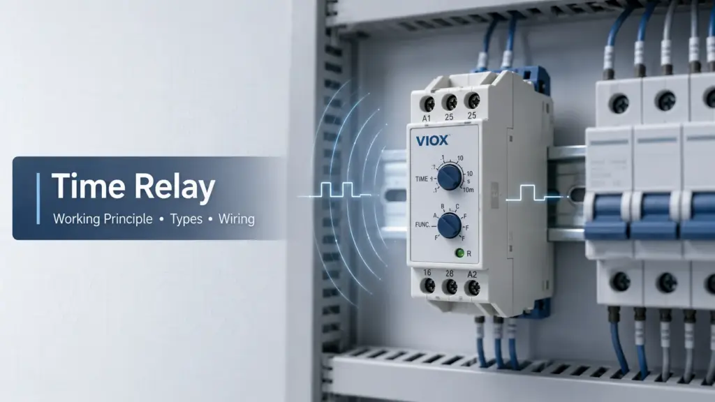
What Is a Time Relay?
A time relay, also called a timer relay or time delay relay, is an electrical control device that opens, closes, holds, or repeats an output contact action after a preset time condition. It is used when a circuit needs delayed starting, delayed stopping, interval timing, cyclic operation, star-delta transition, pump protection, HVAC sequencing, lighting control, or simple machine timing.
The difference from a standard relay is simple: a normal relay changes state as soon as its coil or input receives a signal. A time relay adds a timing circuit, so the output changes only after the selected timing logic has been satisfied.
For product specifications and model options, see the VIOX Timer Relay product page. This article focuses on the core device: what it does, how it works, how the terminals are usually read, and how to avoid common selection mistakes.
Quick Comparison: Relay vs Time Relay vs Timer Switch vs PLC Timer
| Device | Main function | Best used for | Typical limitation |
|---|---|---|---|
| Standard relay | Switches contacts immediately after a coil or input signal | Basic control, interlocking, signal isolation | No built-in timing function |
| Time relay | Switches contacts after a preset delay or timing sequence | Motor delay, pump delay, fan run-on, sequencing, alarms | Limited to defined timing functions |
| Timer switch | Switches by clock schedule or countdown time | Lighting schedules, street lights, daily or weekly switching | Usually not designed for industrial control logic |
| PLC timer | Software-based timing inside programmable logic | Complex automation, HMI-adjustable timing, diagnostics | Requires PLC hardware, programming, and maintenance access |
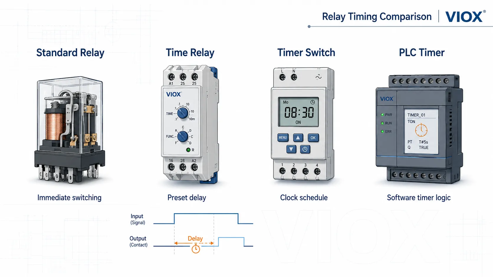
This distinction matters because people use "time relay" for several related needs. If the job is one fixed timing function inside a control panel, a time relay is often the cleanest solution. If the job is clock scheduling, use a timer switch. If the timing depends on many inputs, alarms, recipes, or HMI settings, PLC timing is usually better.
For a deeper comparison between standalone relay timing and software timing, see Timer Relay vs PLC Timer.
How Does a Time Relay Work?
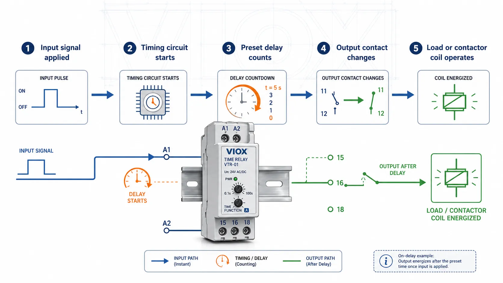
A time relay couples a timing element to an output switching element. When supply voltage or a control signal is applied, the timing circuit begins counting. When the preset time expires, the output contact changes state and controls another device, such as a contactor coil, solenoid valve, signal lamp, or PLC input.
The basic sequence is:
- Input signal or supply voltage is applied. The relay receives power through its supply terminals or receives a separate trigger signal.
- The timing circuit starts counting. The relay measures elapsed time using an electronic, digital, pneumatic, or motor-driven timing method.
- The preset time expires. The relay compares elapsed time with the selected dial, DIP switch, or digital setting.
- The output contact changes state. A normally open contact may close, or a normally closed contact may open, depending on the function.
- The relay resets, holds, or repeats. Reset behavior depends on the timing mode and wiring method.
This separation between the timing circuit and output contact is important. The time relay does not usually power the load directly through its timing electronics. Instead, the timer controls a relay contact, and that contact switches the external control circuit within its rated capability.
Timing Technologies Inside Time Relays
Modern DIN rail time relays are usually electronic or digital, but older or specialized designs may use pneumatic or motor-driven mechanisms. The timing technology affects accuracy, repeatability, vibration tolerance, service behavior, and application fit.
| Timing technology | How it works | Strengths | Watch points |
|---|---|---|---|
| Electronic timing | Uses RC circuits, integrated circuits, or microcontroller-based timing | Compact, common in modern DIN rail relays, easy to adjust | Check supply voltage range, electromagnetic interference environment, and datasheet accuracy |
| Digital timing | Uses a digital controller and display or programmed settings | Good readability, multi-range setting, often supports multifunction timing | More settings mean more documentation discipline |
| Pneumatic timing | Uses air restriction through a calibrated chamber or piston | Mechanically robust in some harsh environments | Timing can drift with aging, contamination, or environmental conditions |
| Motor-driven timing | Uses a small synchronous motor and cam mechanism | Useful in some older long-interval or line-frequency-linked applications | Larger, mechanical wear, less common in new compact panels |
Do not assume that one technology is always better. A simple analog time relay may be ideal for a fixed fan delay, while a digital multifunction timer may be better for OEM panels with multiple variants.
Main Parts of a Time Relay
| Part | What it does | What to check |
|---|---|---|
| Supply/input terminals | Power the timing circuit or receive the control signal | Rated supply voltage, AC/DC compatibility, trigger type |
| Timing circuit | Measures the delay interval | Timing range, repeat accuracy, reset behavior |
| Function selector | Selects on-delay, off-delay, interval, cyclic, or another mode | Function code must match the application |
| Time setting dial or display | Sets the delay value | Range scale, setting resolution, readability |
| Output contacts | Switch the controlled circuit | Contact rating, load type, NO/NC arrangement |
| Status indicator | Shows supply, timing, or output state | Useful for commissioning and troubleshooting |
| Mounting base or DIN rail clip | Holds the relay in the panel | DIN rail, socket, plug-in, or panel-mount format |
The most important practical point is that supply voltage and output contact rating are different specifications. A 24 VDC timer relay may switch an AC control circuit if the output contact is rated for that load. A contact rated for 250 VAC does not mean the relay supply terminals can accept 250 VAC unless the datasheet says so.
Main Types of Time Relays
Different timing functions are used for different control sequences. The function name matters more than the shape of the device.
| Time relay type | How it works | Typical applications |
|---|---|---|
| On-delay relay | Output changes state only after the input has been energized for the preset delay | Sequential start, motor delay, power-up stabilization |
| Off-delay relay | Output remains active for the preset time after the input signal is removed | Fan run-on, pump delay, ventilation purge |
| Interval relay | Output turns on immediately after trigger, stays on for a preset time, then turns off | Alarm pulse, valve actuation, timed output |
| One-shot or pulse relay | Produces one timed output pulse from a trigger | Signal shaping, short actuation, reset pulse |
| Repeat cycle relay | Alternates ON and OFF at set intervals while powered | Flashing lights, cyclic pumps, periodic lubrication |
| Star-delta timer | Controls the transition from star to delta in a motor starter | Reduced-voltage motor starting |
| Multifunction time relay | Provides several selectable timing functions in one unit | OEM panels, spare-parts reduction, flexible commissioning |
For a broader guide to timing functions, see Time Delay Relays: Complete Guide to Types, Functions, and Applications. If your decision is between fixed-function and multifunction models, see Multifunction Timer Relay vs Single-Function Timer Relay.
On-Delay Time Relay
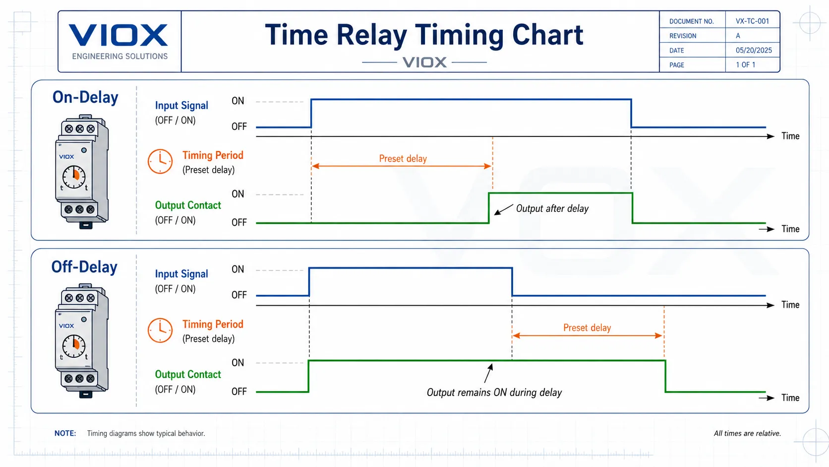
An on-delay time relay waits after the input is energized before changing its output contact state. If the input is removed before the delay expires, the relay usually resets and the output does not change.
Example: A conveyor motor should start five seconds after the main system starts, giving upstream equipment time to stabilize. An on-delay relay receives the start signal, counts the preset delay, then energizes the contactor coil.
Common uses include:
- Sequential motor starting
- Compressor restart delay
- Power-up stabilization
- Delayed alarm activation
- Machine startup sequencing
Off-Delay Time Relay
An off-delay time relay keeps the output active for a preset time after the input signal is removed. This is the opposite field behavior from on-delay timing.
Example: A ventilation fan should continue running after a heating process stops. When the control signal turns off, the off-delay relay keeps the fan contactor energized until the preset delay expires.
Common uses include:
- Fan run-on after shutdown
- Pump run-on or drain delay
- Ventilation purge
- Delayed lamp shutoff
- Controlled release of auxiliary circuits
A common mistake is treating an off-delay relay as a drop-in replacement for an on-delay relay. In many circuits, an off-delay relay must first be energized or "armed" before it can time after the signal is removed.
Also confirm which kind of off-delay behavior your circuit requires. A true off-delay timer can continue timing briefly after complete power loss, usually using internal stored energy such as a capacitor. A control-signal off-delay timer keeps continuous supply power on A1/A2 and starts timing only when a separate trigger or control input changes state. These two designs can look similar in a catalog but behave very differently in a panel.
Always check whether the relay uses two-wire supply timing, a separate control input, or stored-energy timing before replacing one function with another.
Time Relay Wiring Basics: A1/A2, 15/16/18, NO and NC Contacts
Time relay wiring varies by manufacturer and function, so the printed diagram on the relay body or datasheet is always the final authority. However, many industrial timer relays use common terminal conventions.
| Marking | Common meaning | Practical note |
|---|---|---|
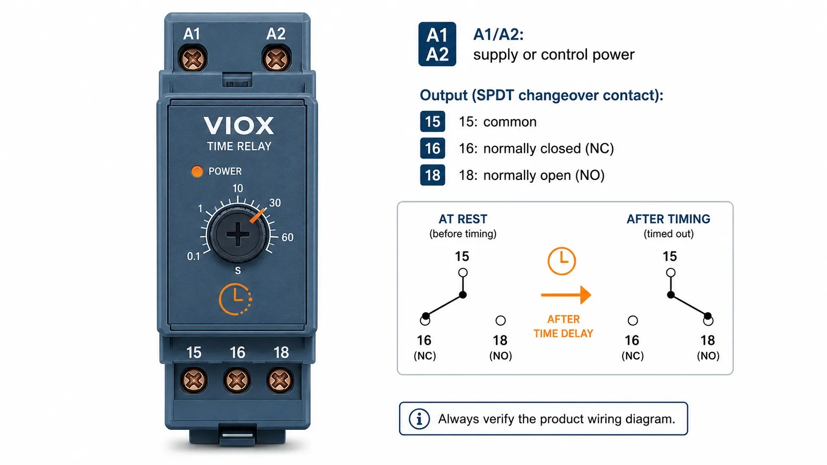
| A1 / A2 | Supply or control power terminals | Confirm AC/DC voltage and polarity requirements on the datasheet |
| 15 | Common terminal of changeover contact | Often the moving/common contact in an SPDT output |
| 16 | Normally closed contact | Connected to 15 when the relay is in the normal/rest state |
| 18 | Normally open contact | Connected to 15 after the relay output changes state |
| NO | Normally open | Open at rest, closes when output operates |
| NC | Normally closed | Closed at rest, opens when output operates |
A simple single-pole changeover timer relay may therefore use A1/A2 for supply and 15/16/18 for the output contact. In this arrangement, the timer relay does not usually power the load directly from A1/A2. Instead, the output contact switches a separate control circuit, such as a contactor coil, signal lamp, solenoid, or PLC input.
For detailed diagrams, see the Time Delay Relay Wiring Diagram Guide. For motor starter wiring specifically, see How to Wire a Time Relay for a Motor Starter.
Contact Rating: Why Load Type Matters
A time relay contact is still a relay contact. Its life depends heavily on what it switches.
Resistive loads are usually easier to switch than inductive loads. Contactor coils, solenoids, small motors, valves, and electromagnetic devices can create higher stress during switching because stored magnetic energy must be released. For this reason, datasheets may list different ratings for resistive loads and control-circuit loads, including utilization categories such as AC-15 and DC-13 where applicable.
For example, a relay contact that is listed around 10 A at 250 VAC for a resistive load may have a much lower rating when switching an inductive control load such as a contactor coil. In many datasheets, the AC-15 control-circuit rating can be only a fraction of the AC-1 resistive-load rating. A common real-world pattern is a contact that looks generous for resistive duty but is only suitable for a few amps in inductive duty. The exact number must come from the relay datasheet, but the engineering lesson is fixed: do not use the headline ampere rating without checking the load category.
In practice, do not select a time relay contact by ampere value alone. Check:
- contact voltage and current rating
- AC or DC switching duty
- resistive vs inductive load type
- inrush current or coil pickup current
- whether suppression is needed for coils or solenoids
- whether an interposing relay or contactor should switch the actual load
For this failure mode, see Why Time Relay Contacts Fail on Inductive Loads.
Where Are Time Relays Used?
Time relays are used wherever a control circuit needs predictable timing without full PLC logic. They are especially common in relay panels, motor starters, HVAC controls, pump systems, lighting circuits, and simple automation equipment.
Motor Control and Star-Delta Starting
In motor control panels, time relays are used to delay motor starting, sequence multiple loads, control auxiliary circuits, or manage star-delta transition timing. A star-delta timer changes the starter from star connection to delta connection after a preset acceleration period.
Pump and Compressor Protection
Pumps and compressors can be damaged by rapid cycling. A time relay can enforce a restart delay so the equipment does not start again immediately after stopping. This is common in HVAC compressor protection, water pump control, and pressure-based systems.
For dedicated application guides, see Prevent Pump Short Cycling with a Time Delay Relay and HVAC Time Delay Relay for Compressor Protection.
Fan Run-On and Ventilation
Off-delay relays are often used to keep fans running after the main equipment stops. This supports heat removal, purge cycles, odor extraction, or ventilation after occupancy.
Lighting and Signaling
Time relays can provide delayed lighting, flashing signals, timed alarms, staircase lighting, and warning lamps. For clock-based daily or weekly schedules, however, a timer switch may be more appropriate than an industrial time relay.
Process and Packaging Lines
In simple machines, a time relay can create a basic sequence without a programmable logic controller. Examples include delayed conveyor start, timed valve output, lubrication pulses, reject gate actuation, intermittent agitation, and alarm delay.
For complex sequencing with many inputs, interlocks, alarms, and HMI-adjustable timing, PLC logic is usually the better architecture.
How to Choose a Time Relay
The correct time relay is selected by function first, then by electrical and mechanical requirements.
| Selection factor | What to confirm | Why it matters |
|---|---|---|
| Timing function | On-delay, off-delay, interval, cyclic, star-delta, multifunction | The wrong function gives the wrong circuit behavior |
| Supply voltage | 12 VDC, 24 VDC, 110/120 VAC, 220/230 VAC, or universal range where offered | Incorrect voltage can prevent operation or damage the relay |
| Timing range | Seconds, minutes, hours, or multi-range | The setting must cover the actual delay with enough adjustment resolution |
| Output contact rating | Voltage, current, AC/DC rating, load type | Contact life depends strongly on the load being switched |
| Load type | Resistive, inductive, contactor coil, solenoid, lamp, motor auxiliary circuit | Inductive loads stress contacts more than resistive loads |
| Reset behavior | Power reset, trigger reset, manual reset, memory behavior | Affects restart after power loss or control interruption |
| Mounting format | DIN rail, plug-in socket, panel mount | Must match the control panel layout |
| Environment | Temperature, humidity, vibration, enclosure conditions | Affects reliability and timing stability |
| Documentation | Datasheet, wiring diagram, function code, applicable approvals | Needed for engineered panels and purchasing approval |
For a full selection workflow, use How to Choose the Right Timer Relay. If voltage is the main question, see the Timer Relay Voltage Selection Guide.
Standards and Compliance Notes
For engineered panels, do not select a time relay only by function name or front-panel marking. Confirm the actual datasheet, approval file, and market requirement for the specific model.
Standards and compliance references may include:
- IEC 61812 series for time relays used in industrial and residential applications
- IEC 60947-5-1 where the relay is evaluated as a low-voltage control circuit device
- IEC 61810 series for electromechanical elementary relays where relevant to relay construction
- UL 508 or UL 60947-5-1 for North American industrial control equipment contexts, depending on product scope and certification
- CE marking in Europe as a conformity marking, not as a standalone product standard
The safe rule is simple: verify standards and approvals by exact model number. A logo on a catalog page is not enough for a specification-grade project.
Common Time Relay Mistakes
1. Choosing by time range only
A relay with the right delay range can still be wrong if the function, voltage, contact rating, trigger type, or reset behavior does not match the circuit.
2. Confusing supply voltage with contact rating
A time relay may be powered by 24 VDC while its output contact switches an AC control circuit, or it may be powered by AC while switching a low-voltage signal. These are separate ratings and must be checked separately.
3. Replacing off-delay with on-delay without checking circuit logic
On-delay and off-delay timers respond to different parts of the input signal. Even if the timing range and contact rating look similar, the circuit behavior may be completely different.
4. Switching inductive loads without checking contact duty
Contactor coils, solenoids, small motors, and valves can generate contact stress that is not obvious from the ampere number alone. If the relay contact is switching an inductive load, confirm the applicable contact duty and manufacturer guidance.
5. Using an ordinary time relay for a safety function
A standard time relay is not automatically a safety timer. If timing is part of a safety-related control function, use devices and architecture designed and certified for that safety role.
6. Selecting a multifunction relay without documenting the setting
Multifunction relays are useful, but they introduce setup risk. Record the selected function, time range, and final setting on the panel drawing or inside the enclosure.
7. Ignoring the printed wiring diagram
Terminal markings can look similar across brands, but functions and trigger methods vary. Always check the relay’s own wiring diagram before energizing the circuit.
How to Tell if a Time Relay Is Failing
Time relay faults often look like wiring faults, contactor faults, or PLC logic faults. Before replacing the relay, check the input power, timing setting, trigger signal, and output contact behavior with the panel drawing in hand.
| Field symptom | Likely issue | What to check |
|---|---|---|
| Indicator shows output OFF, but the load keeps running | Output contact may be welded closed | Isolate power, test continuity across the output contacts, and check whether the relay has been switching an inductive load without suppression |
| Relay powers up, timing starts, but output never changes | Wrong function setting, failed output contact, or missing trigger condition | Verify function selector, timing range, trigger input, and contact continuity |
| Relay chatters or resets during timing | Unstable supply voltage or control signal | Measure supply at A1/A2 during operation and check for loose terminals or voltage dips |
| Relay is dead after replacement | Wrong supply voltage or polarity | Confirm the model voltage before energizing; do not connect a 24 VDC relay to a 230 VAC control circuit |
| Timing works on bench but fails in the panel | Load interference, incorrect reset logic, or wiring difference | Compare bench wiring with the real panel diagram and check whether inductive loads need surge suppression |
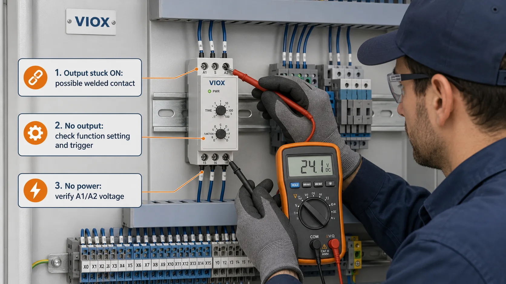
Two failure modes are especially common in maintenance work. Contact welding happens when the relay contact has been overstressed, often by inductive loads or inrush current. The relay may appear to turn off, but the load remains energized because the contact is physically stuck. Coil or electronics damage often follows wrong supply voltage, incorrect AC/DC selection, sustained over-voltage, or severe electrical noise in the control cabinet.
Time Relay FAQ
What is a time relay?
A time relay is a relay with a built-in timing function. It changes its output contact state after a preset delay or timing sequence instead of switching immediately when the input signal is applied.
Is a time relay the same as a timer relay?
In most industrial control contexts, yes. Time relay, timer relay, and time delay relay are commonly used to describe the same product category. Specific manufacturers may use different names for particular function families.
What is the difference between a time relay and a standard relay?
A standard relay changes contact state immediately when its coil or input is energized. A time relay adds a timing circuit, so the contact changes after a preset delay, pulse, interval, or repeat-cycle function.
What is the difference between a time relay and a timer switch?
A time relay is usually a control-panel component used for industrial timing functions such as on-delay, off-delay, interval, or motor sequencing. A timer switch usually operates by clock schedule, countdown, or daily/weekly switching for lighting and building loads.
What is an on-delay time relay?
An on-delay time relay waits after the input is energized before operating its output contact. It is commonly used for delayed motor start, sequential startup, power stabilization, and delayed alarm activation.
What is an off-delay time relay?
An off-delay time relay keeps its output active for a preset delay after the input signal is removed. It is commonly used for fan run-on, pump delay, ventilation purge, and delayed lamp shutoff.
What do A1 and A2 mean on a time relay?
A1 and A2 commonly identify the supply or control power terminals of a timer relay. The exact voltage, AC/DC compatibility, and polarity requirements must be checked on the product marking or datasheet.
What do 15, 16, and 18 mean on a time relay?
On many industrial relays, 15 is the common contact, 16 is normally closed, and 18 is normally open. This convention is common but not universal, so always confirm the printed diagram on the device.
Can a time relay control a motor directly?
Usually, a time relay should not switch a motor power circuit directly unless the contact rating explicitly supports that load. In most motor-control panels, the time relay switches a contactor coil or control circuit, and the contactor switches the motor power.
Can a time relay replace a PLC?
Only for simple, local timing tasks. A time relay is suitable for fixed delays such as fan run-on, motor auxiliary timing, pump delay, or interval output. A PLC is better when timing depends on multiple inputs, interlocks, diagnostics, recipes, communication, or HMI-adjustable values.
How do I choose the right time relay?
Start with the required function: on-delay, off-delay, interval, cyclic, star-delta, or multifunction. Then confirm supply voltage, timing range, contact rating, load type, mounting format, reset behavior, and applicable panel requirements.
Summary
A time relay is a compact way to add controlled timing to an electrical circuit without full PLC logic. It can delay starting, delay stopping, create timed pulses, repeat on/off cycles, or coordinate simple machine sequences.
For ranking and selection, the key is not just knowing that the device "delays a relay." The real engineering decision is matching the timing function, supply voltage, output contact duty, wiring method, reset behavior, and documentation to the actual circuit.
VIOX supplies timer relay products for panel builders, OEM equipment, motor auxiliary circuits, pump control, lighting, ventilation, HVAC, and general automation timing. Review the Timer Relay product page for model options, or visit Timer Relay Manufacturer for supplier and OEM support.
