

On this page
Introduction
When selecting a miniature circuit breaker (MCB) for an electrical installation, most engineers focus on the rated current, but ambient temperature also affects performance. The IEC 60898-1 reference temperature is 30°C. Temperature correction values must come from the specific MCB manufacturer’s datasheet; there is no universal derating table for every model.
Understanding MCB ambient temperature ratings and derating factors is essential for electrical professionals who need to ensure reliable protection in diverse operating conditions. Whether you’re designing a control panel for a desert climate, specifying breakers for an enclosed machinery cabinet, or troubleshooting nuisance tripping issues, temperature considerations play a defining role.
This comprehensive guide examines how ambient temperature affects MCB performance, explains the derating calculation methodology, and provides practical guidance for real-world installations. By the end, you’ll understand how to properly select and apply MCBs across varying thermal environments, ensuring both safety and operational reliability.
Understanding MCB Temperature Ratings
The Standard Reference Temperature
Every MCB is calibrated and tested at a specific reference ambient temperature, which serves as the baseline for its nominal current rating. For IEC 60898-1 household and similar circuit breakers, that reference is 30°C (86°F). The rating applies under the specified reference and installation conditions; it is not an exact instantaneous tripping threshold.
Under IEC 60947-2, check the manufacturer’s declared reference temperature for the particular device. 40°C (104°F) is a common reference for relevant industrial products, but it is not a universal calibration temperature for every IEC 60947-2 breaker. The standard designation alone does not supply the temperature correction factor.
How MCBs Are Rated
The rated current (In) marked on an MCB identifies its current rating under the manufacturer’s specified reference and installation conditions. Overload operation follows a time-current characteristic rather than an exact trip at In. This rating is determined through testing where the MCB’s thermal trip element, typically a bimetallic strip, is calibrated to activate the trip mechanism under specified overcurrent conditions.
The bimetallic strip is the heart of an MCB’s overload protection. It consists of two different metals bonded together, each with a different coefficient of thermal expansion. When current flows through the strip, it generates heat. As temperature rises, the metals expand at different rates, causing the strip to bend. Once it bends sufficiently, it triggers the trip mechanism, disconnecting the circuit.
This elegant thermal-mechanical system works precisely at the calibrated reference temperature. However, it’s also inherently sensitive to the ambient temperature surrounding the MCB, which is where derating becomes critical.
The Temperature Range Limitation
The permitted operating range and the current correction table are separate manufacturer specifications. Do not assume that every MCB can operate at 70°C simply because another series has a table extending to that temperature. For example, the public VIOX VOE3-63 catalogue states an ambient operating range of -5°C to +40°C. A different manufacturer’s high-temperature correction table does not extend that range.
Conversely, in colder environments below the reference temperature, an MCB may allow higher current before thermal tripping. This does not authorize exceeding the device’s declared rating or the limitations of the connected cables and equipment.
How Ambient Temperature Affects MCB Performance
The Physics of Thermal Tripping
The relationship between ambient temperature and MCB performance is rooted in basic thermal physics. The bimetallic strip inside an MCB must reach a specific temperature to trip. This temperature is achieved through two heat sources: the heat generated by the current flowing through the strip (I²R heating) and the heat from the surrounding environment (ambient temperature).
When ambient temperature increases, the bimetallic strip starts from a higher baseline temperature. It therefore requires less additional heating from current flow to reach its trip point. Its thermal time-current response shifts; the manufacturer’s correction data describes the resulting application limit. This is not a change to the marked current rating or a prediction of an exact trip current.
Current Capacity Reduction
The amount of reduction depends on the series, current rating, tripping characteristic and specified installation conditions. Do not apply a fixed percentage reduction per temperature increment. Read the corresponding row in the manufacturer’s table, including its reference temperature and permitted operating range.
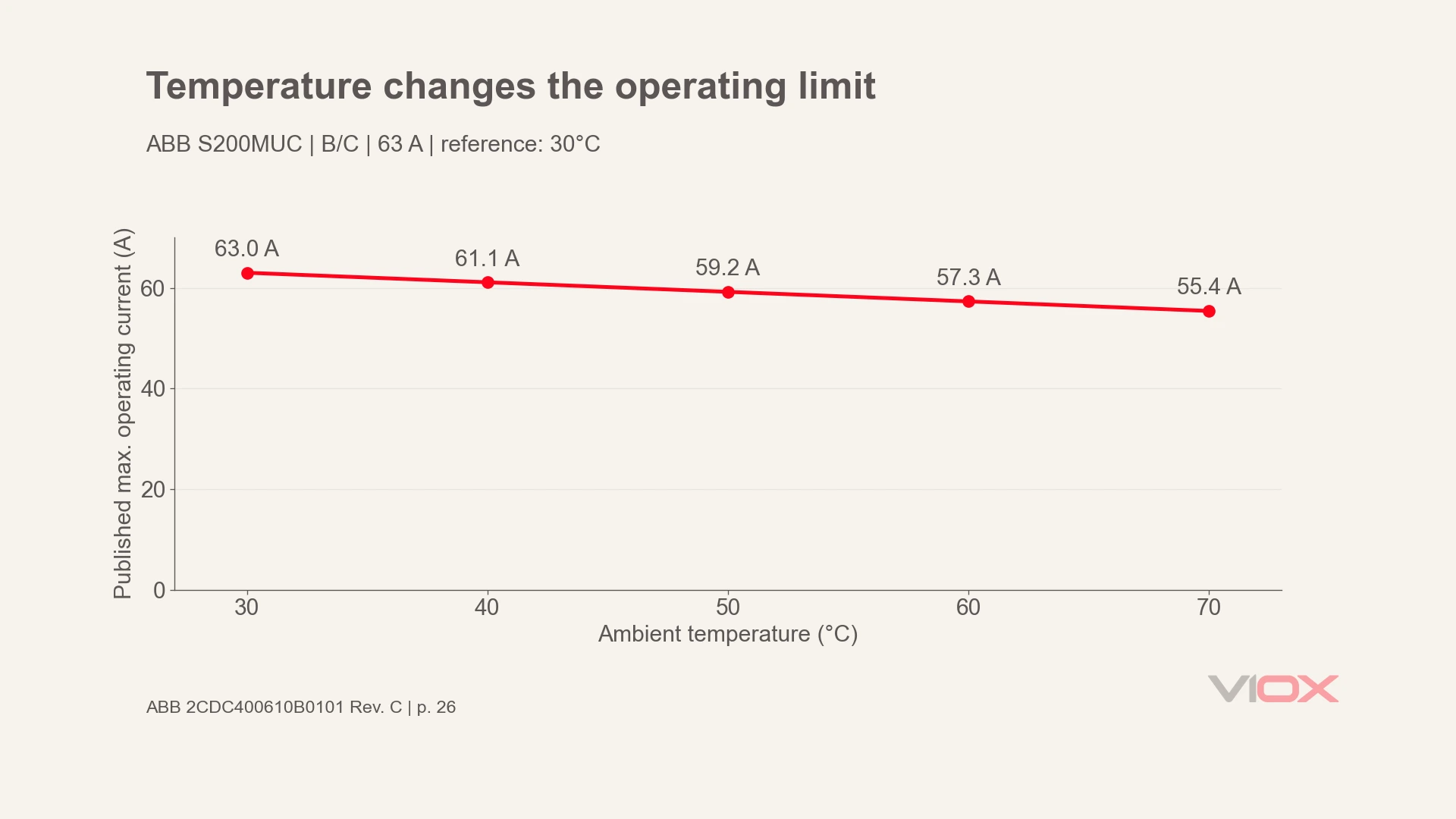
The verified S200MUC example below illustrates this method for one series only. Its values cannot be transferred to VIOX or other MCBs.
Failure Modes from Inadequate Derating
When MCBs operate in higher ambient temperatures without proper derating consideration, two primary failure modes emerge:
Nuisance Tripping: The MCB may trip during normal operation when the load exceeds the manufacturer’s temperature-adjusted application limit, even though it is below the marked current rating. This leads to unexpected downtime, productivity losses, and frustration for operators who see no apparent overload.
Premature Aging: Excessive temperature can accelerate deterioration of insulation and other internal components. A correction factor is not permission to operate outside the declared temperature range or ignore signs of damage.
Both scenarios undermine the fundamental purpose of the MCB: reliable, predictable circuit protection.
Derating Factors Explained
What Is a Derating Factor?
A derating factor (also called a temperature correction factor or ambient temperature correction factor) is a multiplier applied to an MCB’s nominal rating to determine its temperature-adjusted current limit under the manufacturer’s stated conditions.
The mathematical relationship is straightforward:
Effective Current Capacity = Rated Current × Derating Factor
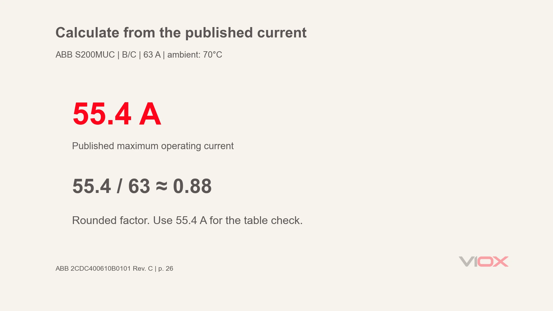
Where the manufacturer publishes a maximum operating current directly, use that value. A factor can be calculated by dividing the published current by In. Keep sufficient precision: multiplying by a rounded factor may not reproduce the table exactly. The result is an application limit, not a guaranteed tripping threshold.
How Derating Factors Are Determined
Derating factors are not theoretical calculations; they’re empirically derived through testing by manufacturers. The resulting tables or curves are specific to a product line and its stated conditions.
This is why it’s critical to consult the manufacturer’s technical documentation rather than relying solely on generic industry rules of thumb. Different MCB designs, internal component layouts, and thermal management features can result in varying derating characteristics even for breakers with the same nominal rating.
The Derating Curve
Manufacturers typically present derating information in two formats: tabular data and graphical curves. A derating curve plots ambient temperature on the X-axis against either the derating factor or the effective current capacity on the Y-axis.
The shape and available temperature points depend on the product. Do not assume a progressively steeper curve, a high-temperature plateau, or permission to interpolate beyond the manufacturer’s instructions. A graph ending at a temperature does not itself establish an operating-temperature approval for another model.
Practical Calculation Examples
The following examples all use ABB S200MUC, B/C characteristic, In = 63 A, reference temperature 30°C. Source: ABB application handbook 2CDC400610B0101 Rev. C, June 2021, page 26, table “Baureihe S200MUC”. They demonstrate reading and calculation, not VIOX performance.
Example 1: Basic Derating at 50°C
The manufacturer lists 59.2 A maximum operating current. The calculated factor is 59.2 / 63 = approximately 0.94. Use the published 59.2 A value for the thermal capacity check; do not substitute an assumed generic factor.
Example 2: Verification at 60°C
The same table lists 57.3 A. Compare the actual design load with that value, then check the manufacturer’s other installation conditions. If the load exceeds it, review the thermal design, load or device specification. Do not simply fit a higher-current breaker: the conductors, equipment and protective coordination must remain suitable. See the separate circuit breaker sizing and load calculation guide for the wider selection task.
Example 3: Reverse Calculation at 70°C
The table lists 55.4 A. Dividing 55.4 by 63 gives approximately 0.88. The rounded factor is convenient for explanation, while 55.4 A remains the published current value. This example does not establish suitability at 70°C for a different series.
These examples demonstrate why temperature derating must be an integral part of MCB selection, not an afterthought.
Standard Derating Tables & Guidelines
Typical Derating Values
There is no verified universal table to apply here. Use a model-specific table instead. The following table applies only to ABB S200MUC, B/C characteristic, 63 A, with a 30°C reference. It is not a general MCB table and must not be used as VIOX correction data.
| Ambient temperature | Published maximum operating current | Calculated factor, current / 63 A |
|---|---|---|
| 30°C, reference | 63.0 A | 1.00 |
| 40°C | 61.1 A | 0.97 |
| 50°C | 59.2 A | 0.94 |
| 60°C | 57.3 A | 0.91 |
| 70°C | 55.4 A | 0.88 |
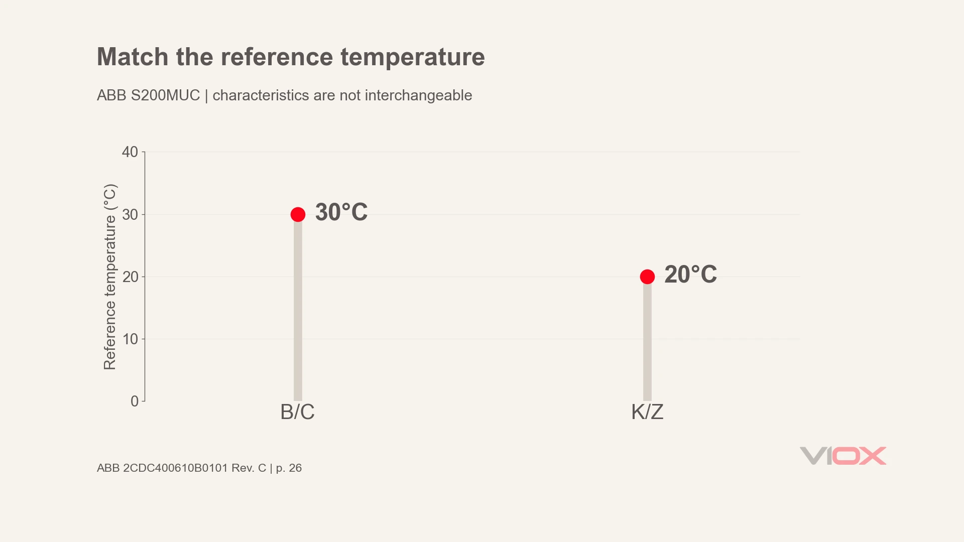
Source: ABB application handbook 2CDC400610B0101 Rev. C, page 26. Current values are transcribed from the B/C, 63 A row; factors are calculated and rounded. The K/Z portion uses a 20°C reference, so it must not be mixed with the B/C portion.
MCCBs require their own model-specific correction data. Many industrial products use a 40°C reference, but verify the declared calibration temperature and trip-unit type. MCCB values cannot be substituted for MCB values.
Manufacturer-Specific Data
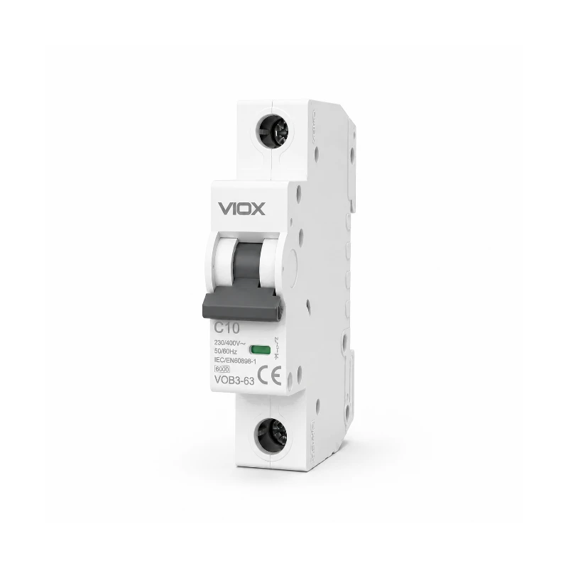
The public VIOX VOB3-63 and VOB3-63H catalogues state a 30°C reference temperature. The VOE3-63 catalogue states 30 ± 2°C for its listed tripping tests and an operating ambient range of -5°C to +40°C.
The linked public catalogues reviewed for these three series do not contain temperature-current correction tables. Request the exact-model table and its installation conditions before specifying a temperature-adjusted current. A time-current tripping curve is not an ambient-temperature correction table.
The ABB table above provides one traceable manufacturer example. Other brands and series need their own matching documentation; an unspecified product family or current rating is insufficient evidence for a numerical example.
IEC Standards Guidance
IEC 60898-1 and IEC 60947-2 establish applicable product and test requirements. They do not supply one universal table of temperature correction factors. IEC 60898-1 uses the 30°C reference; for IEC 60947-2, establish the manufacturer’s declared reference for the model. Obtain correction values from its datasheet or application instructions.
When to Apply More Conservative Factors
In certain scenarios, allowing more thermal margin is prudent:
- Mission-critical applications where any nuisance trip has severe consequences
- Installations with poor temperature monitoring where actual ambient may exceed design assumptions
- Aging installations where condition or calibration needs assessment
- Environments with wide temperature fluctuations that stress components through repeated thermal cycling
Use documented limits and engineering assessment to provide that margin. Do not invent a correction factor or use extra derating as a substitute for replacing a damaged device.
Practical Application & Installation Considerations
Defining Ambient Temperature in Real Installations
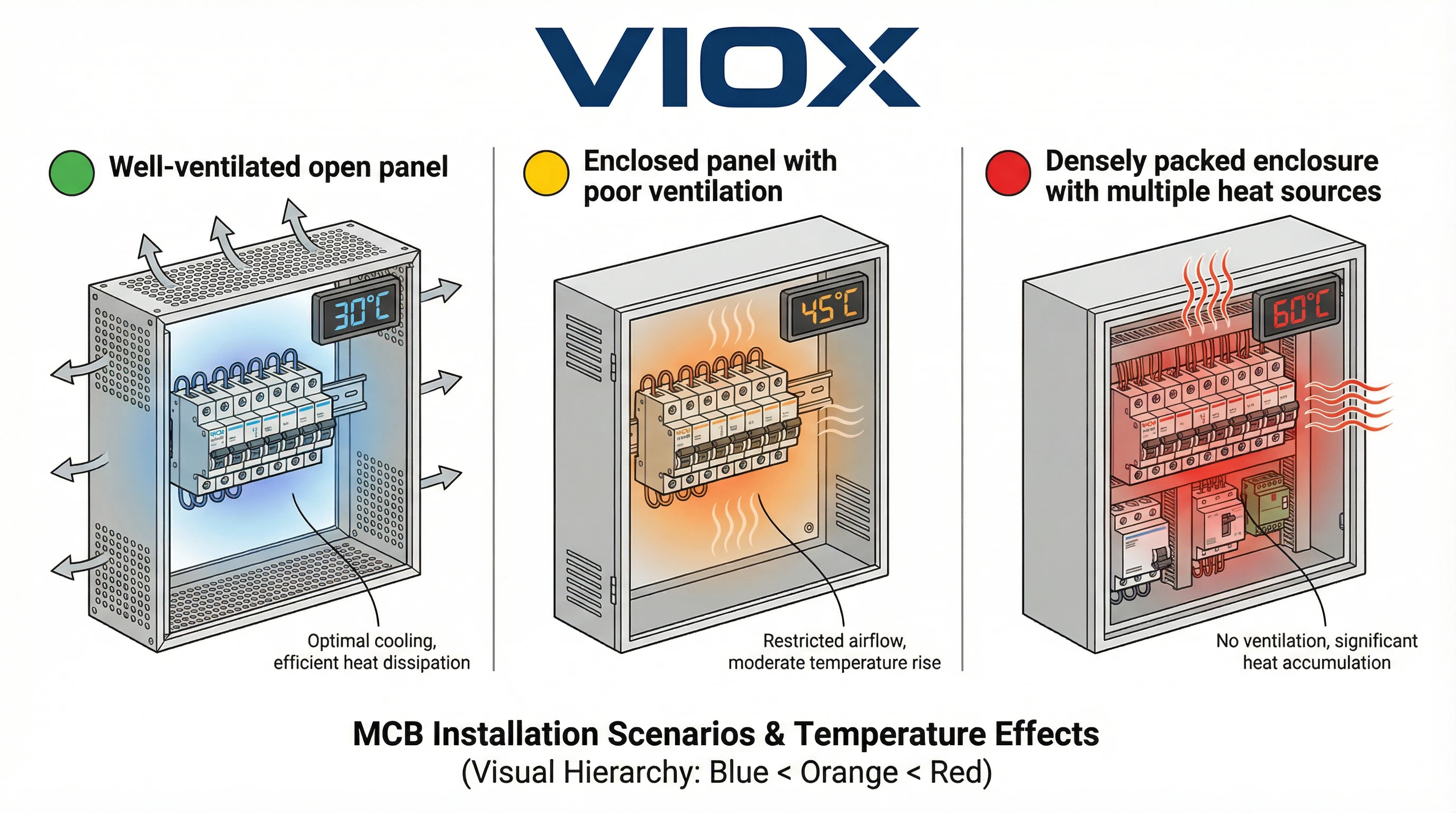
A critical point often misunderstood: ambient temperature for MCB derating purposes is not room temperature. It’s the temperature of the air immediately surrounding the MCB itself. In enclosed installations, this can be significantly higher than the general environment.
A panel’s internal temperature may rise above room temperature because of equipment losses, solar loading on the enclosure, or inadequate ventilation. Always measure or calculate the actual temperature inside the enclosure where the MCBs are mounted.
Enclosure Effects and Heat Accumulation
Electrical enclosures create localized hot zones. Heat sources include:
- Power supplies and transformers generating continuous heat
- VFDs (Variable Frequency Drives) with switching losses
- Contactors and relays with energized coils
- The MCBs themselves contributing I²R losses
In a densely packed panel without adequate ventilation, internal temperature can exceed external ambient. Determine the actual rise from the assembly’s heat balance or measurements. Ventilation, suitable spacing and thermal separation are possible mitigation measures. Contactor temperature limits require their own product assessment; MCB correction values do not apply to them.
Grouping Factors and Multiple MCBs
When multiple MCBs are mounted side-by-side in close proximity, their combined thermal output creates mutual heating effects. Check whether the manufacturer specifies a grouping factor or arrangement factor in addition to its ambient-temperature correction.
Use the instructions for the exact device arrangement, number of loaded poles and assembly conditions. Multiply separate temperature and grouping factors only when the manufacturer defines them for combined use. Do not apply an extra factor if the published rating already accounts for that installation. There is no universal reduction for a particular number of adjacent MCBs.
Ventilation and Thermal Management
Proper enclosure design significantly impacts MCB thermal performance:
- Natural convection: Ensure adequate clearance above and below MCB rows. Hot air must escape from top vents while cooler air enters from below.
- Forced ventilation: In high-density installations or hot environments, specify ventilation or cooling to maintain the components’ documented operating conditions. Verify the internal temperature rather than targeting an arbitrary rise above outdoor or room ambient.
- Thermal barriers: Isolate high-heat components (VFDs, power supplies) from MCB sections using baffles or separate compartments.
Cable Derating Coordination
A crucial but often overlooked point: cables connected to MCBs also require temperature derating. The overall circuit protection scheme is only as reliable as its weakest element.
Check the cable’s corrected current-carrying capacity independently using its applicable installation rules, insulation and terminal limitations. The MCB’s thermal capacity calculation alone does not establish cable protection. Do not increase the breaker rating to avoid nuisance tripping without checking the complete protective coordination. For the separate conductor-sizing task, see the wire gauge and circuit breaker sizing chart.
Altitude Considerations
Reduced air density at altitude can reduce cooling and affect insulation performance. Use the manufacturer’s stated altitude limit and correction instructions; a temperature table alone does not establish suitability at a different altitude.
Conclusion
Ambient temperature is a critical yet frequently underestimated factor in MCB selection and application. While an MCB’s nameplate rating provides essential information, its thermal application depends on the stated reference and installation conditions. Use 30°C for the IEC 60898-1 reference and verify the declared reference for an IEC 60947-2 device.
In real-world installations, especially within electrical enclosures or challenging thermal environments, the effective current-carrying capacity of an MCB can be significantly reduced. Ignoring temperature derating can lead to nuisance tripping and unreliable operation.
The key takeaways for electrical professionals:
- Always determine the actual ambient temperature at the MCB location, not just room temperature
- Consult manufacturer-specific derating tables rather than relying solely on generic guidelines
- Apply temperature and grouping corrections according to the manufacturer’s combined-use instructions
- Coordinate MCB derating with cable current-carrying capacity reductions
- Design enclosures with adequate ventilation to manage heat accumulation
For VIOX applications, consult the exact product catalogue and request any additional temperature correction data needed for the installation. The public catalogues reviewed here do not establish a VIOX high-temperature derating table. Proper MCB selection accounting for ambient temperature helps keep the protection system within its documented application conditions.
FAQ
What is the reference temperature for an MCB rating?
IEC 60898-1 uses a 30°C reference temperature for household and similar MCBs. For an IEC 60947-2 device, verify the manufacturer’s declared reference temperature for the exact model rather than assuming every device uses 40°C. The ABB S200MUC table discussed here uses 30°C for B/C and 20°C for K/Z characteristics.
Do I need to derate an MCB in a hot enclosure?
Check the air temperature immediately around the MCB against its declared conditions. If the manufacturer requires a temperature correction, apply its model-specific data and any documented grouping instructions. Stay within the permitted operating range; another series’ table cannot authorize operation outside it.
How do I calculate the effective current of an MCB at 50°C or 70°C?
Use the manufacturer’s published maximum operating current directly, or multiply the rating by its specified correction factor. For ABB S200MUC B/C 63 A only, the cited table lists 59.2 A at 50°C and 55.4 A at 70°C. Dividing by 63 gives approximately 0.94 and 0.88. These values are not VIOX or universal MCB factors.
Does derating apply the same way to MCCBs?
The need to account for temperature also applies to MCCBs, but their reference temperatures, trip-unit designs and correction data can differ. Check the exact MCCB’s declared conditions and manufacturer table. Do not transfer an MCB table to an MCCB or assume all IEC 60947-2 products use the same reference.
Where do I find the derating table for my MCB model?
Look in the exact series’ manufacturer datasheet, technical catalogue or application handbook under ambient-temperature correction or maximum operating current. Match the current rating, characteristic and installation conditions. If no table is published, request it from the manufacturer. The reviewed VOB3-63, VOE3-63 and VOB3-63H public catalogues do not contain temperature-current correction tables.