Direkte Antwort: Was ist eine Auslösekennlinie bei einem Leitungsschutzschalter?
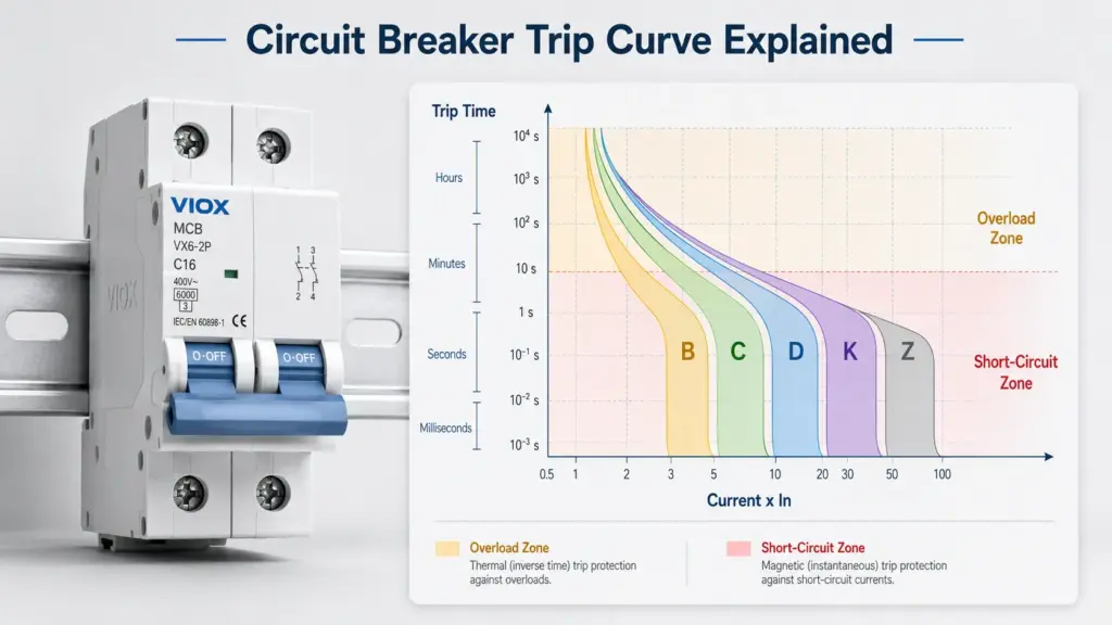
Eine Auslösekennlinie, auch Zeit-Strom-Kennlinie oder TCC genannt, zeigt, wie lange ein Schutzschalter bei verschiedenen Überstrompegeln benötigt, um auszulösen. Die horizontale Achse stellt üblicherweise den Strom als Vielfaches des Nennstroms des Schutzschalters dar, während die vertikale Achse die Auslösezeit angibt. Die Kennlinie hilft Ingenieuren bei der Auswahl eines Schutzschalters, der normale Einschaltströme toleriert, aber Überlastungen und Kurzschlüsse dennoch sicher abschaltet.
Einfach ausgedrückt beantwortet eine Auslösekennlinie diese Frage:
Wenn der Strom über den Normalwert steigt, wie schnell öffnet dieser Schutzschalter den Stromkreis?
Diese Antwort ist wichtig für Leitungsschutzschalter (MCBs), Kompaktleistungsschalter (MCCBs), RCBOs, Motorstromkreise, Transformatoren, LED-Beleuchtungsgruppen, Schaltschränke und industrielle Verteilungssysteme. Ein Schutzschalter, der zu früh auslöst, verursacht Fehlauslösungen. Ein Schutzschalter, der zu spät auslöst, schützt Kabel, Anlagen oder Personen möglicherweise nicht ausreichend vor Fehlerenergie.
Wichtigste Erkenntnisse
- Eine Auslösekennlinie ist ein Diagramm von Strom im Verhältnis zur Auslösezeit.
- Die horizontale Achse zeigt üblicherweise den Strom als Vielfaches des Nennstroms, wie zum Beispiel
1 x In,5 x In, oder10 x In. - Die vertikale Achse zeigt die erwartete Auslösezeit, oft auf einer logarithmischen Skala.
- Der untere linke Bereich stellt das Überlastverhalten dar; der Bereich hoher Ströme steht für die magnetische oder unverzögerte Auslösung.
- Die Kennlinien B, C, D, K und Z beschreiben unterschiedliche unverzögerte Auslösebereiche, hauptsächlich für Leitungsschutzschalter und ähnliche Geräte.
- Der Kennbuchstabe ändert nicht den Bemessungsstrom. Ein B16, C16 und D16 sind allesamt 16A-Geräte; ihr Auslöseverhalten bei Kurzzeitüberlast unterscheidet sich.
- Überprüfen Sie vor der endgültigen Auswahl immer die tatsächliche Zeit-Strom-Kennlinie des Herstellers, die Produktnorm, das Ausschaltvermögen und den verfügbaren Fehlerstrom.
Übersicht der Auslösekennlinien von Leitungsschutzschaltern
| Kurve Typ | Typischer magnetischer Auslösebereich | Einschaltstromtoleranz | Common Application | Hauptrisiko bei Fehlverwendung |
|---|---|---|---|---|
| Z-Charakteristik | Etwa 2-3 x In, abhängig vom Hersteller | Sehr niedrig | Empfindliche Elektronik, Halbleiterschaltungen, Steuerungsanlagen | Fehlauslösungen bei Lasten mit hohem Anlaufstrom |
| B-Kurve | Etwa 3-5 x In | Niedrig | Wohnraumbeleuchtung, ohmsche Lasten mit geringem Einschaltstrom, Endstromkreise | Kann bei Einschaltströmen von Motoren, Transformatoren oder LED-Treibern auslösen |
| C-Kurve | Etwa 5-10 x In | Medium | Gewerbliche Stromkreise, kleine Motoren, HLK-Anlagen, LED-Beleuchtungsgruppen, gemischte Lasten | Kann bei geringem verfügbarem Fehlerstrom zu langsam auslösen |
| K-Charakteristik | Oft etwa 8-12 x In, abhängig vom Hersteller | Mittel bis hoch | Motors, inductive loads, control circuits | Less universal; exact behavior must be checked by datasheet |
| D-Kurve | About 10-20 x In | Hoch | Transformers, welders, large motors, high-inrush industrial loads | Can fail fast disconnection if fault current is not high enough |
These ranges are practical reference values used in many IEC-style discussions. They are not a substitute for the manufacturer’s published curve, installation rules, or project specification. Type K and Type Z especially vary by product family.
For a broader MCB classification guide, see Types of MCB: B, C, D, K, Z Curves, Ratings, Poles, and Applications.
Auslösekennlinie vs. Zeit-Strom-Kennlinie vs. TCC
Im Bereich des Leitungsschutzes sind diese Begriffe eng miteinander verbunden:
| Begriff | Bedeutung | Typische Verwendung |
|---|---|---|
| Auslösecharakteristik | Allgemeiner Begriff dafür, wie schnell ein Schutzschalter bei verschiedenen Stromstärken auslöst | Gebräuchlich bei der Auswahl von Leitungsschutzschaltern (MCB) und Leistungsschaltern |
| Zeit-Strom-Kennlinie | Fachsprachliche Bezeichnung für die Strom-Zeit-Charakteristik | Technik, Datenblätter, Selektivitätsstudien |
| TCC | Abkürzung für Zeit-Strom-Kennlinie | Schutzkoordination und Selektivitätsstudien |
| Zeit-Strom-Kennlinie | In technischen Dokumenten häufig verwendete formelle Ausdrucksweise | Normen, Herstellerdokumentation |
Für die meisten praktischen Auslegungen von Schutzschaltern, Auslösekurve, Zeit-Strom-Kennlinieund TCC beziehen sich auf dasselbe Konzept: eine grafische Darstellung des Zusammenhangs zwischen Stromstärke und Auslösezeit.
Wie man eine Zeit-Strom-Kennlinie liest
Eine Zeit-Strom-Kennlinie wird üblicherweise mit logarithmischen Achsen gezeichnet. Dies kann zunächst verwirrend wirken, aber die Ablesemethode ist einfach.
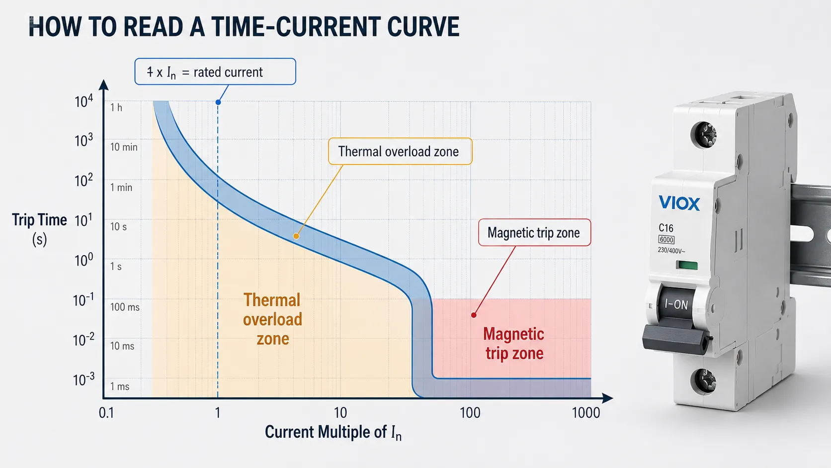
Schritt 1: Bestimmen Sie den Strom auf der horizontalen Achse
Die horizontale Achse stellt den Strom dar. In vielen Auslösekennlinien von Leistungsschaltern wird der Strom als Vielfaches des Nennstroms angegeben:
1 x Inbedeutet Nennstrom2 x Inbedeutet das Zweifache des Nennstroms5 x Inbedeutet das Fünffache des Nennstroms10 x Inbedeutet das Zehnfache des Nennstroms
Zum Beispiel: Wenn ein Leitungsschutzschalter für 20 A ausgelegt ist, dann:
| Vielfaches von In | Strom für einen 20-A-Leitungsschutzschalter |
|---|---|
| 1 x In | 20A |
| 2 x In | 40A |
| 5 x In | 100A |
| 10 x In | 200A |
Dies ist der Grund, warum zwei Leitungsschutzschalter mit derselben Amperezahl bei Anlauf- oder Fehlerbedingungen unterschiedlich reagieren können. Ihre Kennlinienverläufe können unterschiedlich sein.
Schritt 2: Bestimmen Sie die Auslösezeit auf der vertikalen Achse
Die vertikale Achse stellt die Zeit dar. Sie kann Sekunden, Millisekunden, Minuten oder eine logarithmische Zeitskala anzeigen. Bei geringer Überlast kann die Auslösung des Schutzschalters länger dauern. Bei hohem Fehlerstrom kann der Schutzschalter wesentlich schneller auslösen.
Dies ist beabsichtigt. Ein Schutzschalter sollte nicht jedes Mal sofort auslösen, wenn ein Motor anläuft oder ein Kondensator geladen wird. Er muss jedoch schnell genug auslösen, wenn der Strom auf einen tatsächlichen Fehler hindeutet.
Schritt 3: Lesen Sie das Kennlinienband ab, nicht eine einzelne dünne Linie
Viele Auslösekennlinien erscheinen eher als Band denn als exakte Linie. Dieses Band repräsentiert Fertigungstoleranzen, Temperatureinflüsse und den zulässigen Betriebsbereich des Geräts.
Gehen Sie nicht davon aus, dass der Schutzschalter immer bei einer exakten Sekunde oder einem exakten Strom auslöst. Verwenden Sie für die endgültige Auslegung die vom Hersteller veröffentlichte Kennlinie und die geltende Norm.
Schritt 4: Trennung der thermischen und magnetischen Zonen
Die meisten thermisch-magnetischen Niederspannungsschutzschalter weisen zwei Hauptauslöseverhalten auf:
| Kennlinienbereich | Was es bedeutet | Typische Fehlerart |
|---|---|---|
| Thermischer Überlastbereich | Verzögerte Auslösung durch anhaltenden Überstrom, der das Bimetallelement erwärmt | Überlastung |
| Magnetischer oder unverzögerter Bereich | Schnellauslösung durch hohen Strom, der einen elektromagnetischen Mechanismus betätigt | Kurzschluss oder sehr hoher Einschaltstrom |
Die genaue Kurvenform hängt vom Leistungsschaltertyp, der Baugröße, der Auslöseeinheit, der Norm und der Konstruktion des Herstellers ab.
Thermischer Auslösebereich: Überlastschutz
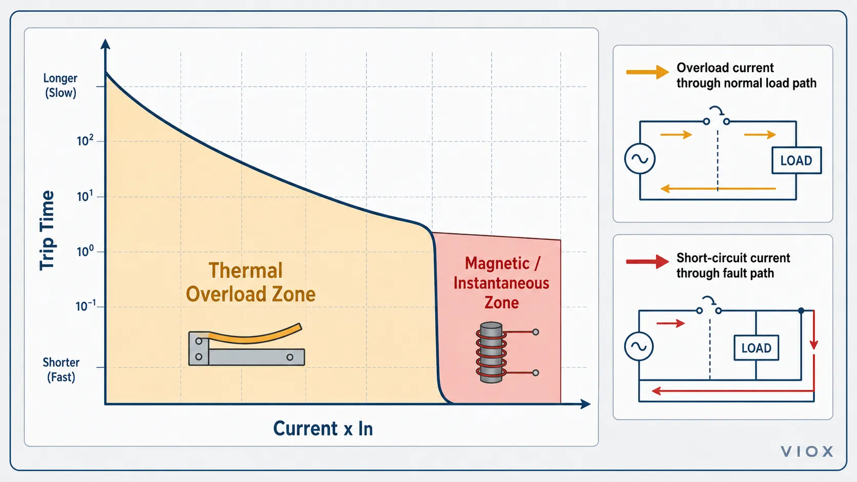
Der thermische Teil der Kennlinie schützt vor Überlastungen. Eine Überlastung ist ein Strom oberhalb des zulässigen Wertes, der normalerweise im normalen Leiterpfad verbleibt.
Beispiele hierfür sind:
- Zu viele Verbraucher an einem Stromkreis
- Motor läuft unter übermäßiger mechanischer Last
- Kabel führt mehr Strom als zulässig
- Heizung oder Gerät nimmt mehr Strom auf als erwartet
- Mangelhafte Belüftung führt zu Wärmestau im Schaltschrank
Die thermische Auslösung ist absichtlich verzögert. Wenn eine Last den Nennstrom kurzzeitig überschreitet, löst der Schutzschalter möglicherweise nicht sofort aus. Hält die Überlast jedoch lange genug an, um eine gefährliche Erwärmung zu verursachen, sollte der Schutzschalter auslösen.
Für eine detailliertere Erläuterung der Überlast als Fehlerzustand siehe Was ist eine Stromkreisüberlastung?.
Magnetischer Auslösebereich: Kurzschluss und hoher Einschaltstrom
Der magnetische oder unverzögerte Bereich reagiert auf hohe Ströme. Dies ist der Teil der Kennlinie, der am engsten mit den Auslösecharakteristiken B, C, D, K und Z verbunden ist.
Hohe Stromstärken können aus zwei sehr unterschiedlichen Situationen resultieren:
- einem gefährlichen Kurzschluss
- einem normalen, aber kurzzeitigen Einschaltstrom
Der Leitungsschutzschalter kann nicht “wissen”, ob der hohe Strom durch das Einschalten eines einwandfreien Transformators oder durch einen echten Kurzschluss verursacht wird. Er erfasst lediglich Stromstärke und Zeit. Die Kennlinie muss daher so gewählt werden, dass normale Einschaltströme nicht zu Fehlauslösungen führen, während ein tatsächlicher Fehlerstrom dennoch eine schnelle Abschaltung bewirkt.
Dies ist der zentrale Kompromiss bei der Auswahl der Auslösecharakteristik von Leitungsschutzschaltern.
Erläuterung der Auslösecharakteristiken B, C, D, K und Z
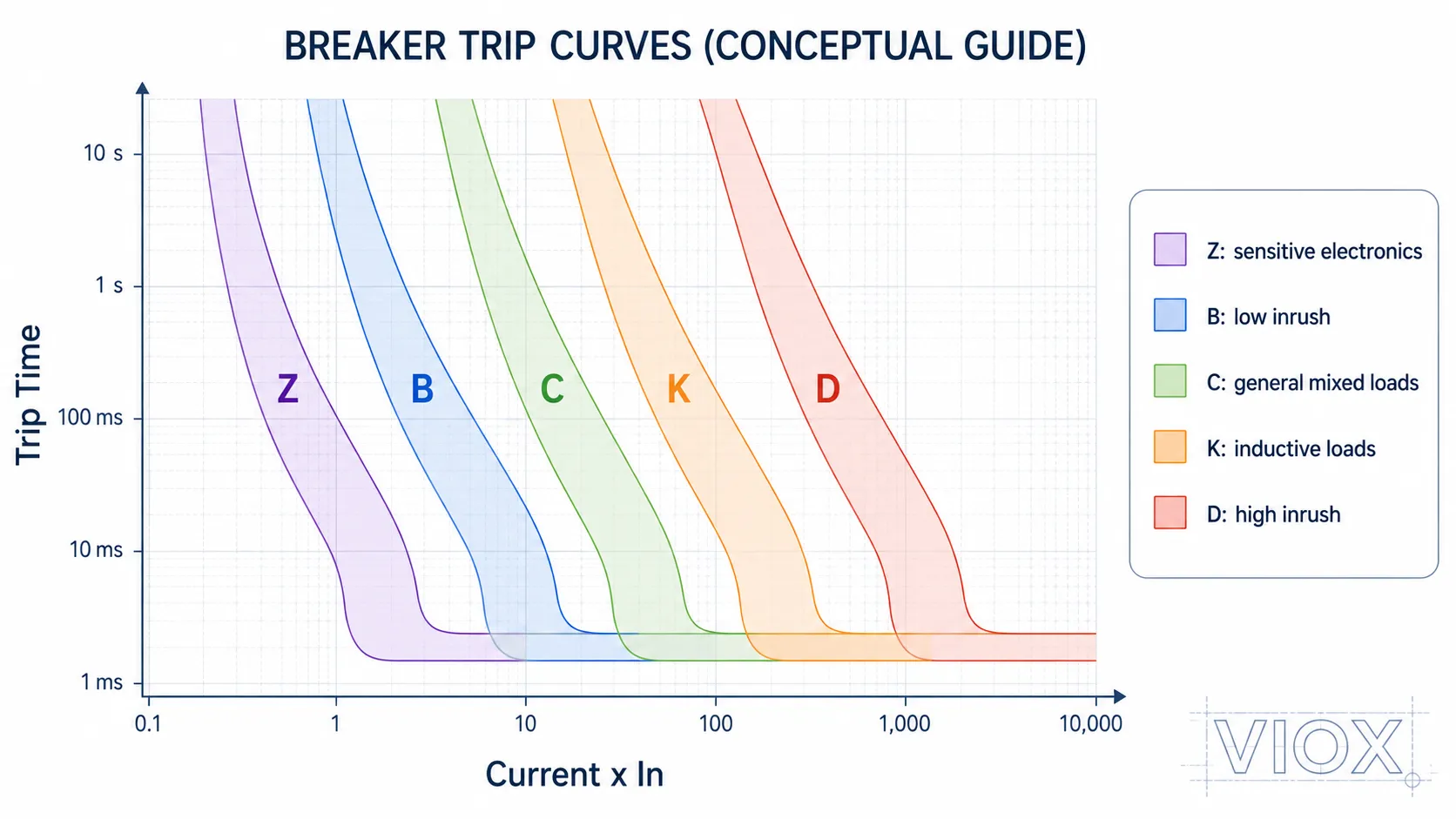
Leitungsschutzschalter mit B-Charakteristik
Ein Leitungsschutzschalter mit B-Charakteristik löst magnetisch typischerweise bei etwa dem 3- bis 5-fachen des Nennstroms aus.
Er wird üblicherweise in Betracht gezogen für:
- Endstromkreise mit geringem Einschaltstrom
- Wohnraumbeleuchtung
- ohmsche Lasten
- allgemeine Steckdosen- oder Abzweigstromkreise, sofern die örtlichen Vorschriften dies zulassen
- Stromkreise, bei denen der verfügbare Fehlerstrom begrenzt sein kann
Das Risiko besteht in Fehlauslösungen bei Motoren, Transformatoren, großen LED-Treibergruppen und Netzteilen mit hohen Einschaltströmen.
Leitungsschutzschalter mit C-Charakteristik
Ein Leitungsschutzschalter mit C-Charakteristik löst magnetisch typischerweise bei etwa dem 5- bis 10-fachen des Nennstroms aus.
Er wird üblicherweise verwendet für:
- gewerbliche Stromkreise
- gemischte Lasten
- kleine Motoren
- HVAC-Ausrüstung
- LED-Beleuchtungsgruppen mit moderaten Einschaltströmen
- allgemeine Schaltschränke
Die C-Charakteristik ist oft der praktische Mittelweg, erfordert jedoch dennoch einen ausreichend verfügbaren Fehlerstrom für eine zuverlässige Auslösung bei Kurzschlussbedingungen.
Leitungsschutzschalter mit D-Charakteristik
Ein Leitungsschutzschalter mit D-Charakteristik löst magnetisch typischerweise bei etwa dem 10- bis 20-fachen des Nennstroms aus.
Er wird für Lasten mit höheren Einschaltströmen verwendet, wie zum Beispiel:
- Transformatoren
- größere Motoren
- Schweißgeräte
- einige Industriemaschinen
- Lasten mit hohen magnetisierenden oder kapazitiven Einschaltströmen
Wählen Sie die D-Charakteristik nicht nur, um Fehlauslösungen zu vermeiden. Bei langen Leitungswegen oder hoher Fehlerschleifenimpedanz reicht der verfügbare Fehlerstrom möglicherweise nicht für eine schnelle magnetische Auslösung aus.
K-Charakteristik-Leitungsschutzschalter
K-Charakteristik-Leitungsschutzschalter werden häufig mit induktiven Lasten und Motorstromkreisen in Verbindung gebracht, das genaue Verhalten hängt jedoch stark vom Hersteller und der Produktreihe ab. Prüfen Sie das Datenblatt, bevor Sie die K-Charakteristik als direkten Ersatz für die C- oder D-Charakteristik verwenden.
Z-Charakteristik-Leitungsschutzschalter
Leitungsschutzschalter mit Z-Charakteristik sind empfindlicher und werden für Elektronik, Messstromkreise, halbleiterbezogene Schutzmaßnahmen und Anwendungen mit geringen Einschaltströmen eingesetzt. Bei Lasten mit hohem Anlaufstrom können sie zu schnell auslösen.
Beispiel: B16 vs. C16 vs. D16
Ein häufiger Irrtum ist die Annahme, ein C16-Schalter sei “stärker” als ein B16-Schalter. Das ist keine korrekte Betrachtungsweise.
Ein B16-, C16- und D16-Schalter haben alle denselben Bemessungsstrom: 16A. Der Unterschied liegt in ihrer magnetischen Schnellauslöseschwelle.
| Schutzschalter | Nennstrom | Typischer magnetischer Auslösebereich | Was es bedeutet |
|---|---|---|---|
| B16 | 16A | Etwa 48-80 A | Empfindlich gegenüber hohen Anlaufströmen |
| C16 | 16A | Etwa 80-160 A | Toleriert moderate Einschaltströme |
| D16 | 16A | Etwa 160-320 A | Toleriert hohe Einschaltströme, benötigt jedoch einen hohen Fehlerstrom für eine schnelle Auslösung |
Wenn ein B16-Leitungsschutzschalter beim Motorstart auslöst, kann der Austausch durch einen C16 Fehl-Auslösungen reduzieren. Bevor jedoch auf einen D16 gewechselt wird, müssen der verfügbare Fehlerstrom, die Leitungslänge, die Schleifenimpedanz, das Ausschaltvermögen und die örtlichen Vorschriften geprüft werden.
Für einen Leitfaden mit Fokus auf Einschaltströme siehe Erläuterung der LS-Schalter-Kennlinien B, C und D.
Vergleichstabelle: Kennlinien von Leitungsschutzschaltern vs. Zeit-Strom-Kennlinien von Schmelzsicherungen
Schmelzleiter-Zeit-Strom-Kennlinien und Leistungsschalter-Auslösekennlinien weisen nicht immer den gleichen Verlauf auf.
| Vergleichspunkt | Schmelzleiter-Zeit-Strom-Kennlinie | Leistungsschalter-Auslösekennlinie |
|---|---|---|
| Funktionsprinzip | Schmelzelement | Thermisch-magnetischer oder elektronischer Auslösemechanismus |
| Rückstellung nach Auslösung | Normalerweise nein | Normalerweise ja, nach Fehlerbehebung |
| Strombegrenzung | Kann bei strombegrenzenden Sicherungstypen stark ausgeprägt sein | Abhängig von der Konstruktion des Schutzschalters |
| Kennlinienform | Abhängig von der Sicherungsklasse und dem Elementdesign | Abhängig von der Auslöseeinheit und dem Mechanismus des Schutzschalters |
| Auswahlschwerpunkt | Sicherungsklasse, Spannung, Strom, I²t, Ausschaltvermögen | Kennlinientyp, Bemessungsstrom, Ausschaltvermögen, Selektivität |
Weitere Einzelheiten zur Abschaltzeit von Sicherungen und zur Ansprechzeit von Schutzschaltern finden Sie unter Ansprechzeit von Sicherung vs. Leitungsschutzschalter (MCB).
Auslösekennlinie und Ausschaltvermögen sind nicht dasselbe
Auslösekennlinie und Ausschaltvermögen beziehen sich zwar auf den Schutz, sind aber keine identischen Bemessungswerte.
| Begriff | Was sie beantwortet |
|---|---|
| Auslösecharakteristik | Wie schnell löst der Schutzschalter bei einem gegebenen Überstrom aus? |
| Nennstrom | Wie viel Strom kann das Gerät unter festgelegten Bedingungen führen? |
| Schaltleistung | Welchen maximalen Kurzschlussstrom kann das Gerät sicher unterbrechen? |
| Nennspannung | Bei welcher Systemspannung kann das Gerät sicher unterbrechen? |
Ein Leitungsschutzschalter kann die richtige Auslösecharakteristik, aber ein falsches Ausschaltvermögen aufweisen. Dies ist unsicher. Wenn der prospektive Kurzschlussstrom am Installationsort das Ausschaltvermögen des Schutzschalters übersteigt, kann dieser bei einem schweren Fehler versagen.
Für Anwendungen mit Leitungsschutzschaltern (MCB), siehe 6kA vs. 10kA LS-Schalter Ausschaltvermögen. Für Begriffe zur Bemessung von Leistungsschaltern im Industriebereich, siehe Icu vs. Ics vs. Icw vs. Icm Leistungsschalter-Bemessungswerte.
IEC 60898-1 vs. IEC 60947-2: Warum die Norm wichtig ist
Der gleiche Kennbuchstabe sagt nicht immer alles aus. Die Produktnorm und die Gerätefamilie sind entscheidend.
| Normkontext | Typischer Geräteumfang | Relevanz der Auslösekennlinie |
|---|---|---|
| IEC 60898 - 1 | Leitungsschutzschalter für den Hausgebrauch und ähnliche Zwecke zum Überstromschutz | Allgemeiner Kontext für Diskussionen zu MCBs mit B-, C- und D-Charakteristik |
| IEC 60947-2 | Industrielle Niederspannungs-Leistungsschalter | Industrielle Leistungsschalter können herstellerspezifische Zeit-Strom-Kennlinien und Einstellungen der Auslöseeinheit verwenden |
| UL 489 | Kompaktleistungsschalter und ähnliche Schutzschalter für nordamerikanische Anwendungen | Die Auswahl nordamerikanischer Schutzschalter folgt möglicherweise nicht derselben B/C/D-Kennzeichnungskonvention |
Gehen Sie nicht davon aus, dass jedes Diagramm der Auslösekennlinien direkt über verschiedene Normen, Marken oder Produktfamilien hinweg verglichen werden kann. Die endgültige Referenz sollte immer das Datenblatt des Herstellers und die geltende Projektnorm sein.
Für einen tiefergehenden Normenvergleich siehe IEC 60898-1 vs. IEC 60947-2.
Wie sich die Umgebungstemperatur auf die Auslösekennlinien auswirkt
Die Umgebungstemperatur beeinflusst hauptsächlich den thermischen Überlastbereich einer thermomagnetischen Auslösekennlinie. Das thermische Auslöseelement verwendet einen Bimetallmechanismus, sodass die Wärme innerhalb des Verteilers beeinflussen kann, wann der Schutzschalter bei anhaltender Überlast auslöst.
In der praktischen Schaltschrankmontage wird bei Fehlauslösungen manchmal fälschlicherweise die falsche Auslösecharakteristik verantwortlich gemacht, obwohl das eigentliche Problem die Wärmeentwicklung ist:
- Leitungsschutzschalter, die in eng beieinander liegenden DIN-Schienen-Reihen installiert sind
- hohe Umgebungstemperaturen innerhalb eines Außengehäuses
- mangelhafte Belüftung in einem Schaltschrank
- mehrere belastete Stromkreise, die gebündelt verlegt sind
- in der Nähe befindliche wärmeerzeugende Komponenten wie Schütze, Netzteile, Frequenzumrichter oder Transformatoren
Eine höhere Umgebungstemperatur kann dazu führen, dass der thermische Auslöser des Schutzschalters früher als erwartet anspricht. Eine niedrigere Umgebungstemperatur kann die thermische Reaktion verzögern. Dies ändert in der Regel nicht die magnetische Schnellauslöseschwelle, kann jedoch das Verhalten des Schutzschalters im Überlastbereich der Kennlinie beeinflussen.
Die richtige Reaktion besteht nicht automatisch darin, von der B-Charakteristik auf die C-Charakteristik oder von der C- auf die D-Charakteristik zu wechseln. Überprüfen Sie zuerst die Gehäusetemperatur, die Bündelung, den Laststrom, den Kabelquerschnitt und die Derating-Daten des Herstellers.
Wie man die richtige Auslösecharakteristik wählt
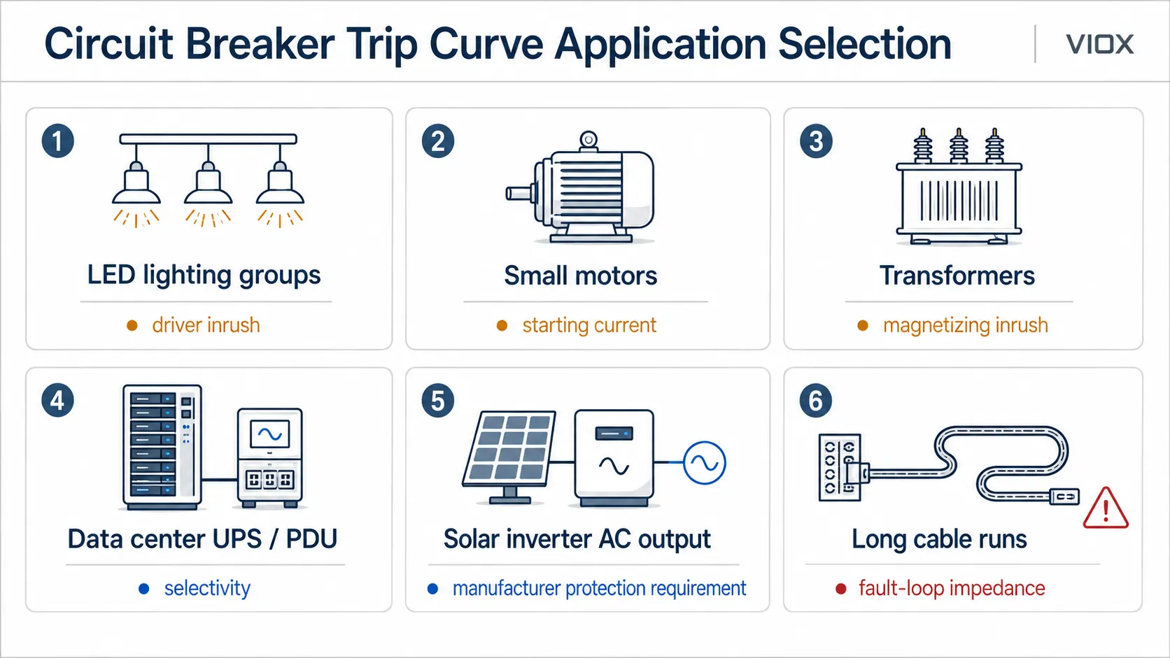
Gehen Sie von der Last und den Fehlerbedingungen aus, nicht nur vom Kennbuchstaben.
| Anwendung | Gemeinsamer Ausgangspunkt | Was zu überprüfen ist |
|---|---|---|
| Beleuchtung mit geringem Einschaltstrom oder ohmsche Lasten | B-Kurve | Lokale Installationsvorschriften, Leitungsschutz, verfügbarer Fehlerstrom |
| Gemischte gewerbliche Lasten | C-Kurve | Einschaltstrom von LED-Treibern, Steckdosenlasten, Fehlerschleifenimpedanz |
| LED-Beleuchtungsgruppen | Die C-Charakteristik wird häufig bei signifikanten Einschaltströmen in Betracht gezogen | Einschaltstrom des Treibers, Gruppierung, Schaltmethode, Historie von Fehlauslösungen |
| Kleine Motoren und Pumpen | C-Charakteristik oder motorspezifischer Schutz | Anlaufstrom, Überlastschutz, Kurzschlussschutz |
| Transformatoren | D-Charakteristik oder dedizierter Transformatorschutz | Magnetisierungsstrom, verfügbarer Fehlerstrom, vorgelagerte Selektivität |
| USV- oder PDU-Stromkreise in Rechenzentren | Herstellerspezifische Auswahl von Schutzschaltern | USV-Eingangs-/Ausgangsverhalten, Selektivität, verfügbarer Kurzschlussstrom, Koordination |
| AC-Ausgang des Solarwechselrichters | Anforderungen des Wechselrichters und des lokalen netzseitigen Schutzes beachten | Anlaufverhalten des Wechselrichters, AC-Ausgangsstrom, Fehlerbeitrag, Inselnetzschutz/Schutzkonzept |
| Empfindliche Elektronik | Z-Charakteristik, sofern verfügbar | Einschaltstrom, Fehlauslösungen, Herstellerhinweise |
| Motor- und induktive Lasten | C, D oder K, je nach System | Motoranlaufstrom, Koordination, Datenblattkennlinie |
| Lange Leitungslängen | Erfordert oft eine sorgfältigere Überprüfung der Kennlinie | Fehlerschleifenimpedanz, Spannungsfall, Abschaltzeit, thermische Belastbarkeit des Kabels |
| RCBO-Stromkreise | B-, C- oder D-Charakteristik plus Fehlerstrom-Typ | Verwechseln Sie nicht die Auslösekennlinie mit dem RCD-Typ AC/A/F/B |
Denken Sie bei der Auswahl von RCBOs daran, dass B/C/D eine Überstromauslösekennlinie, während Typ AC/A/F/B eine Klassifizierung der Fehlerstromwellenform ist. Siehe RCBO Typ AC vs. Typ A vs. Typ F vs. Typ B für die Fehlerstromseite.
Häufige Fehler beim Lesen von Auslösekennlinien
Fehler 1: Die Kennlinie als exakte Auslösezeit interpretieren
Eine Auslösekennlinie eines Schutzschalters ist in der Regel ein Band oder ein Toleranzbereich, kein einzelner exakter Auslösepunkt. Umgebungstemperatur, Produkttoleranzen, Installationsbedingungen und das Gerätedesign können den Betrieb beeinflussen.
Fehler 2: Wahl der D-Charakteristik zur Vermeidung jeder Fehlauslösung
Die D-Charakteristik kann zwar Fehlauslösungen reduzieren, erfordert jedoch auch einen höheren Fehlerstrom für die schnelle magnetische Auslösung. Ist der verfügbare Fehlerstrom zu niedrig, löst der Leitungsschutzschalter bei Fehlern möglicherweise nicht wie erwartet aus.
Fehler 3: Verwechslung von Bemessungsstrom und Auslösecharakteristik
Ein C20-Leitungsschutzschalter ist nicht einfach “größer” als ein B20-Schalter. Beide sind 20A-Geräte. Die Charakteristik bestimmt lediglich, wie der Schalter auf kurzzeitige hohe Ströme reagiert.
Fehler 4: Vernachlässigung des Leitungsschutzes
Der Leitungsschutzschalter schützt sowohl die Leitung als auch den Verbraucher. Eine Änderung der Charakteristik oder des Bemessungsstroms ohne Überprüfung des Leitungsquerschnitts und der Verlegeart kann ein Brandrisiko darstellen.
Fehler 5: Vergleich von Charakteristiken verschiedener Hersteller ohne Datenblätter
Zwei Leitungsschutzschalter mit identischer Kennbuchstaben-Bezeichnung weisen nicht zwingend das gleiche Zeit-Strom-Verhalten auf. Die Herstellerkennlinien sind maßgeblich, insbesondere für Selektivitätsbetrachtungen.
Fehler 6: Verwechslung von LS-Schalter-Charakteristiken und RCD-Typen
Ein LS-Schalter vom Typ B und ein RCD/RCBO vom Typ B bedeuten nicht dasselbe. Das eine bezieht sich auf das Auslöseverhalten bei Überstrom. Das andere bezieht sich auf die Erkennung von Fehlerstrom-Wellenformen.
Checkliste für das schnelle Lesen
Bevor Sie ein Auslösekennliniendiagramm für einen Leitungsschutzschalter verwenden, prüfen Sie:
- Bemessungsstrom des Schutzschalters
Unter - Charakteristik oder Einstellung der Auslöseeinheit
- thermischen Überlastbereich
- Bereich der magnetischen oder unverzögerten Auslösung
- Stromvielfaches auf der horizontalen Achse
- Auslösezeit auf der vertikalen Achse
- Toleranzband
- Bemessungsspannung
- Schaltleistung
- Produktnorm
- Datenblatt des Herstellers
- Verfügbarer Kurzschlussstrom am Installationsort
- Kabelquerschnitt und Verlegeart
- Selektivitätsbetrachtung (vorgeschaltet/nachgeschaltet)
FAQ
Was ist eine Auslösekennlinie eines Leitungsschutzschalters?
Eine Auslösekennlinie eines Leitungsschutzschalters ist ein Diagramm, das zeigt, wie lange ein Schutzschalter bei verschiedenen Stromstärken zum Auslösen benötigt. Sie wird auch Zeit-Strom-Kennlinie oder TCC genannt.
Was stellt die horizontale Achse einer Zeit-Strom-Kennlinie dar?
Die horizontale Achse stellt den Strom dar, oft als Vielfaches des Nennstroms des Schutzschalters. Zum Beispiel, 5 x In bedeutet das Fünffache des Nennstroms.
Was stellt die vertikale Achse einer Zeit-Strom-Kennlinie dar?
Die vertikale Achse stellt die Auslösezeit dar. Sie zeigt, wie lange der Schutzschalter bei einem bestimmten Strompegel bis zur Auslösung benötigen kann.
Was ist der Unterschied zwischen Schutzschaltern mit B-, C- und D-Charakteristik?
Die B-Charakteristik löst magnetisch in einem niedrigeren Strombereich aus, die C-Charakteristik toleriert höhere Einschaltströme und die D-Charakteristik toleriert sehr hohe Einschaltströme. Der Übergang von B über C zu D erhöht im Allgemeinen den für die unverzögerte Auslösung erforderlichen Strom.
Ist eine Auslösekennlinie dasselbe wie eine TCC-Kurve?
In den meisten Kontexten der Leitungsschutzschalter-Auswahl: ja. TCC steht für Zeit-Strom-Kennlinie (Time-Current Curve). Es ist das technische Diagramm, das die Auslösezeit bei verschiedenen Stromstärken darstellt.
Haben Zeit-Strom-Kennlinien von Schmelzsicherungen und Auslösekennlinien von Leitungsschutzschaltern die gleiche Form?
Nein. Schmelzsicherungen und Leitungsschutzschalter arbeiten nach unterschiedlichen Mechanismen, daher sind ihre Zeit-Strom-Kennlinien nicht immer identisch. Strombegrenzende Sicherungen können sich bei hohen Fehlerströmen zudem sehr anders verhalten als thermisch-magnetische Leitungsschutzschalter.
Warum benötigt ein Leitungsschutzschalter mit D-Charakteristik einen höheren Fehlerstrom?
Ein Leitungsschutzschalter mit D-Charakteristik hat eine höhere magnetische Auslöseschwelle. Dies hilft ihm, hohe Einschaltströme zu überbrücken, bedeutet aber auch, dass der Stromkreis im Kurzschlussfall einen ausreichend hohen Fehlerstrom liefern muss, um eine schnelle Auslösung zu gewährleisten.
Kann ich einen Leitungsschutzschalter mit B-Charakteristik durch einen mit C-Charakteristik ersetzen?
Nur nach Prüfung der Einschaltströme der Last, des Leitungsquerschnitts, der Schleifenimpedanz, des verfügbaren Fehlerstroms, des Ausschaltvermögens und der örtlichen Vorschriften. Der Austausch der Kennlinie kann zwar Fehlauslösungen beheben, aber auch die Leistung bei der Fehlerabschaltung verringern.
Welche Auslösekennlinie ist für Motoren am besten geeignet?
Es gibt keine allgemeingültige Antwort. Bei vielen Installationen werden für kleine Motoren oft C-Charakteristiken verwendet, während Lasten mit höheren Einschaltströmen eine D- oder K-Charakteristik, einen Motorschutzschalter (MPCB) oder eine koordinierte Motorstarter-Auslegung erfordern können. Auch der Motorschutz gegen Überlast muss berücksichtigt werden.
Beeinflusst die Auslösecharakteristik das Ausschaltvermögen?
Nein. Die Auslösecharakteristik beschreibt die Auslösezeit bei verschiedenen Stromstärken. Das Ausschaltvermögen beschreibt den maximalen Kurzschlussstrom, den das Gerät sicher unterbrechen kann. Beides muss korrekt ausgelegt sein.
Fazit
Die Auslösecharakteristik eines Leitungsschutzschalters ist nicht nur ein Diagramm für Elektriker. Sie ist das Bindeglied zwischen Lastverhalten, Fehlauslösungen, Überlastschutz, Kurzschlussschutz und Systemkoordination.
Nutzen Sie die Kennlinie, um drei praktische Fragen zu beantworten:
- Toleriert der Schutzschalter den normalen Einschaltstrom?
- Löst er bei einem tatsächlichen Fehler schnell genug aus?
- Verfügt das Gerät weiterhin über die korrekte Bemessungsspannung, das richtige Ausschaltvermögen, die normgerechte Kennzeichnung und den erforderlichen Leitungsschutz?
Für die Auswahl des VIOX-Leitungsschutzes beginnen Sie mit der Anwendung und wählen dann den korrekten MCB, RCBO, oder die MCCB-Produktreihe basierend auf Nennstrom, Auslösekennlinie, Ausschaltvermögen, Polkonfiguration und geltender Norm aus.
