On this page
A failed SPD indication and a breaker that remains on are not contradictory. Many SPDs can disconnect a degraded protection component internally or operate a status mechanism without creating the magnitude and duration of overcurrent needed to trip the upstream breaker. However, the indicator does not prove that the SPD “sacrificed itself,” that the protected equipment is safe, or that the breaker is defective.
Treat the protection status as unavailable or uncertain until verified. Do not reset, bypass, upsize, or replace a protective device from the indicator alone. Record what you see, follow the exact product instructions, and have a qualified person isolate and inspect the circuit when the product or installation requires it.
| Observation | What it can mean | What it does not prove |
|---|---|---|
| SPD window or LED shows fault/end of life | A protection module or monitoring circuit reports loss or degradation of a protection function | That a surge occurred, that every mode is disconnected, or that the load was protected |
| Upstream breaker remains on | Its trip boundary was not reached, or no qualifying sustained overcurrent passed through it | That the SPD is healthy or that the breaker is correctly selected |
| Remote alarm changes state | The monitored contact changed according to the device design | Which internal component failed without the model’s logic diagram |
| Equipment still operates | Supply remains available to the load | That transient damage is absent or that future surge protection remains available |
First: Stop, Record, and Keep the System Safe
Immediate actions depend on the condition of the equipment.
- If there is smoke, odor, heat damage, discoloration, arcing sound, a loose module, water ingress, or a damaged enclosure, keep clear and arrange isolation under the site’s emergency procedure. Do not touch or reclose the equipment.
- Photograph the SPD status, all pole indicators, the upstream device position, and any remote alarm before changing anything.
- Record the time, recent storms or switching events, maintenance work, supply alarms, and whether any protected equipment reset or failed.
- Identify the exact SPD base, plug/cartridge, system voltage, protection modes, and manufacturer instructions.
- Do not open an energized panel or use a handheld meter on exposed live parts unless you are qualified, authorized, equipped, and following the applicable safe-work procedure.
The word “FAIL,” a red window, or an extinguished LED is not universal language. Some products use a green/red mechanical window, while monitored systems can use additional condition states or selective alarms. A missing supply phase or failed indication circuit can also change an LED. Read the exact device manual before assigning a cause.
Why Can the SPD Show Failed While the Breaker Stays On?
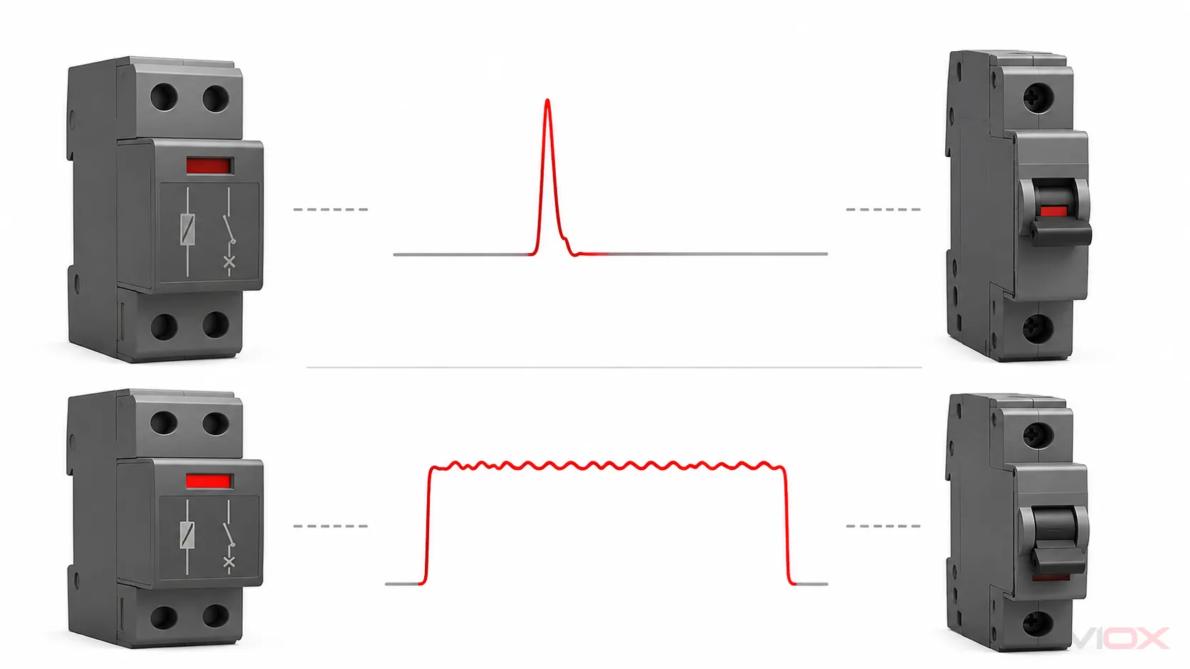
The SPD and breaker watch different electrical conditions.
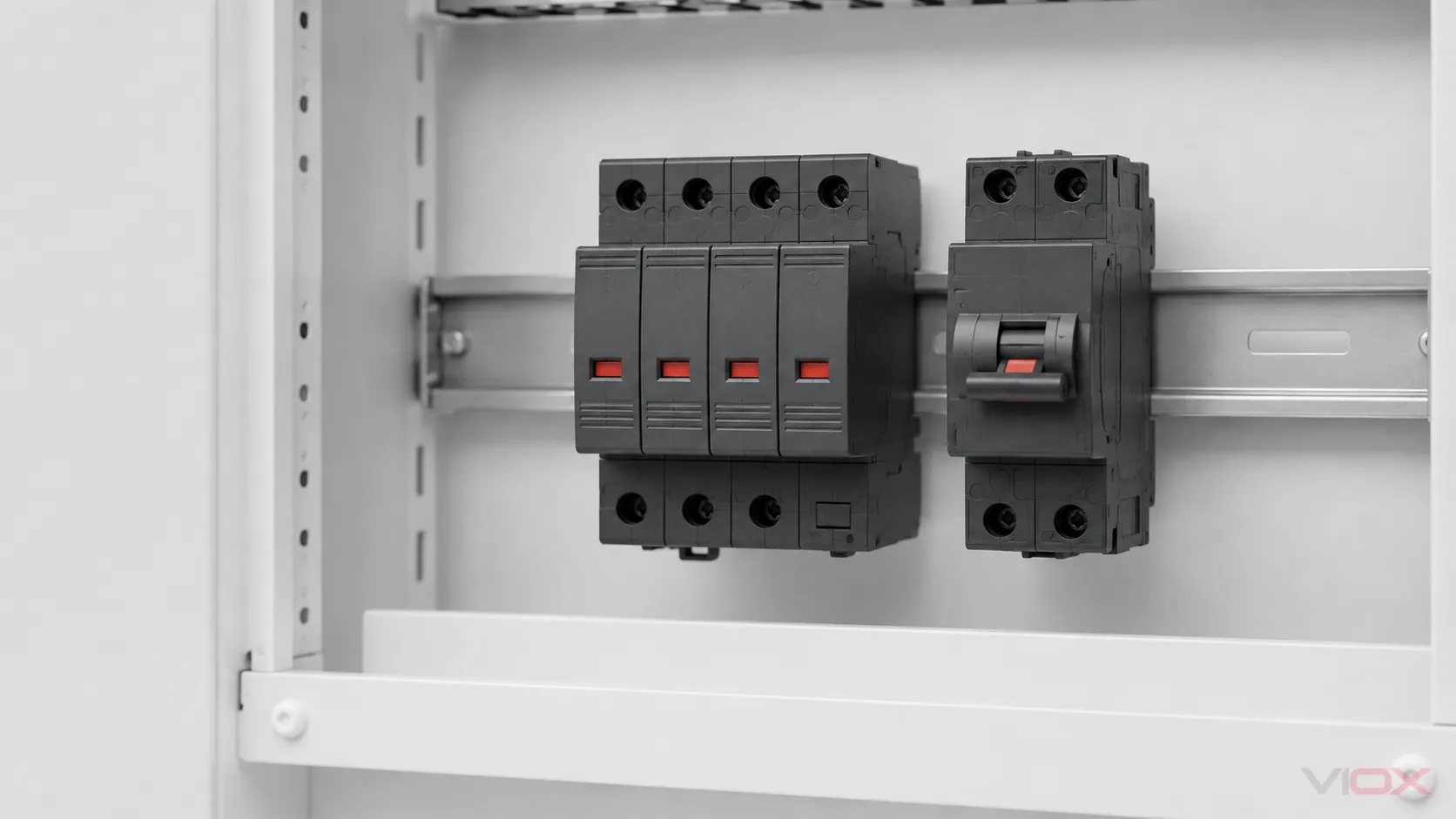
An SPD limits a transient overvoltage by conducting surge current through its designed protection path. A conventional breaker or fuse opens for overcurrent according to its time-current behavior and fault-interruption limits. A microsecond-scale surge event and a sustained fault current are not the same event, even though they can be related in a severe failure.
Many modular SPDs include a thermal or other internal disconnect mechanism. If a protection component degrades and begins heating, that mechanism may isolate the component and change the local indicator or remote contact. Once isolated, it may draw no sustained current that would make the external breaker trip.
This behavior is product-specific. Phoenix Contact, for example, documents particular plug-in varistor products with a thermal disconnect device and green/red local status. DEHN documents plug-in products with a green/red operating/fault window and separate monitoring products with selective alarms. Those examples demonstrate why the exact model matters; they do not establish one universal indicator sequence for all SPDs.
The upstream overcurrent device still has an essential role. NEMA Surge Protection Institute guidance explains that coordinated overcurrent protection is intended to remove an SPD from the distribution system under fault conditions. Depending on SPD design and installation, fault-current protection may be integral, external, or provided by another permitted upstream device. The SPD’s SCCR and the available fault current must also be compatible.
Cause-by-Evidence Diagnostic Matrix
| Possible cause | Why the breaker may remain on | Evidence to check after safe isolation | Correct next step |
|---|---|---|---|
| Normal end-of-life or thermal disconnection of one module | Internal mechanism opens before a sustained external overcurrent develops | Model-specific indicator table, cartridge status, remote contact, event history | Replace the specified cartridge or assembly and investigate why it reached end of life |
| Cumulative MOV aging | Leakage and thermal stress may develop gradually and trigger internal disconnection | Age, surge environment, maintenance history, same-batch conditions | Follow the lifecycle plan; inspect coordinated stages and neighboring poles |
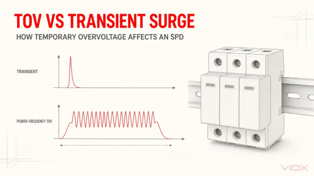
| Temporary or sustained overvoltage | Voltage outside the SPD’s continuous operating capability can stress it without matching the breaker’s overload curve | Supply-voltage records, neutral condition, Uc/MCOV, TOV capability, utility or generator events | Correct the supply/system cause before installing a replacement |
| Wrong Uc/MCOV or system configuration | Normal system voltage or earth/neutral relationship may overstress a protection mode | Nameplate, wiring diagram, earthing system, measured de-energized continuity where authorized | Select a suitable model and correct the design |
| Missing phase, blown internal indication supply, or monitoring fault | Indicator circuit changes while the main breaker remains closed | All pole indicators, auxiliary fuse/contact, manufacturer diagnostic logic | Repair the monitoring/supply issue; do not infer SPD health from one lamp |
| Loose connection, heat, contamination, or water ingress | Local heating or tracking may develop below the upstream trip boundary | Torque records, terminal condition, enclosure seals, thermal or visual damage | Isolate, repair the enclosure/connection cause, and replace damaged components |
| Internal protection operated; external breaker was not required to | Fault was cleared inside the SPD assembly | Product construction and instructions, inspection result | Restore protection exactly as specified |
| External backup fuse opened but a shared/main breaker remains on | A local fuse can isolate the SPD branch independently | Fuse status and approved protective arrangement | Replace only after determining the cause and confirming the permitted fuse |
| Indicator mechanism or replaceable plug is not fully seated | Mechanical status can be wrong or the plug may be disconnected | Seating, coding, base condition, manual | De-energize and correct only as instructed; replace damaged base or plug |
This matrix is a diagnostic shortlist, not a way to declare the cause remotely. A failed status deserves inspection because the circuit may be operating with reduced or no surge protection.
A Safe Stop–Record–Verify Workflow
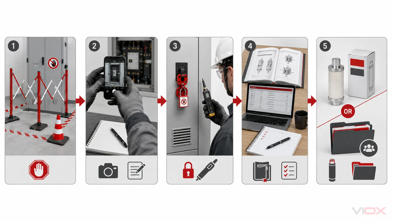
1. Stop and assess visible hazards
Keep the enclosure closed if there are signs of heat, smoke, arcing, moisture, or mechanical damage. Use the facility’s isolation and emergency procedure. An SPD fault is not a reason to improvise energized work.
2. Record the unchanged evidence
Capture the position of every relevant breaker or fuse indicator, each SPD pole window, remote-alarm state, and connected equipment behavior. Note any event timestamp. This evidence helps distinguish one failed cartridge from loss of supply, a local backup fuse operation, or a multi-pole event.
3. Identify the exact protection arrangement
Retrieve the single-line diagram, SPD part number, base and cartridge numbers, installation instructions, upstream or backup protective-device information, system voltage, earthing arrangement, and available fault-current study where applicable.
4. Isolate and verify absence of voltage
A qualified person should use the site’s approved isolation procedure, including lockout/tagout and verification of absence of voltage with suitable equipment. Do not pull a cartridge or tighten a terminal merely because the main breaker appears to be on or off.
5. Inspect the complete system, not only the red module
Check for heat damage, loose conductors, contamination, water ingress, incorrect cartridge coding, damage to the base, operated local fuses, and abnormal indications on other poles or coordinated SPDs. Review supply-quality and remote-monitoring logs where available.
6. Correct the cause before replacement
If Uc/MCOV, system configuration, TOV exposure, enclosure conditions, or backup protection are wrong, a like-for-like replacement can fail again. The TOV versus transient guide covers the sustained-voltage boundary; the SPD wiring guide covers installation verification.
7. Replace and document as specified
Use only a compatible cartridge or assembly. Follow torque, conductor, backup-protection, and test instructions. Record the replacement date, cause finding, parts used, status after restoration, and any changes to the maintenance interval.
What the Breaker Was—and Was Not—Supposed to Do
The upstream breaker is not selected simply to “protect the SPD from surges.” Its duties may include conductor overcurrent protection and clearing an SPD fault under a coordinated arrangement. Whether it is permitted to serve as the SPD’s required backup protection depends on the SPD instructions, connection method, device characteristics, and available fault current.
The breaker may remain closed because:
- the transient ended before its trip boundary was reached;
- an internal thermal disconnect isolated the degraded protective component;
- a local backup fuse opened instead;
- the status circuit reported a fault without a power-circuit short; or
- the indicator reflects a supply/monitoring issue rather than an operated protective component.
Conversely, a breaker can trip if an SPD or its connecting circuit develops fault current within the breaker’s operating range. These outcomes are not proof of correct coordination. The product’s short-circuit current rating, permitted backup device, conductor protection, and available fault current must all be verified.
For the separate question of whether adding an SPD prevents nuisance trips, see does a surge protector prevent tripping circuit breakers?. For an existing-panel connection decision, use can an SPD connect to an existing breaker?.
Do Not Make These “Fixes”
- Do not upsize the breaker or fuse. A larger device can violate the SPD and conductor protection conditions.
- Do not repeatedly reset a tripped device. A fault may still be present.
- Do not bypass the failed pole or alarm. This can leave equipment unprotected and conceal the condition.
- Do not fit a look-alike cartridge. Voltage, Type, coding, protection mode, and base compatibility must match.
- Do not assume a red window is a trophy. It does not prove a surge occurred or that downstream equipment escaped damage.
- Do not megger or high-potential test through a connected SPD unless the approved procedure permits it. Test voltage can make the SPD conduct or be damaged.
- Do not treat a green window as a complete field test. It normally reports only the mechanism designed into that product.
When to Replace One Cartridge—and When to Escalate
Replace a plug-in cartridge only when the manufacturer permits field replacement and the base, adjacent poles, wiring, environment, and root cause have been checked. Replace the complete assembly or escalate the investigation when there is heat damage, carbon tracking, melted plastic, damaged terminals, uncertain base condition, water ingress, repeated failures, unexplained supply voltage, or incompatibility with the available fault current.
In a multi-stage installation, inspect coordinated SPDs after a fault indication. The failed device may be the only visible symptom of a wider event. The SPD lifecycle and MOV aging guide explains maintenance and replacement planning; the SPD status-indicator guide explains common visual and remote indications without treating them as universal.
Evidence to Put in the Maintenance Record
| Record | Why it matters |
|---|---|
| Exact SPD base and cartridge part numbers | Confirms compatibility and indicator logic |
| Indicator state for every pole | Reveals partial loss of protection |
| Upstream breaker and local fuse state | Shows which protective path operated visibly |
| Date, time, weather, switching, generator, or utility event | Supports root-cause correlation without assuming causation |
| System voltage and earthing arrangement | Checks Uc/MCOV and protection-mode suitability |
| Available fault current and SPD SCCR/Iscpv evidence | Confirms fault-current compatibility |
| Enclosure, temperature, moisture, and terminal condition | Identifies environmental or installation stress |
| Replacement part and restored status | Establishes maintenance traceability |
Frequently Asked Questions
Does a red SPD light always mean the MOV is worn out?
No. It often indicates replacement or loss of protection on products designed that way, but color and LED logic are model-specific. It can also reflect another protection component, a supply issue, or a monitoring fault. Read the exact manual.
If the breaker did not trip, is it faulty?
Not necessarily. The event may not have produced sustained current within the breaker’s trip boundary, or an internal/local disconnector may have isolated the SPD first. Correct selection and operation still require separate verification.
Can I keep operating until the next service visit?
The connected load may remain energized, but surge protection may be reduced or absent. Follow the product and site risk procedure. Critical equipment or hazardous damage indicators justify immediate qualified review.
Can I just replace the cartridge?
Only if the manufacturer permits it, the replacement is exactly compatible, the base and wiring are undamaged, and the cause has been checked under safe isolation. Repeated or heat-damaged failures require deeper investigation.
Does the failed indication prove the SPD protected my equipment?
No. It proves only what the product’s status mechanism is designed to report. Without event data and inspection, it does not establish surge magnitude, cause, timing, or downstream outcome.
Technical References
- NEMA Surge Protection Institute — SPD safety and coordinated overcurrent protection
- NEMA Surge Protection Institute — How SPDs work
- Phoenix Contact — example SPDs with thermal disconnect and green/red status
- DEHN — example plug-in SPD with green/red operating and fault indication
- IEC 61643-11:2025 — Low-voltage AC SPD requirements and tests
After the cause, voltage, system configuration, Type, protection modes, and backup-protection requirements are documented, compare VIOX SPD options against the exact application and evidence package.
This is a troubleshooting framework, not permission for energized work. Isolation, inspection, testing, replacement, and re-energization must follow the exact product instructions, site procedures, applicable rules, and qualified electrical review.