On this page
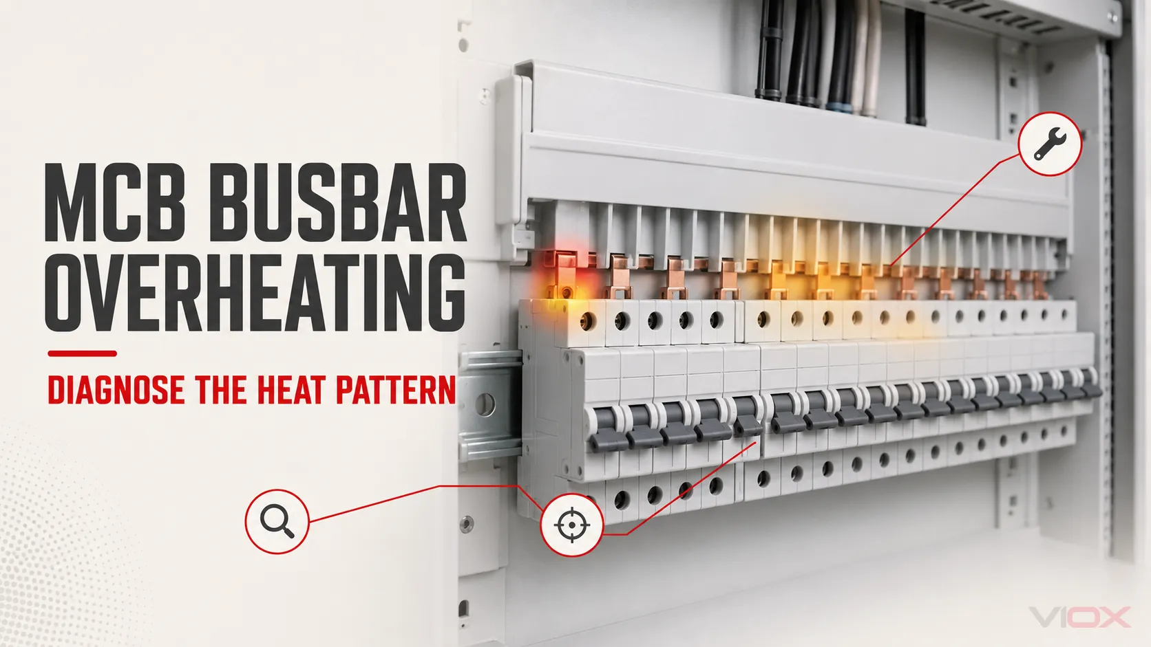
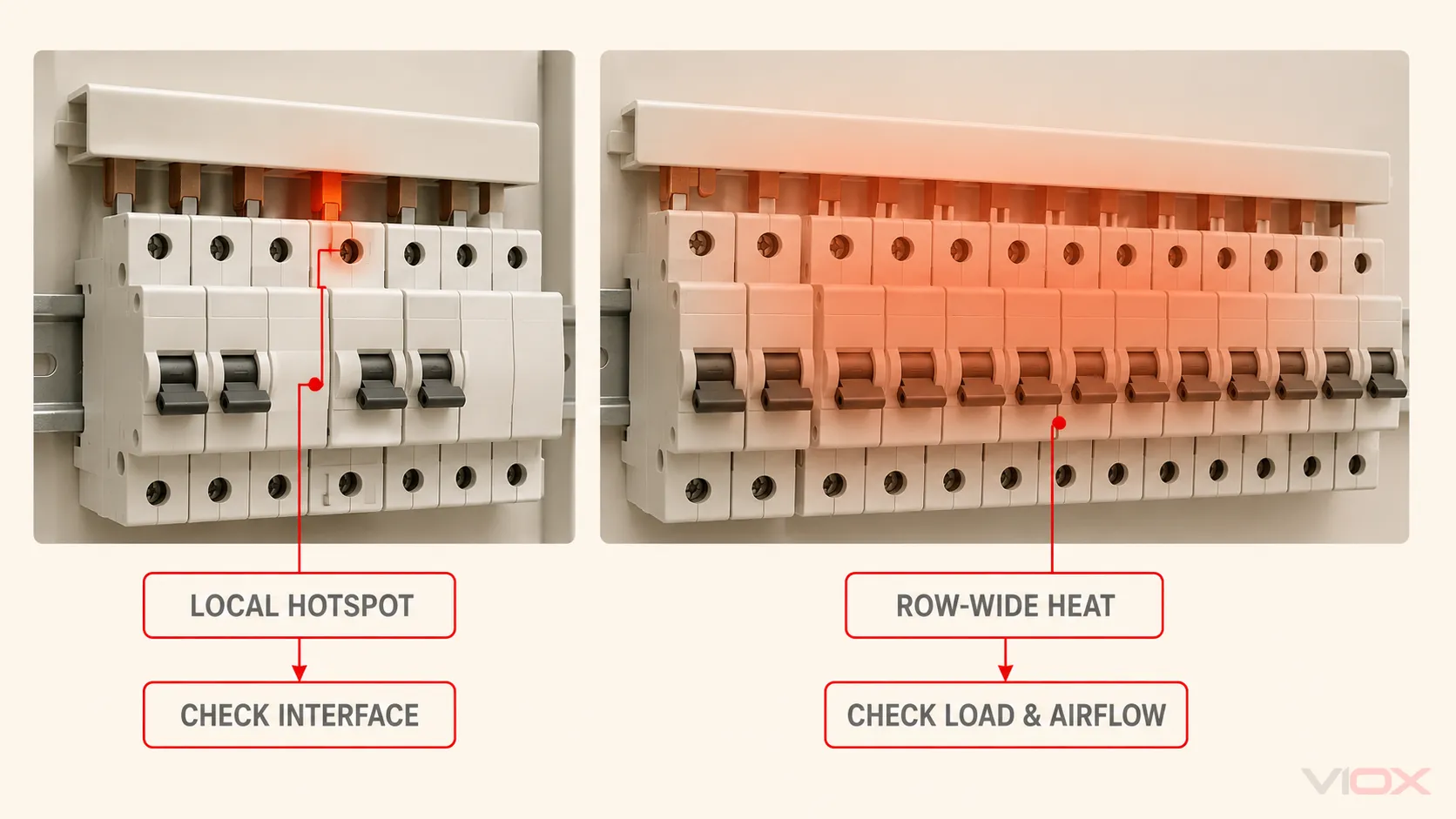
An overheating MCB busbar usually points to one of two conditions: a localized high-resistance connection at one tooth or terminal, or excessive current and poor heat dissipation affecting a larger part of the device row. The heat pattern matters more than any universal temperature number.
Treat burning odor, smoke, softening or charring, visible pitting, repeated tripping, or a temperature that rises rapidly under steady load as stop-use signals. Do not remove a cover, touch a busbar, or tighten a terminal on energized equipment. Isolate the assembly under the applicable safe-work procedure and have a qualified person verify the de-energized state before inspection or service.
Key Takeaways
- A single hot tooth or terminal directs the diagnosis toward seating, clamping, contamination, conductor termination, or device damage.
- Similar heating across several devices directs the diagnosis toward load, busbar rating, grouping, enclosure temperature, or ventilation.
- A thermal image is evidence of a pattern, not a diagnosis by itself. Load, emissivity, reflected temperature, and comparison conditions all affect interpretation.
- There is no safe universal torque value for every MCB and comb busbar. Use the exact device and busbar instructions, the specified tool, and the stated connection arrangement.
- Heat-damaged plastic, pitted contacts, loss of spring pressure, or a deformed comb tooth usually changes the task from “retighten” to “replace and investigate the cause.”
Quick Diagnosis: Match the Heat Pattern to the Next Check
| What you observe | Most useful next check | What the result may indicate | Bounded next action |
|---|---|---|---|
| One busbar tooth or one MCB terminal is hotter than comparable loaded poles | Compare loading, then inspect the exact interface after isolation | Incomplete seating, wrong terminal geometry, incorrect clamping, contamination, a damaged tooth, or an internal device problem | Correct only with approved components and exact instructions; replace damaged parts |
| The incoming end of the comb busbar is hottest and heat reduces along the row | Verify measured current and the approved feed arrangement | High current near the feed point, unsuitable feed location, or a rating/application mismatch | Check the manufacturer’s busbar and device-row design data; redesign if the arrangement is outside it |
| Several adjacent devices are similarly warm | Compare circuit loads, enclosure ambient, grouping, and ventilation | Sustained loading, heat transfer from neighboring devices, or restricted dissipation | Reduce load if required and verify the assembly design rather than tightening random terminals |
| The breaker body is hot but its busbar interface is not the thermal center | Check actual load and the breaker’s line/load connections and behavior | Overload, downstream termination issue, ambient influence, or an internal breaker fault | Follow the breaker manufacturer’s troubleshooting path; replace the breaker if damage or an internal fault is confirmed |
| Discoloration, odor, softened insulation, pitting, or charring is present | De-energized visual inspection of the complete affected zone | Thermal damage has progressed beyond a simple temperature anomaly | Keep de-energized; identify the cause and replace affected components as required |
| A thermal image looks abnormal only on shiny metal | Repeat with controlled settings and a valid comparison surface | Low emissivity or reflected energy may be distorting the apparent temperature | Have a trained thermographer verify the measurement before making a replacement decision |
The Five-Stage MCB Busbar Overheating Diagnostic Path
1. Screen for conditions that require immediate isolation
Start with what can be observed without approaching exposed energized parts. Escalate immediately if there is smoke, a burning smell, crackling, repeated or unexplained tripping, visible melting, charring, pitting, or rapid worsening.
A warm enclosure or breaker is not automatically a failed busbar. Conversely, a modest-looking thermal image does not prove the connection is safe. The first decision is whether the equipment can remain in service long enough for a planned qualified inspection—not whether a generic temperature limit has been crossed.
2. Record the operating context before disturbing the assembly
A useful diagnosis needs context:
- Which circuits were operating?
- Was the load steady, cyclic, unbalanced, or recently changed?
- Is one pole abnormal compared with equivalent poles under similar load?
- Is the hot area centered on the comb tooth, the MCB terminal, the conductor terminal, or the device body?
- Has a breaker, comb busbar, conductor, or enclosure component recently been replaced?
- Are the busbar family, pitch, pole arrangement, terminal style, and device series documented as compatible?
Photographs, load readings, thermal images, model numbers, and the time of observation make later comparison possible. For energized measurement or thermography, use a qualified person following the site’s electrical safe-work program and the applicable local rules.
3. Separate localized contact heating from system-wide heating
At a resistive interface, heat production increases with both current and resistance:
P = I²RThe formula explains why a small deterioration at a contact can become visible under load. It does not identify the cause by itself. The extra resistance might come from incomplete tooth engagement, incorrect terminal geometry, inadequate or excessive clamping, contamination, corrosion, a damaged contact surface, a poorly terminated conductor, or a failing breaker connection.
A localized thermal center at one connection therefore makes the interface the first inspection target. A broad temperature rise across a device row makes load, busbar application rating, grouping, enclosure ambient, and heat dissipation more plausible first branches.
This distinction also protects the cluster boundary: for installation fit and verification, use the MCB busbar installation mistakes guide; for the deeper physics of large bolted copper joints, use the copper busbar joint overheating guide.
4. Isolate, verify de-energization, and inspect the exact interface
Electrical service work must follow the applicable national rules, employer procedure, equipment instructions, and risk assessment. In the United States, OSHA guidance requires isolation and verification of de-energization before service work; other markets have their own legal and procedural requirements.
After a qualified person has established a safe work condition, inspect the affected interface rather than tightening the entire row by habit:
- Record the exact MCB and busbar identifiers.
- Confirm that the comb profile and tooth geometry are approved for the device terminal.
- Check whether the tooth entered the intended clamp rather than sitting beside, behind, or only partly inside it.
- Look for pitting, erosion, loss of plating, contamination, corrosion, deformation, softened insulation, and carbonized material.
- Inspect the corresponding conductor termination and adjacent devices because the visible hot point may be receiving heat from another connection.
- Compare the installed conductor, feed arrangement, busbar rating, and device row with the manufacturer’s documentation.
Do not use a generic “residential MCB torque” range. Published terminal settings differ across product families and connection designs. Use the value, bit, conductor arrangement, and method specified for the exact model. Over-tightening is not a safety margin; it can damage a clamp, thread, housing, or contact geometry.
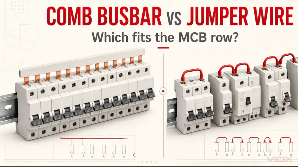
If the busbar and breaker were not documented as compatible, use the MCB busbar compatibility guide before selecting replacement parts. If the row needs a different pitch, phase arrangement, current rating, or feed method, use the MCB and comb busbar selection guide.
5. Correct the cause, then verify the result under controlled conditions
The repair must address the diagnosed cause—not merely make the terminal feel tighter.
- Incorrect seating or incompatible geometry: replace or reconfigure the components using an approved combination.
- Incorrect tightening: inspect for damage, then remake the connection with the exact manufacturer procedure and a suitable calibrated tool.
- Contamination or corrosion: follow the component manufacturer’s permitted cleaning or replacement method. Do not improvise abrasive preparation or joint compound on a miniature device connection unless the instructions require it.
- Damaged tooth, clamp, breaker, or insulation: replace the affected component and inspect adjacent parts exposed to heat.
- Excessive current or unsuitable arrangement: correct the load, feed method, busbar rating, device grouping, or enclosure thermal design.
- Suspected internal breaker problem: follow the breaker manufacturer’s diagnostic and replacement guidance.
Before return to service, verify guards, end caps, clearances, conductor restraint, terminal condition, and device operation. A qualified person should then compare the repaired assembly under a representative, controlled load with the recorded baseline. A repair is not complete if the same localized pattern returns.
How to Interpret Thermal Images Without a False Threshold
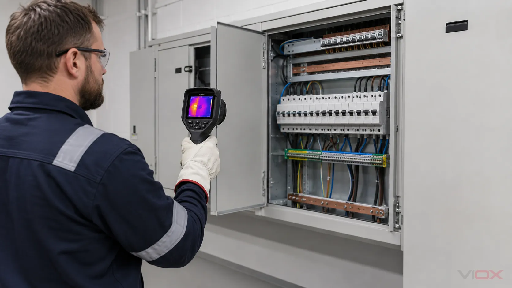
Thermography is valuable because it shows spatial differences before damage is obvious. Its strongest use here is comparative:
- compare equivalent poles or devices carrying similar loads;
- compare the same connection at similar operating conditions over time;
- record load, ambient conditions, camera settings, distance, and viewing angle;
- confirm whether the apparent hot area aligns with the metal interface, conductor terminal, or breaker body;
- investigate a significant change instead of assigning one universal pass/fail temperature.
Shiny copper and other polished metals have low emissivity and can reflect thermal energy from surrounding objects. A bright or cool patch may therefore represent the measurement conditions rather than the component temperature. FLIR advises accounting for emissivity and reflected temperature and notes that accurate measurement of difficult low-emissivity surfaces requires appropriate technique and training.
Do not copy temperature-rise limits from a different breaker family, terminal material, product standard, or assembly and apply them to every MCB busbar. Acceptable temperature rise depends on the exact equipment, reference point, material, loading, ambient conditions, and governing product documentation.
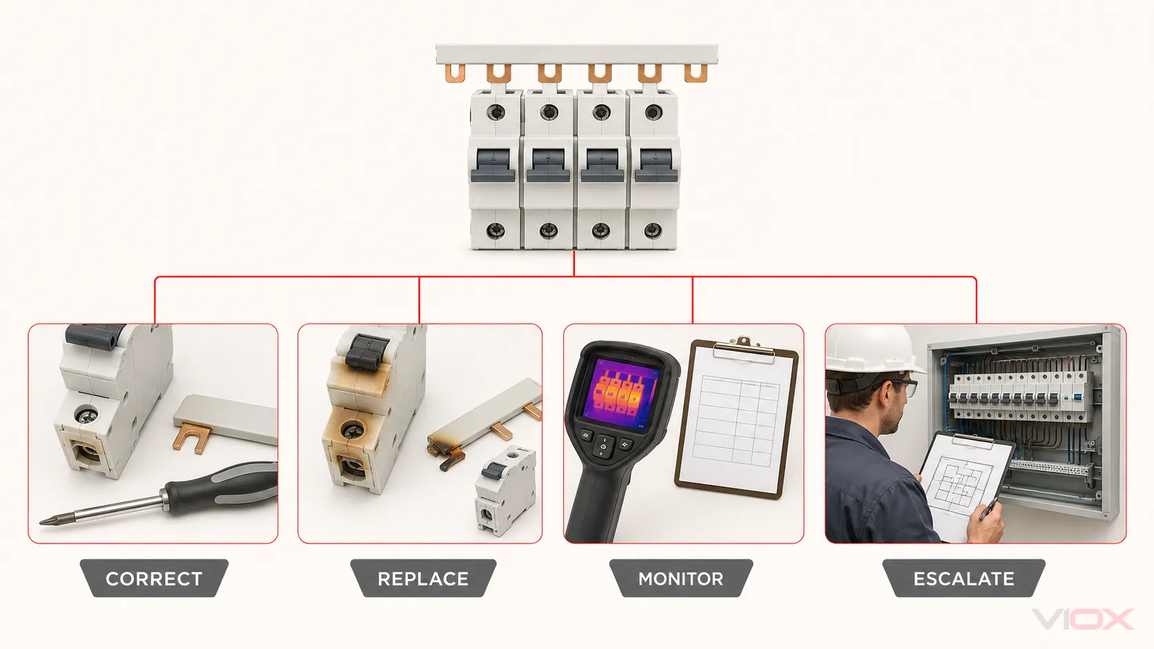
Correct, Replace, Monitor, or Escalate?
| Disposition | Use it when | Do not use it when |
|---|---|---|
| Correct and verify | No thermal damage is found, the cause is confirmed, and the exact manufacturer procedure permits the connection to be remade | Compatibility is uncertain or the contact system is damaged |
| Replace affected components | There is pitting, deformation, loss of contact pressure, damaged plating, cracked/softened insulation, charring, or manufacturer guidance requires replacement after severe heating | The diagnosis has not yet identified what caused the damage |
| Monitor against a baseline | The assembly is within its documented application, no damage is present, comparable loaded components behave similarly, and a qualified review finds no actionable defect | There is odor, rapid change, repeated tripping, visible damage, or an unexplained localized hotspot |
| Escalate for engineering review | The row loading, feed arrangement, enclosure thermal design, fault history, or equipment coordination is uncertain | A simple documented component correction fully resolves the issue and verification passes |
Preventing the Same Hotspot from Returning
Prevention is a controlled specification and verification process:
- Document compatibility. Record breaker series, terminal type, comb profile, pitch, pole/phase arrangement, busbar rating, and approved accessories.
- Follow exact connection instructions. Record the specified tightening value and tool for the exact device and connection; do not rely on memory or a cross-brand rule.
- Inspect the complete current path. A hot comb tooth may originate from the busbar interface, the breaker, the conductor terminal, or an application mismatch.
- Keep a commissioning baseline. Save load and thermal records taken under known conditions so future surveys have a valid comparison.
- Define condition-based inspection triggers. Load changes, device replacement, nuisance tripping, odor, discoloration, contamination, water exposure, or abnormal thermal patterns should trigger review. The maintenance interval should come from the equipment documentation and site maintenance program, not a universal calendar rule.
- Use suitable replacement parts. When replacement is required, compare documented MCB busbar product options against the installed device family and application rather than selecting by tooth spacing alone.
For a complete orientation to terminology and busbar types, see Circuit Breaker Busbar Explained. If a comb busbar must be shortened, keep that work within the separate comb busbar cutting and insulation procedure.
Frequently Asked Questions
How hot is too hot for an MCB busbar?
There is no universal temperature that applies to every MCB, terminal, comb busbar, enclosure, load, and measurement point. Use the exact manufacturer limits and applicable product/assembly requirements. In the field, an unexplained localized difference from comparable connections under similar load, a rapid change from baseline, or any odor, discoloration, softening, pitting, or tripping behavior warrants investigation.
Should I retorque every MCB if one connection is hot?
Not automatically. First identify the thermal center and the cause. Some manufacturer maintenance guidance specifically cautions against disturbing connections that show no evidence of overheating or looseness. Inspect the affected interface and follow the exact model instructions; indiscriminate retightening can introduce new damage or mask an incompatible connection.
Can a thermal camera prove that a terminal is loose?
No. It can reveal a temperature pattern consistent with abnormal resistance, but it cannot prove the mechanical cause. Confirm the load, measurement conditions, emissivity, reflected temperature, seating, compatibility, terminal condition, and device behavior.
Can a discolored MCB busbar be reused?
Do not decide from color alone, but treat heat-related discoloration, pitting, deformation, damaged plating, or softened insulation as evidence requiring qualified inspection. Manufacturer guidance for affected breaker and bus connections may require replacement when severe heating or contact damage is present. Replace every component required by the exact equipment instructions and correct the cause before re-energization.
Sources
- OSHA: verification of isolation and de-energization before service
- Schneider Electric: troubleshooting thermal-magnetic breaker tripping and overheated connections
- Schneider Electric: using thermal scans of circuit breakers
- Schneider Electric: field testing and maintenance guidance for circuit breakers and connections
- Schneider Electric: product-family torque settings for ACB, MCCB, and MCB equipment
- Hager UK: device-specific tightening torque support table
- FLIR: emissivity and reflected-temperature effects in thermal imaging
If you are specifying replacement MCB busbars for a documented breaker series and device row, send the model numbers, terminal drawings, phase arrangement, current requirement, and quantity to [email protected] for compatibility review.