Quick Answer: What Is a Circuit Breaker Busbar?
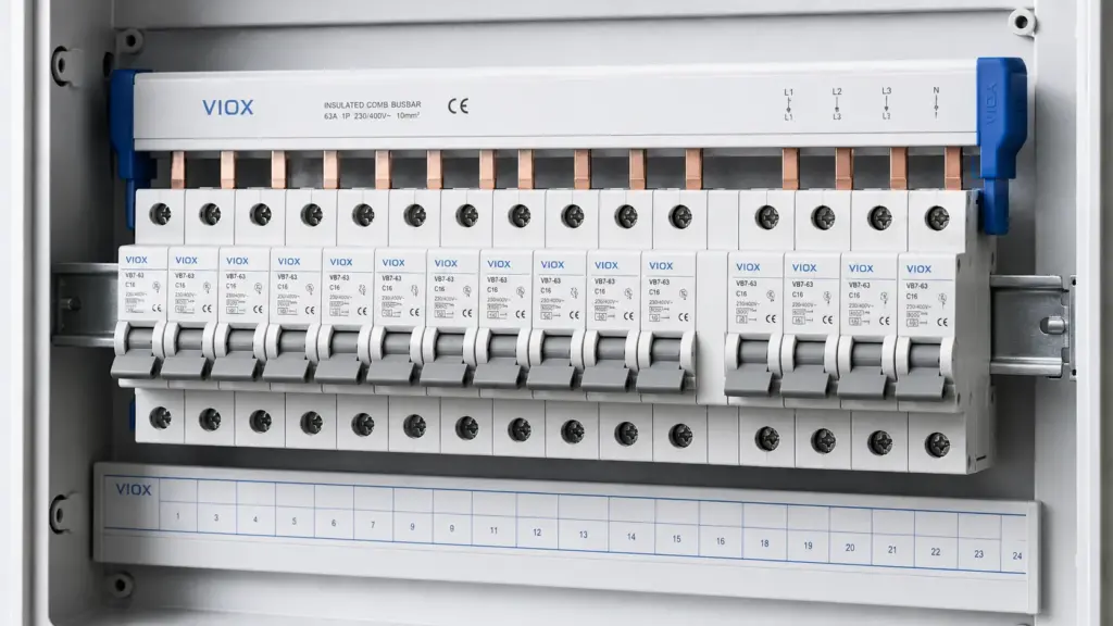
A circuit breaker busbar is a conductive metal bar used to distribute power to multiple circuit breakers in a panel or distribution board. In modular electrical panels, this usually refers to an MCB busbar, also called a comb busbar, pin busbar, fork busbar, or breaker link bar.
Instead of wiring each miniature circuit breaker (MCB) with separate jumper wires, a busbar feeds several breakers through a common copper conductor. This makes the panel cleaner, reduces wiring time, improves phase organization, and helps avoid loose jumper connections when the busbar is correctly matched to the breaker terminals.
The important point is compatibility. A busbar must match the breaker brand or terminal design, pole spacing, phase arrangement, rated current, voltage, and short-circuit conditions of the panel. A busbar that physically fits is not automatically safe or approved for the installation.
Circuit Breaker Busbar Terms at a Glance
| Term | What It Means | Typical Use |
|---|---|---|
| Circuit breaker busbar | Conductive bar used to distribute power to multiple breakers | Distribution boards, control panels, modular breaker rows |
| MCB busbar | Comb-style busbar designed for modular MCBs | DIN rail consumer units and panel boards |
| Common busbar | Shared conductor feeding several circuits or devices | Panel distribution and common supply connections |
| Breaker link bar | Another name for a busbar linking multiple breakers | Modular breaker rows |
| Panel busbar | Main busbar inside a breaker panel or switchboard | Larger power distribution assemblies |
| Fork busbar | Busbar with fork-shaped terminals | Some screw-clamp breaker terminals |
| Pin busbar | Busbar with pin-shaped terminals | Many modular breakers and distribution boards |
For product evaluation, VIOX provides MCB busbar options for modular distribution applications.
How an MCB Busbar Works
An MCB busbar distributes incoming power across a row of circuit breakers. In a typical modular distribution board, the busbar is installed on the supply side of a group of MCBs, RCCBs, or RCBOs, depending on the panel design and device compatibility.
The busbar teeth or pins insert into the breaker terminals. When the breaker terminal screws are tightened according to the manufacturer’s instructions, the busbar becomes a common feed conductor for multiple protective devices.
This arrangement can replace multiple short jumper wires. The benefits are practical:
- cleaner wiring layout
- fewer individual loop wires
- faster panel assembly
- more consistent phase distribution
- reduced risk of loose handmade jumpers
- easier visual inspection when covers and end caps are fitted correctly
However, the busbar does not replace breaker protection. Each circuit still needs the correct protective device, cable size, load rating, and installation method.
Circuit Breaker Busbar vs Common Busbar vs Panel Busbar
These terms are related but not identical.
| Feature | Circuit Breaker / MCB Busbar | Common Busbar | Panel Busbar |
|---|---|---|---|
| Main purpose | Link multiple modular breakers | Provide a shared electrical connection | Carry main power inside a panel or switchboard |
| Typical size | Small to medium | Small to large | Medium to large |
| Common form | Comb, pin, fork, insulated bar | Copper or aluminum bar | Copper or aluminum main conductor |
| Installation point | DIN rail breaker row | Depends on equipment | Main panel assembly |
| Main risk | Device incompatibility or poor seating | Overload or incorrect bonding | Fault current and thermal design |
For this article, the main focus is the circuit breaker busbar used with modular breakers, especially MCB busbars.
Pin-Type Busbar vs Fork-Type Busbar
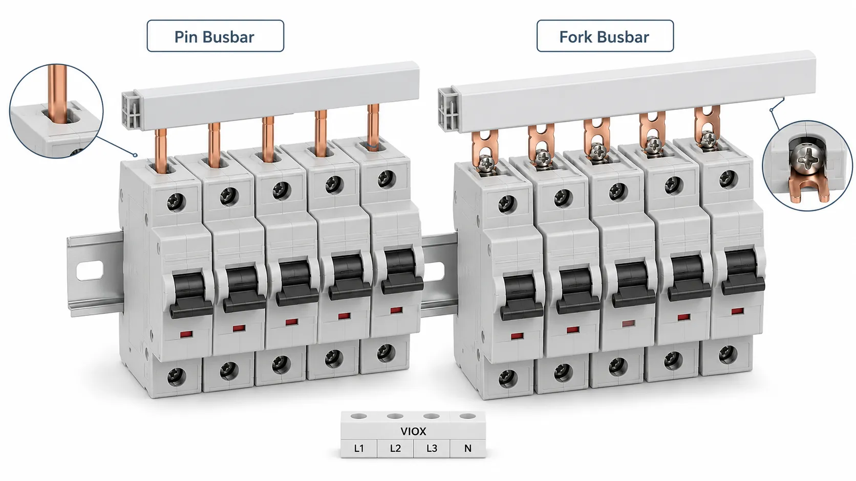
The two common forms for modular breakers are pin busbars and fork busbars.
Pin-Type Busbar
A pin-type busbar has straight pins that enter the breaker terminal. It is common in many modular breaker systems. The pin must sit fully inside the terminal clamp and align correctly with each breaker.
Pin busbars are often used when:
- the breaker terminal is designed for pin entry
- the panel uses modular MCBs on DIN rail
- the installer needs a compact, clean distribution row
- the busbar must be cut to match the number of breaker poles
Fork-Type Busbar
A fork-type busbar has fork-shaped teeth that fit around or under the terminal screw or clamp area, depending on the breaker design. It is used only where the breaker terminal is designed to accept that shape.
Fork busbars are often used when:
- the breaker terminal clamp is compatible with fork teeth
- the manufacturer allows fork busbar connection
- the installation requires strong mechanical seating under a screw-clamp terminal
Never assume a fork busbar can replace a pin busbar. The terminal geometry is different. Using the wrong type can create poor contact, overheating, or arcing.
1P, 2P, 3P, and 4P Busbar Types
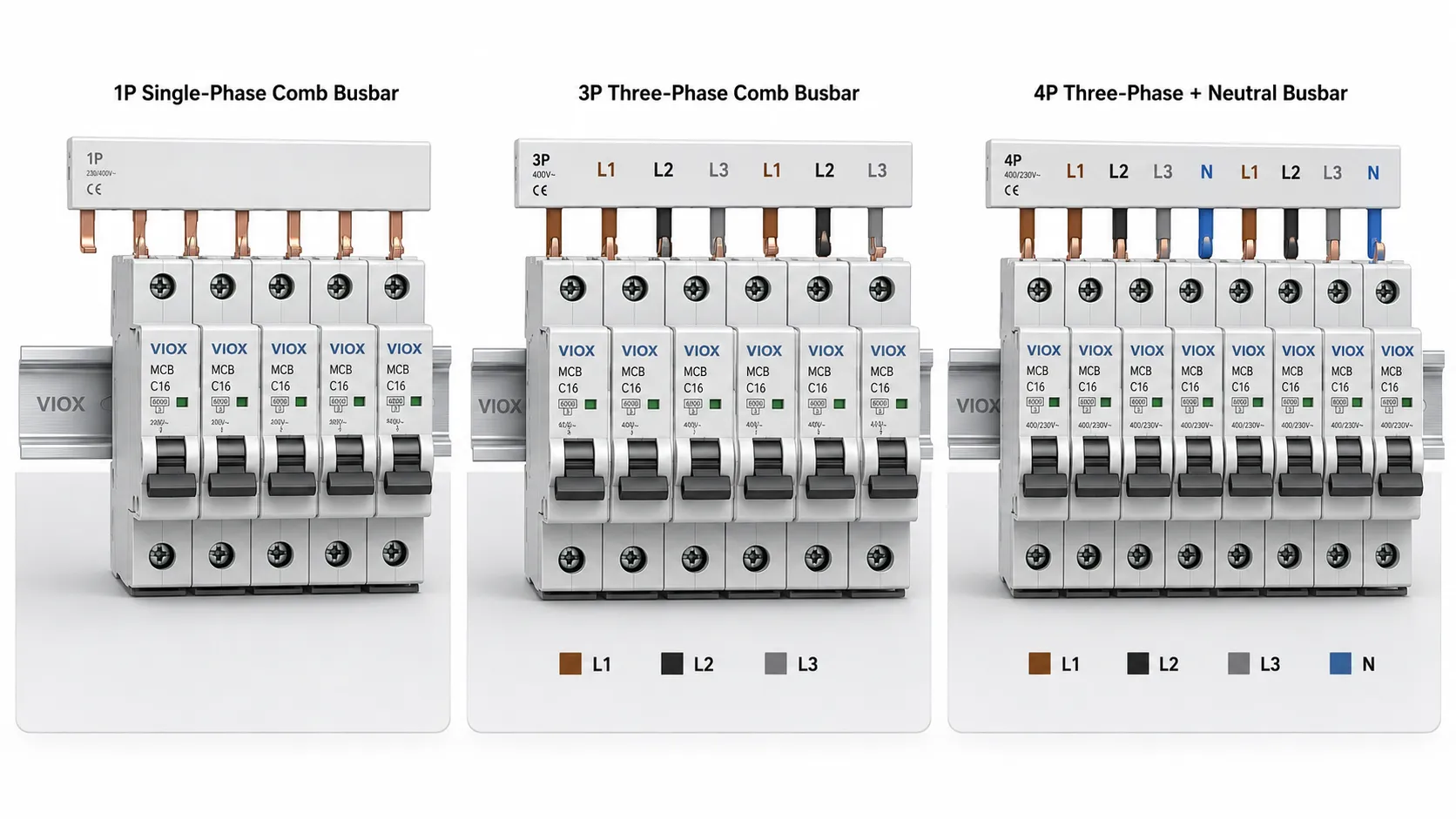
Circuit breaker busbars are also selected by pole arrangement.
| Busbar Type | Typical Use | What to Check |
|---|---|---|
| 1P busbar | Single-phase breaker rows | Current rating, breaker spacing, terminal type |
| 1P+N busbar | Single-phase phase-and-neutral distribution | Neutral arrangement and device compatibility |
| 2P busbar | Two-pole devices or split arrangements | Pole spacing and phase/neutral layout |
| 3P busbar | Three-phase MCB distribution | Phase sequence L1/L2/L3 and tooth pitch |
| 4P busbar | Three-phase plus neutral systems | Neutral position, RCCB/RCBO compatibility, panel design |
For three-phase systems, phase sequence matters. A 3P busbar usually repeats L1, L2, and L3 across the breaker row. A 4P busbar may include a neutral path, but the exact arrangement depends on the system and device design.
How to Choose a Busbar for MCB, RCCB, or RCBO
Selecting a busbar is not only about current rating. The busbar must be mechanically and electrically compatible with the devices in the panel.
| Selection Factor | Why It Matters |
|---|---|
| Breaker series compatibility | Different brands and models may have different terminal geometry |
| Pin or fork type | Must match the breaker terminal design |
| Pole spacing | The busbar pitch must match the modular device spacing |
| Number of poles | 1P, 2P, 3P, or 4P must match the circuit arrangement |
| Rated current | Must be suitable for the expected feed current |
| Rated voltage | Must match the distribution system voltage |
| Short-circuit withstand | Must fit the panel’s fault level and upstream protection design |
| Insulation and touch protection | Reduces accidental contact risk during installation and maintenance |
| End caps and covers | Required to cover exposed cut ends and live parts |
| Cut-to-length rules | Cut surfaces must be protected according to manufacturer instructions |
If the breaker row includes different device types, such as MCBs, RCCBs, and RCBOs, verify compatibility carefully. Devices may have different terminal depths, neutral positions, or line/load orientation.
VIOX also supplies adjacent modular protection devices such as MCBs, RCCBs, and RCBOs for complete distribution board configurations.
Circuit Breaker Busbar Connection Rules
The safest connection rule is simple: follow the breaker and busbar manufacturer’s wiring diagram. Do not decide by appearance alone.
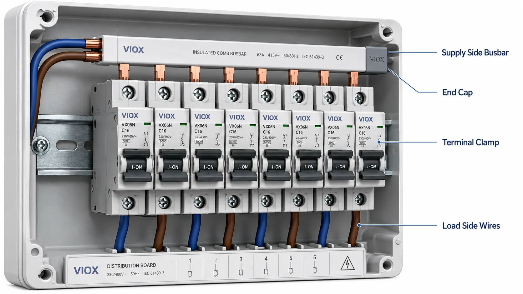
In many distribution boards, the busbar is used on the supply side of the breaker row to distribute incoming power. The outgoing load conductors are then connected to the load side of each breaker. But this is not universal. Some products may have different line/load markings or special feed arrangements.
Before energizing the panel, check:
- breaker terminal markings
- busbar tooth seating
- screw tightening according to product instructions
- end cap installation
- insulation cover placement
- correct phase sequence
- no exposed live cut ends
- no mismatch between pin/fork busbar and terminal type
- no mixed devices that disturb alignment
- no loose or tilted breaker caused by busbar pressure
If an RCCB or RCBO is included, also verify neutral routing. A neutral connection error can cause nuisance tripping, no tripping, or unsafe operating conditions.
Common Installation Mistakes
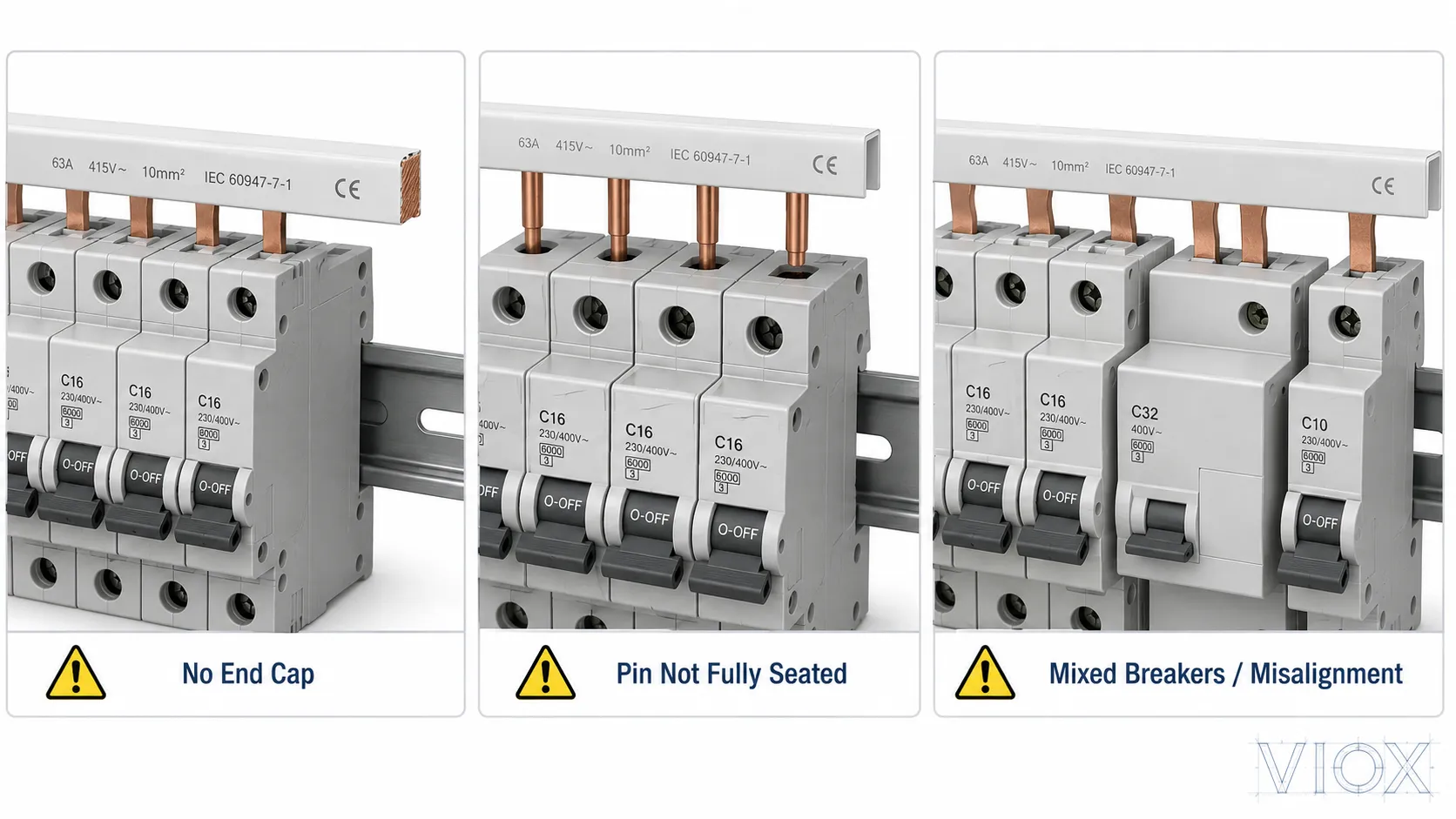
Mistake 1: Using the Wrong Busbar Type
A pin busbar and a fork busbar are not interchangeable unless the device manufacturer specifically allows it. Wrong geometry can create partial contact. Partial contact creates heat.
Mistake 2: Mixing Incompatible Breakers
Two modular breakers may both be 18 mm wide, but their terminals may not align at the same depth. Mixing brands or product families can cause a busbar to sit unevenly.
Mistake 3: Leaving Cut Ends Exposed
Cut-to-length busbars must be finished with proper end caps or insulation covers. Exposed copper at the end of a busbar is a shock and short-circuit hazard.
Mistake 4: Feeding the Wrong Side of the Breaker
Some installers assume the busbar always belongs on the top or always belongs on the bottom. The correct side depends on the device marking and panel design. Always follow the line/load markings and manufacturer instructions.
Mistake 5: Replacing a Busbar With Short Cable Jumpers
Short jumper wires may look convenient, but they can introduce inconsistent tightening, poor bending, crowded terminals, and overheating. If a panel is designed for a busbar system, use the correct busbar and accessories.
Mistake 6: Ignoring Heat Marks
Discoloration, melted insulation, a burnt smell, or repeated breaker tripping near a busbar connection can indicate poor contact or overload. The panel should be de-energized and inspected by a qualified person.
Safety Checks Before Energizing
| Check | What to Confirm |
|---|---|
| Mechanical fit | Busbar sits straight, no tilted breakers |
| Terminal clamping | All busbar teeth are fully seated and tightened |
| Insulation | Covers and end caps are installed |
| Phase order | Three-phase sequence is correct |
| Neutral routing | RCCB/RCBO neutral path is correct |
| Current rating | Busbar rating matches the feed arrangement |
| Fault rating | System design accounts for prospective short-circuit current |
| Device compatibility | Breakers and busbar belong to a compatible system |
| Final inspection | No exposed copper, loose parts, or damaged insulation |
For switchboard and distribution board projects, the complete assembly may also need to meet local code requirements and applicable low-voltage assembly standards. The busbar alone does not make the panel compliant.
Why Busbar Compatibility Matters
An MCB busbar may look like a simple copper strip, but its geometry controls contact quality. The tooth thickness, pitch, insulation profile, copper section, end cap design, and terminal seating all affect performance.
Poor compatibility can cause:
- localized heating
- arcing at breaker terminals
- nuisance tripping from heat transfer
- damaged insulation
- loose breaker alignment
- unreliable supply to downstream circuits
This is why serious panel builders do not choose a busbar only by current rating. They check the full breaker-busbar system.
FAQ
What is a circuit breaker busbar?
A circuit breaker busbar is a conductive bar that distributes power to multiple circuit breakers. In modular panels, it is often a comb-style MCB busbar used to link several breakers in one row.
What is the difference between a busbar and a circuit breaker?
A busbar distributes electrical power. A circuit breaker protects a circuit by opening during overload or short-circuit conditions. They often work together, but they do different jobs.
What is an MCB busbar?
An MCB busbar is a comb-style busbar designed to feed multiple miniature circuit breakers in a distribution board. It can be pin-type, fork-type, single-phase, or multi-phase depending on the system.
Can I use any busbar with any breaker?
No. The busbar must match the breaker terminal design, pole spacing, rating, and manufacturer’s compatibility requirements. A busbar that physically fits may still be electrically or mechanically unsuitable.
Is a pin busbar better than a fork busbar?
Neither is universally better. Pin and fork busbars serve different terminal designs. The correct choice is the type approved or recommended for the breaker series being installed.
Where does the busbar connect on an MCB?
In many distribution boards, the busbar connects to the supply side of the MCB row, but this depends on the breaker design and panel wiring diagram. Always follow line/load markings and manufacturer instructions.
Can a busbar be cut to length?
Many MCB busbars can be cut to length, but the cut end must be protected with a proper end cap or insulation cover. Follow the busbar manufacturer’s instructions.
Why does a breaker busbar get hot?
Common causes include loose terminal screws, poor seating, wrong busbar type, overload, mismatched breaker compatibility, or damaged insulation. Heating at a busbar connection should be investigated before continued operation.
Conclusion
A circuit breaker busbar is a practical way to distribute power across multiple breakers, especially in MCB distribution boards and modular DIN rail panels. It saves wiring time, improves layout, and reduces the need for many separate jumper wires.
The key is not simply choosing a busbar with enough current rating. The busbar must match the breaker terminal type, pole spacing, phase arrangement, voltage, current, short-circuit conditions, and insulation requirements. For safe and reliable distribution boards, treat the busbar and breaker row as one connected system rather than separate parts.
