

On this page
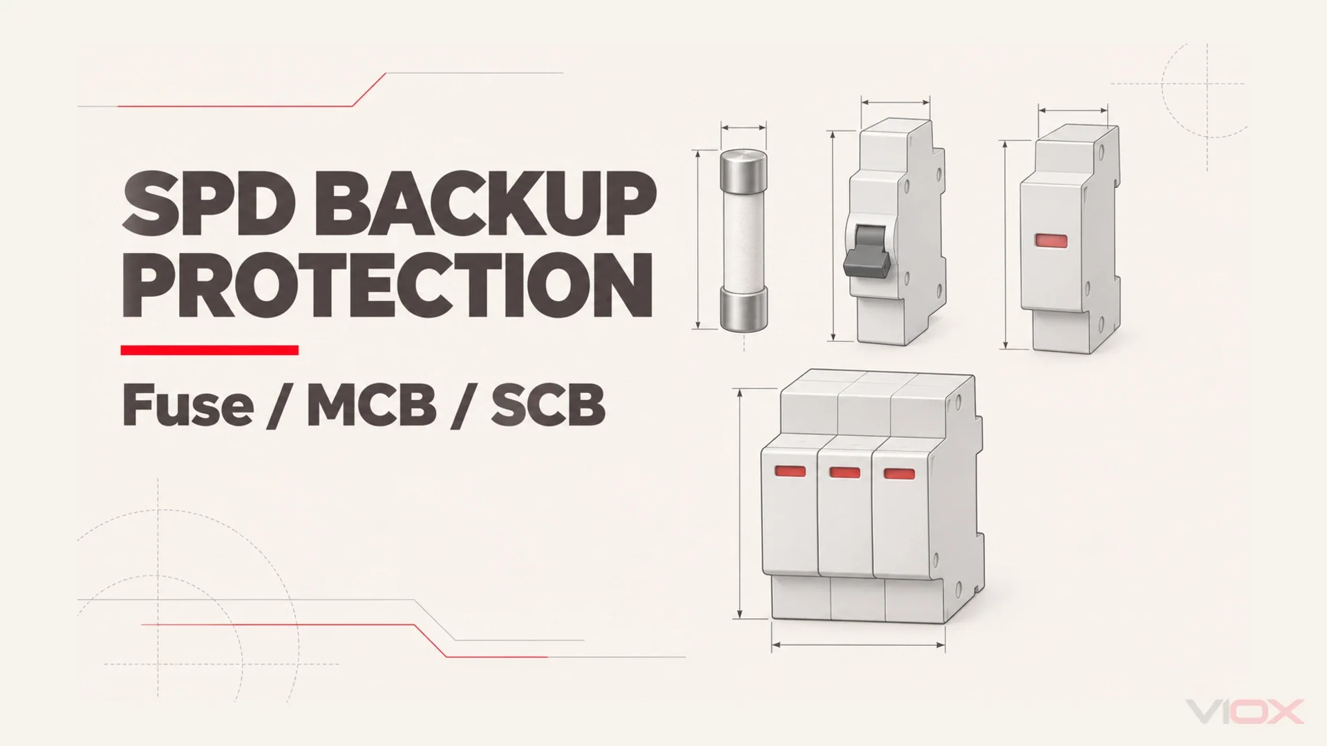
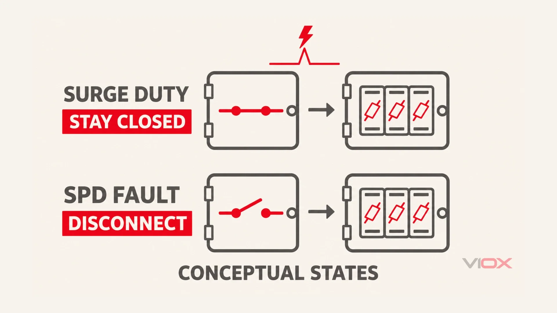
Choose SPD backup protection from the surge protective device manufacturer’s documented combination, not from the SPD’s surge-current rating alone. A gG fuse, miniature circuit breaker (MCB), or dedicated SPD backup disconnector (often marketed as an SCB) must satisfy two duties: remain available through the specified surge and safely disconnect an SPD fault. Check the permitted device type and ampere limit, the installation’s available fault current, and the combination’s conditional short-circuit rating separately. No universal conversion turns SPD kA into fuse or breaker amperes.
This guide addresses AC power SPDs for panel builders, installers and electrical engineers. Whether an existing breaker can provide the required function is a separate decision covered in Can I Connect a Surge Protector to an Existing Breaker?.
Why an SPD Needs Backup Protection
During a surge, an SPD diverts impulse current and limits voltage. At end of life, a metal-oxide varistor (MOV) can deteriorate into a low-resistance state. Supply-frequency current can then flow through a component that was not intended to carry that sustained fault. This is one possible failure condition, not the only way an SPD can fail.
The backup arrangement clears that fault or provides the specified disconnection function. It does not replace the SPD’s voltage-limiting function or protect equipment by tripping fast enough to stop the lightning impulse.
An internal thermal disconnector and an external short-circuit protective device also have different jobs. Thermal separation can address an overheating component; do not assume it can interrupt the installation’s available short-circuit current. Some SPDs integrate the required fault protection, while others depend on specified upstream or branch protection. Read the exact instructions before adding or omitting a device.
Two opposing errors matter. A backup device that operates unnecessarily during a surge can disconnect the SPD branch while the load continues running. A device that cannot clear the SPD fault can leave dangerous heating or arcing. The correct combination must avoid both outcomes within its declared conditions. IEC 61643-12 provides the selection and application framework, including disconnecting-device considerations.
The Three Options, Compared
| Option | Practical benefit | Limitation to resolve | Evidence needed before selection |
|---|---|---|---|
| gG fuse | Available with high breaking capacity; often a simple, economical arrangement | Replacement after operation; impulse withstand and fuse class must suit the SPD | Manufacturer’s permitted fuse class/rating and conditional short-circuit data |
| MCB | Familiar equipment with resettable operation and visible handle state | Instantaneous and thermal characteristics can interact with impulses; breaking capacity is finite | Exact approved characteristic, rating, voltage and short-circuit conditions |
| Dedicated SCB | Designed specifically to combine SPD impulse duty and fault disconnection | Functions, ratings and compatibility remain manufacturer-specific | Matched-SPD application data, impulse duty, breaking capacity and indication meaning |
Fuse: Follow the Specified Class as Well as the Amperes
A published gG backup-fuse limit refers to a fuse characteristic, not just a current marking. High-breaking-capacity fuse systems can be useful where fault levels are substantial. Their physical simplicity can also keep component cost down, although holder size, replacement access and operating costs remain project-specific.
The same fuse must tolerate the relevant impulse duty without opening unnecessarily. A smaller ampere rating is therefore not automatically a safer choice. Conversely, increasing the rating beyond the permitted limit can invalidate the SPD’s declared short-circuit combination. After operation, investigate the cause and replace the fuse under the site’s isolation procedure; do not merely fit a larger one.
MCB: A Resettable Device Still Needs a Verified Match
An MCB can simplify restoration and maintenance, but its handle does not establish SPD coordination. Check both its voltage-specific breaking capacity and the manufacturer’s acceptance of that characteristic and current rating with the SPD.
A fuse ceiling cannot be copied into an equal-ampere MCB specification. Neither choosing a different trip curve nor increasing its rating proves impulse compatibility. Obtain the SPD manufacturer’s breaker selection information or a documented combination. Reset convenience is an operational advantage, not permission to re-energize a failed SPD repeatedly.
SCB: Dedicated Duty Does Not Mean Universal Compatibility
Dedicated backup devices are designed around SPD service rather than ordinary load-overcurrent protection. Manufacturer offerings can combine short-circuit interruption, declared impulse withstand and operating-status indication. Published dedicated-backup product data show why impulse and short-circuit capabilities need separate verification. Check which functions the exact device actually provides; do not assume every product sold as an SCB has the same sensing method, reset behavior or indication.
Unlike a generic MCB substitution, an SCB proposal should arrive with evidence for the intended SPD duty and pairing. Confirm its applicable standards, system voltage, poles, impulse waveform and fault capability. A dedicated label alone does not establish compatibility or make it a replacement for an ordinary circuit’s protective device. No particular SCB model is endorsed here.
How to Size It: Apply Both Limits Together
Start with the exact SPD ordering code, system configuration, connection method and manufacturer instructions. Record the available short-circuit current at the SPD connection point. Keep these inputs together: a catalogue row detached from its conditions is not a design specification.
| Design question | Required check | Accept or hold rule |
|---|---|---|
| Which protective technology is permitted? | Specified fuse class, breaker characteristic or dedicated combination | Hold an unlisted substitution until matching evidence is provided |
| What is the ampere ceiling? | Maximum backup rating for this wiring arrangement | Do not exceed it; do not treat it as a mandatory rating |
| Will the backup interrupt the fault? | Its breaking capacity at the actual voltage and applicable conditions | Must cover the available fault current, or use a specifically documented conditional arrangement |
| Will the SPD combination withstand that fault? | Isccr/SCCR with the selected backup conditions | Combination rating must cover the available fault current |
| Will protection remain through the intended surge? | Impulse withstand or manufacturer pairing evidence | Rating, characteristic and waveform must match the declared duty |
| Is the completed installation acceptable? | Conductors, terminals, enclosure and required protective functions | Hold release until the installation conditions are satisfied |
Read the Maximum Backup Rating as a Ceiling
The maximum is an upper limit for the stated arrangement and device class. It does not tell you to install that rating everywhere, and it does not establish that every smaller device will survive the surge duty. Wiring mode can change the permitted limit, including the manufacturer’s terminal or through-current conditions.
Specify the device class and part identity, not only an ampere number. If the documentation gives only fuse information, request breaker or SCB evidence before changing technology. The absence of a substitution table is not permission to invent one.
Let Fault Level Set the Breaking and Withstand Requirements
Available fault current determines the minimum required fault-interruption capability and combination withstand. It does not directly calculate a minimum backup-device ampere rating. The lower usable current rating depends on impulse coordination, conductor protection and the manufacturer’s application conditions.
Keep the backup device’s breaking capacity separate from the SPD’s Isccr or SCCR. A high-breaking-capacity fuse does not automatically raise the SPD combination’s rating. For parameter interpretation, use How to Read an SPD Datasheet and the whole-house guide’s fault-current compatibility section; the numerical acceptance checks here apply to industrial panels too.
Check the Correct Impulse Duty
IEC Type 1 duty includes the lightning-impulse characteristic commonly specified as 10/350 microseconds; Type 2 discharge data uses 8/20 microseconds. An equal peak current under those different waveforms is not an equal stress on the backup device. Do not apply an invented multiplier between them.
Manufacturer examples distinguish these duties explicitly: the Phoenix Contact Type 1+2 data sheet includes 10/350 impulse data, while the Type 2 example below identifies its own discharge and short-circuit conditions. Use the tested or declared pairing for the actual SPD, including both duties for a combined device. This is backup-device coordination; SPD cascading coordination is a separate study.
The Two Failure Modes If You Get It Wrong
Unwanted Operation: The SPD Branch Becomes Unavailable
An insufficiently coordinated fuse or breaker can open during an impulse the protection arrangement was expected to handle. With a dedicated shunt branch, the machine or panel load may keep operating. That continuity can conceal loss of the intended surge path.
A green mechanical status window may remain green with the branch disconnected because it reports the monitored module’s state, not necessarily supply continuity. An LED or remote contact may monitor something different. Follow the exact indication logic: power on does not prove protection available, and green does not prove the entire installation is correct. See SPD status indicators.
Failure to Disconnect: The SPD Fault Persists
An unsuitable or oversized backup arrangement may fail to clear an SPD fault within the conditions established for the combination. Sustained current can produce heating or arcing and a fire risk. A healthy-looking external handle is not evidence that the internal thermal protection and fault-clearing arrangement are adequate.
After a backup operation, qualified personnel should isolate, inspect the SPD and its branch, establish the cause and restore only a verified combination. Do not bypass the backup or repeatedly reset into a suspected fault. Conductor-routing problems belong to the separate SPD installation mistakes guide.
IEC vs North American Practice
IEC: Application Rules and Declared Combinations
Use IEC 61643-12 for selection/application principles and the applicable national adoption of IEC 60364-5-53 for installation selection and erection. The current consolidated installation document includes its amendments; national adoption and project requirements still need checking.
The current AC product-test framework is IEC 61643-11:2025, used with the common requirements in IEC 61643-01:2024. These references do not turn a generic device into a verified combination. Record the edition and conditions actually supporting the selected product; an older data sheet is not evidence of certification to a newer edition.
North America: Read UL Type and Installation Instructions
Under the UL Type descriptions, Type 1 SPDs can be intended for line- or load-side service installation and for use without an external overcurrent protective device. Type 2 SPDs are intended for the load side of the service overcurrent device. Use the exact product’s listing, markings and instructions to establish the permitted arrangement.
Do not translate IEC Type 1 impulse classification into UL Type 1 installation permission. Nor does the Type designation remove conductor, panel, available-fault-current or assembly requirements. An IEC backup-fuse value is not a North American branch-breaker recommendation, and an IEC-market SCB is not automatically accepted for that market.
Worked Example: Read the Conditional Rating Before Choosing the Fuse
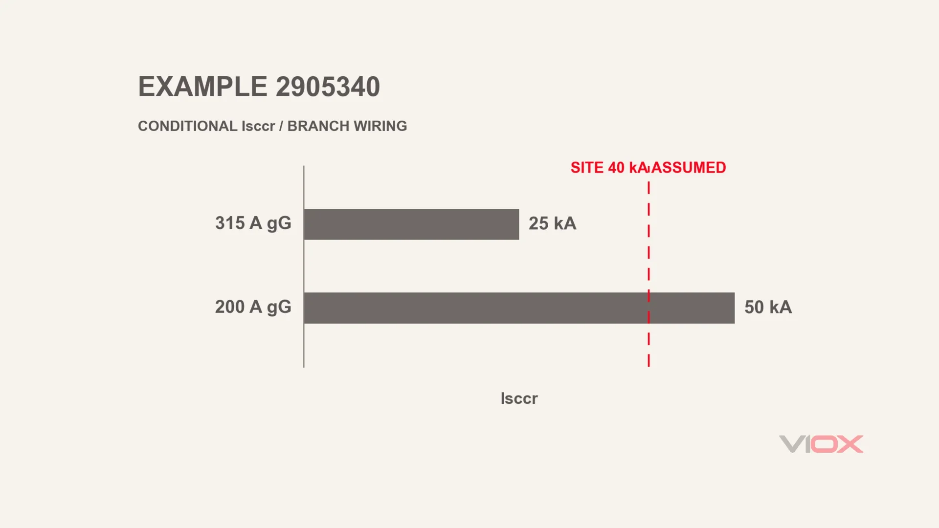
Use Phoenix Contact VAL-SEC-T2-3S-350-FM, item 2905340 as a documentation example, not a recommendation or VIOX equivalent. Its manufacturer data sheet, retrieved for this guide, provides these IEC-side values:
| Published field | Value and condition |
|---|---|
| Maximum backup fuse, branch wiring | 315 A gG |
| Isccr with backup fuse up to 315 A gG | 25 kA |
| Isccr with backup fuse up to 200 A gG | 50 kA |
For this worked check, assume a supported AC system, branch wiring and an engineering study giving 40 kA RMS available fault current at the SPD connection. That fault level is an illustrative project input, not a manufacturer measurement.
Consider a 315 A gG candidate. It meets the published branch-wiring ceiling, but the associated 25 kA condition does not cover the assumed 40 kA location. Reject that candidate for this condition.
Now consider 200 A gG. It is within the branch ceiling and within the data sheet’s 50 kA condition, which covers the assumed fault level. It therefore passes this conditional-rating screen. The selected fuse itself must also have adequate breaking capacity at the application voltage; verify that from its own data, not from the SPD’s Isccr row.
Before release, confirm the manufacturer’s full installation requirements, impulse coordination, conductor protection and actual fuse/holder specification. The result identifies a documented gG candidate, not an automatic instruction to install the maximum allowable fuse. It also gives no equivalent MCB or SCB amperes. Changing to through wiring requires a fresh check of that arrangement’s published limits.
What the VIOX Product Page Establishes
The VIOX VSP1-C40/2(S) page publishes In/Imax, voltage variants, protection levels and a maximum backup-fuse field of 125 A gL/gG. Its short-circuit row lists 25 kA / 50 kA without fully mapping the conditions in that public table. Request the exact variant’s instructions and combination evidence before specifying its backup; do not assume the larger figure applies to every arrangement.
No dedicated VIOX SCB offering was verified in the public catalogue checked for this guide. An SCB proposal therefore remains an industry-level option requiring its own documentation. Broader product choices and cost factors belong in the SPD selection guide and SPD price guide.
FAQ
Does an SPD need backup protection?
It needs a verified fault-disconnection arrangement. That may be integrated, provided by an acceptable upstream device or supplied by a dedicated branch device. The exact SPD instructions determine whether an additional external fuse, breaker or dedicated disconnector is required.
Can I use my existing MCB as SPD backup protection?
Only if the exact SPD and installation documentation support that device, rating and arrangement. Resettable operation alone is not evidence. Use the existing-breaker guide linked above for the reuse decision rather than assuming any upstream MCB qualifies.
Can an SCB replace an ordinary MCB for an SPD?
Only with matching system, fault-current and impulse-duty evidence and acceptance under the applicable installation rules. Check the complete SPD/SCB pairing. Do not treat a dedicated SPD device as a general replacement for load-circuit overcurrent protection.
What size backup fuse does my SPD need?
Start with the exact SPD manufacturer’s maximum backup-fuse rating and class, then apply its conditional short-circuit and impulse requirements. The maximum is a ceiling, not a universal prescription. Use the sizing checks above; do not convert the SPD’s surge kA into fuse amperes.
My SPD indicator still shows green after the backup device tripped — is the SPD still protecting?
Green alone cannot confirm the protection path is available. A mechanical flag may still indicate an intact module although its branch is disconnected. Have qualified personnel verify the backup state, branch continuity, module indication and fault cause under safe isolation procedures before restoring service.
Sources and Review Scope
Technical sources are linked beside their claims. The worked example uses published manufacturer data and an expressly assumed site input; it is not a VIOX test. Manufacturer examples are evidence illustrations, not endorsements. Prepared by the VIOX Team; no independent laboratory test or named engineering sign-off is claimed.