On this page
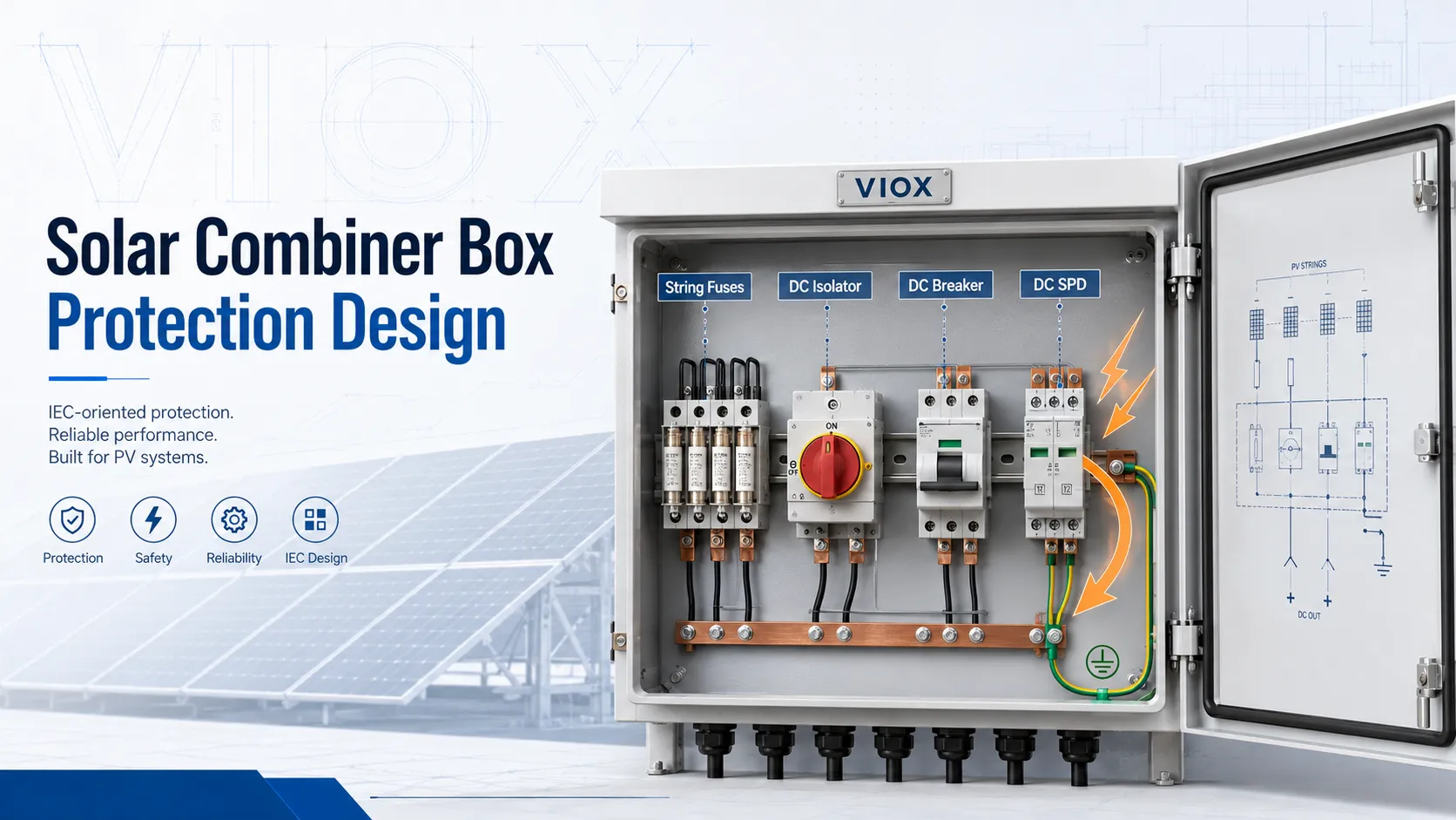
Solar combiner box protection design is not about filling the enclosure with as many protective devices as possible. It is about assigning the correct job to each device and making sure those devices work together under real photovoltaic (PV) operating conditions.
In a well-designed PV combiner box:
- String fuses address reverse-current and string-level fault exposure.
- DC isolators provide safe manual disconnection when selected for PV DC duty.
- DC breakers provide rated overcurrent protection and switching/isolation functions only within their tested application limits.
- Surge protective devices (SPDs) limit transient overvoltage from lightning-related or switching surges.
The most common design error is role confusion. A DC isolator is not a fuse. A fuse is not a service disconnect. An SPD is not an overcurrent device. A DC breaker does not automatically remove the need to evaluate string fusing. Good protection design starts by separating these functions clearly.
If you need broader background first, see what a solar combiner box does or the PV combiner box guide. This article focuses specifically on protection coordination.
Solar Combiner Box Protection Devices Compared
| Device | Main role in the combiner box | What it does not replace | Key selection checks |
|---|---|---|---|
| String fuse | Protects string conductors/modules where reverse current from parallel strings may exceed safe limits | DC isolator, SPD, feeder breaker, enclosure layout design | gPV/PV-rated fuse, voltage rating, current rating, module maximum series fuse rating, holder rating |
| DC isolator | Provides local manual disconnection for maintenance or emergency access | Overcurrent protection, surge protection, string fuse coordination | DC voltage/current rating, utilization category, pole arrangement, isolation suitability, load-break rating if required |
| DC breaker | Provides DC-rated overcurrent protection and may provide switching/isolation if designed for it | Every string fuse decision, SPD, PV-specific disconnector requirements | DC breaking capacity, voltage rating, polarity, pole wiring, trip curve/current rating, standard context |
| SPD | Limits transient overvoltage and diverts surge current through a defined protection path | Overcurrent protection, fault interruption, disconnection, wrong polarity correction | Ucpv/MCOV, Up, In/Imax or Iimp as applicable, Type 1/Type 2, backup protection, lead length, earthing path |
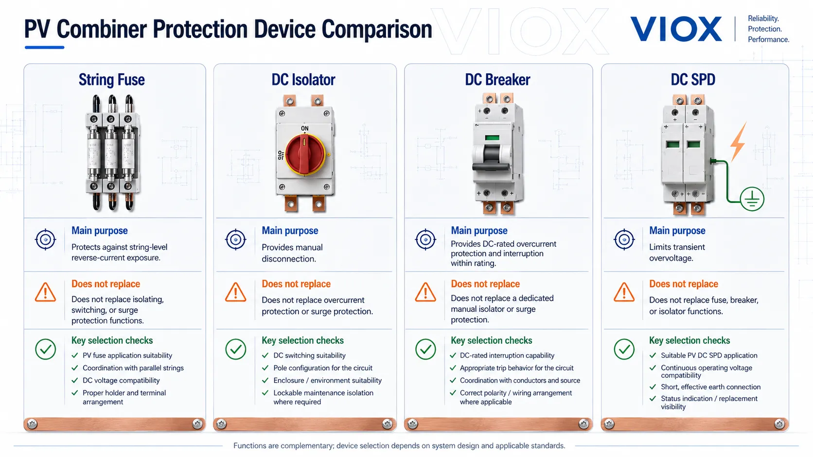
This table is the foundation. If a design treats these four devices as interchangeable, the protection scheme will look complete but behave poorly in a real fault, maintenance, or surge event.
Why Protection Coordination Matters in a PV Combiner Box
A solar combiner box brings multiple PV strings together before feeding an inverter or downstream DC protection stage. That point of convergence creates several risks:
- reverse current from healthy strings into a faulted string
- DC arc interruption difficulty
- overcurrent in the combined output circuit
- transient overvoltage from lightning-induced or switching surges
- heat concentration inside outdoor enclosures
- maintenance access risk if disconnection and labeling are unclear
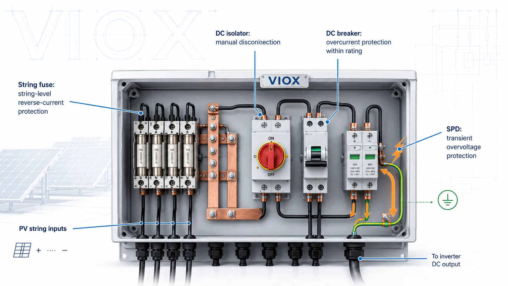
The box is not only a wiring junction. It is a protection boundary. A weak device choice in one part of the box can undermine the rest of the system.
For example, a string fuse may protect one string from reverse-current exposure, but it does not provide a convenient local disconnection point for service. A DC isolator may make maintenance safer, but it will not clear a short circuit like a properly rated protective device. An SPD may protect against transient overvoltage, but it cannot interrupt sustained fault current.
This is why the protection scheme should be designed as a system, not as a collection of catalog parts.
Standards and Ratings to Keep in View
The exact standard framework depends on region, project specification, voltage class, and product certification. In general, designers commonly encounter the following contexts:
| Area | Common standard context | Why it matters |
|---|---|---|
| PV string fuses | IEC 60269-6 / gPV fuse-link concepts, UL/market-specific PV fuse requirements | PV fuses must interrupt DC fault current under PV conditions |
| DC switch-disconnectors / isolators | IEC 60947-3 style switch-disconnector and utilization-category context | DC switching and isolation must be verified for the application |
| DC circuit breakers | IEC 60947-2 or other applicable DC breaker standards/listings | Breaking capacity and DC voltage rating must match system conditions |
| PV DC SPDs | IEC 61643-31 for SPDs connected to the DC side of PV installations | SPD voltage, surge current, and failure behavior differ from ordinary AC SPDs |
| PV array design | IEC 62548 / IEC 60364-7-712 style installation frameworks, plus local code | Overcurrent protection, disconnection, earthing, and cable sizing are installation-dependent |
Do not treat these references as a universal checklist for every country. They are design anchors. Final product selection must follow the target market, project specification, manufacturer datasheets, and local code.
Step 1: Define the PV Combiner Box Duty
Before choosing fuses, isolators, breakers, or SPDs, define what the combiner box is expected to do.
Ask these questions first:
- How many PV strings enter the box?
- What is the maximum system DC voltage?
- Is the box installed near the array, near the inverter, or at another transition point?
- Does the box only combine strings, or must it also provide local isolation?
- Does the inverter already provide input protection or disconnection?
- Is the system floating, grounded, or transformerless?
- What lightning exposure and earthing conditions apply?
- Is the installation 600V, 1000V, 1500V, or another voltage class?
If the voltage class is still being decided, see 600V vs 1000V vs 1500V solar combiner box ratings and the 1000V solar combiner box compliance guide.
Step 2: Coordinate String Fuses
String fuses are mainly about protecting against reverse-current and fault-current exposure at string level. They become especially important when multiple strings are paralleled and a faulted string may receive current contribution from the other strings.
A string fuse decision should not be made by habit. It should be based on:
- the number of parallel strings
- module short-circuit current and temperature-adjusted current expectations
- the module manufacturer’s maximum series fuse rating
- string conductor ampacity
- inverter input design
- local code or project standard
- the fuse holder’s DC voltage and current rating
What string fuses do well
String fuses are strong for selective, string-level protection. If one string has a fault, the fuse can help limit damage to that string and reduce the chance that parallel strings continue feeding the fault.
What string fuses do not do
String fuses do not provide manual isolation for the whole combiner output. They do not replace surge protection. They do not solve poor conductor routing or thermal crowding. They also do not make an AC-rated fuse holder acceptable for PV DC use.
| Fuse design point | Correct approach | Common mistake |
|---|---|---|
| Fuse type | Use PV/DC-rated fuse-links and holders appropriate to the voltage class | Selecting a general AC fuse because the amp rating looks correct |
| Module limit | Check the module maximum series fuse rating | Oversizing fuses beyond module documentation |
| Parallel strings | Evaluate reverse-current contribution | Adding or omitting fuses without checking string architecture |
| Holder design | Match fuse holder voltage, current, heat, and service access | Using a holder that overheats or is hard to service |
For deeper fuse support, see AC fuse vs DC fuse, DC fuse breaking capacity for PV systems, and preventing fuse nuisance tripping in solar combiner boxes.
Step 3: Define the DC Isolator Role
A DC isolator is used to disconnect a PV circuit so that equipment can be serviced more safely. In a combiner box, it may be installed on the combined output side or as part of a broader local disconnection strategy.
The important point is that a DC isolator is primarily a switching and isolation device, not an overcurrent protection device.
What to check for a DC isolator
- rated DC voltage under the maximum PV open-circuit voltage condition
- rated operational current
- load-break capability if it will be opened under load
- pole configuration and series-pole wiring requirement
- polarity limitations, if any
- suitability for PV DC application
- handle locking and clear ON/OFF indication
- enclosure integration and cable entry arrangement
DC switching is not equivalent to AC switching. A device that is acceptable on an AC circuit cannot be assumed safe for DC PV duty. DC arcs do not naturally pass through a current zero point, so the internal contact gap, arc chamber, magnet system, and pole arrangement matter.
For more context, see What Is a DC Isolator Switch?, DC Isolator vs AC Isolator Switch, and How to Read DC Isolator Switch Ratings.
Can a DC Isolator and a DC Breaker Replace Each Other?
Sometimes, but only when the required function is the same. A DC isolator and a DC breaker can both appear at the combiner box output, and both may be used to disconnect a PV circuit if they are correctly rated for PV DC service. But they are not automatically interchangeable.
The practical rule is:
- If the job is manual disconnection / isolation only, a properly rated DC isolator is usually the cleaner choice.
- If the job includes overcurrent protection or fault interruption, a DC breaker or fuse-based protection strategy is required.
- If a DC breaker is used as the main output device, it may replace a separate isolator only if the breaker is also rated and accepted for the required isolation/switching duty.
- If string fuses and upstream/downstream protective devices already handle overcurrent protection, the combiner output may only need a DC isolator for service disconnection.
| Scenario | Better first choice | Why |
|---|---|---|
| Combiner box needs only local manual disconnection before inverter service | DC isolator | Simpler device for switching/isolation when overcurrent protection is handled elsewhere |
| Output cable from combiner box needs overcurrent protection | DC breaker or fuse-based protection | Isolator alone will not clear overcurrent or short-circuit faults |
| Project wants one output device for switching, isolation, and overcurrent protection | DC breaker, if rated for all required functions | Must verify DC breaking capacity, isolation marking/function, voltage, poles, and application suitability |
| Multiple parallel strings already have string fuses and inverter input protection is specified | DC isolator may be enough at combiner output | Depends on local code, inverter design, feeder protection, and project specification |
| High-voltage PV string/array circuit where switching under load is required | PV-rated DC isolator or DC breaker with load-break capability | Must verify utilization category or manufacturer PV DC rating |
| Maintenance lockout point required at the array or combiner | Lockable DC isolator or breaker suitable for isolation | The key requirement is a clearly rated, lockable isolation function |
So yes, the products may replace each other in some layouts, but only after the designer identifies the exact role: isolation, load switching, overcurrent protection, or a combination of these. In a PV combiner box, the best choice is not based on product name; it is based on which protective function is missing from the overall system.
Step 4: Select DC Breakers Carefully
DC breakers are often used at the combined output of a combiner box, or in downstream DC protection stages. They may provide overcurrent protection, switching, and sometimes isolation, but only when the device is rated and applied correctly.
The breaker should be checked for:
- rated DC voltage
- rated current
- interrupting capacity under DC conditions
- pole configuration and series connection requirements
- polarity marking or non-polarized design
- trip behavior and suitability for PV circuit behavior
- coordination with upstream fuses and downstream inverter protection
- installation temperature and enclosure derating
Breaker vs isolator: do not blur the function
A DC breaker and a DC isolator can look similar from outside the enclosure, especially when both use a rotary handle or DIN-rail format. Their design job is different.
| Device | Main role | Key risk if misused |
|---|---|---|
| DC isolator | Manual disconnection and isolation | It may not clear overcurrent or short-circuit faults |
| DC breaker | Overcurrent protection and interruption within rating | It may not be suitable as the required local disconnector unless marked/rated for that role |
| DC fuse | Fast string-level or conductor protection | It is not a convenient switching device for routine operation |
For adjacent detail, see What Is a DC Circuit Breaker?, How to Choose a DC Circuit Breaker, DC Circuit Breaker vs Fuse, and DC Isolator vs DC Circuit Breaker.
Step 5: Select and Place the SPD
SPDs protect against transient overvoltage. In PV systems, surges may come from lightning-induced effects, nearby switching events, long cable runs, or earthing-system interactions. A combiner box SPD is not a decorative accessory; it must be selected around the actual DC system.
Key checks include:
- Ucpv or maximum continuous operating voltage suitable for PV DC voltage
- voltage protection level (Up)
- nominal and maximum discharge current ratings as applicable
- Type 1, Type 2, or Type 1+2 requirement based on protection concept
- backup protection requirement
- failure indication and remote signaling, if needed
- connection mode and earthing arrangement
- short, controlled lead routing
SPD placement matters
An SPD with good ratings can perform poorly if it is installed with long, looping conductors. Surge current flowing through long leads creates additional voltage drop. In practical terms, the effective protection at the inverter or DC equipment can be worse than the printed SPD Up value suggests.
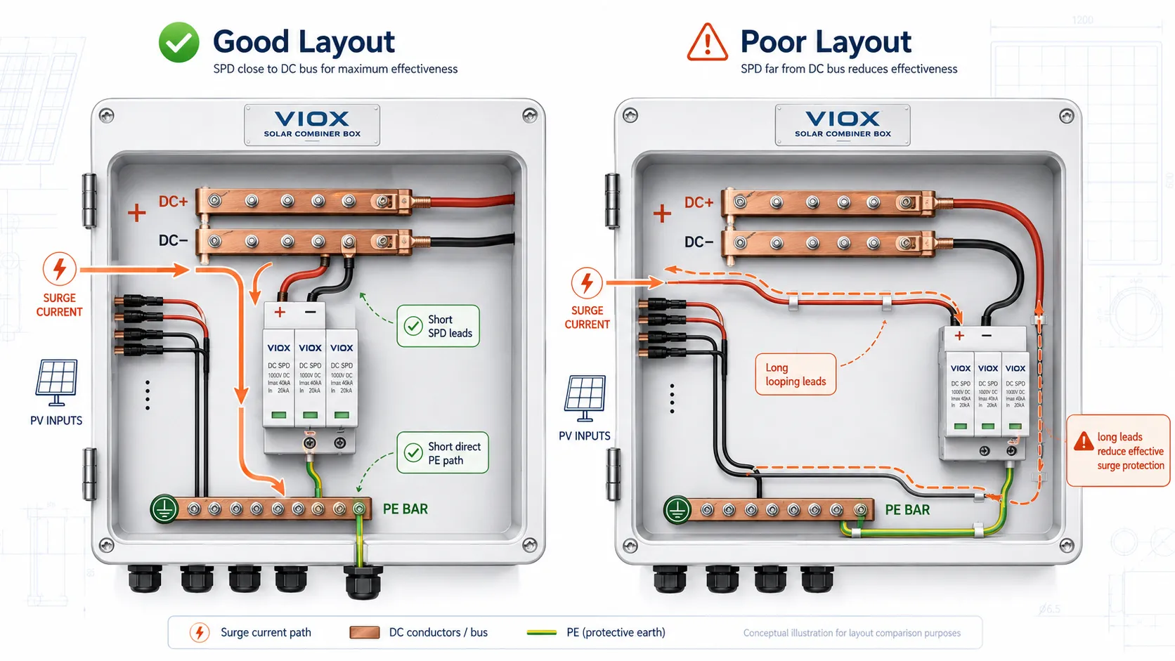
Place the SPD so its connection path is short, direct, and consistent with the manufacturer’s wiring diagram and the project’s earthing concept.
For deeper SPD selection, see How to Choose the Right SPD for Your Solar Power System, Type 1 vs Type 2 vs Type 3 SPD, Uc and Up on SPD, Where to Install SPDs, and SPD Installation Mistakes.
A Practical Protection Coordination Workflow
The safest approach is to sequence the decisions.
| Step | Design action | Why it matters |
|---|---|---|
| 1 | Define system voltage, string count, and inverter input arrangement | Sets the entire protection boundary |
| 2 | Evaluate string-level reverse-current exposure | Determines fuse need and fuse role |
| 3 | Select PV-rated string fuse and holder if required | Prevents incorrect AC/general fuse assumptions |
| 4 | Define whether local isolation is required | Determines DC isolator need and placement |
| 5 | Select output breaker or protective device if required | Coordinates feeder protection and switching function |
| 6 | Select SPD based on voltage, exposure, and earthing | Prevents generic SPD selection |
| 7 | Review layout, heat, cable routing, and service access | Prevents field failures that are not visible in a schematic |
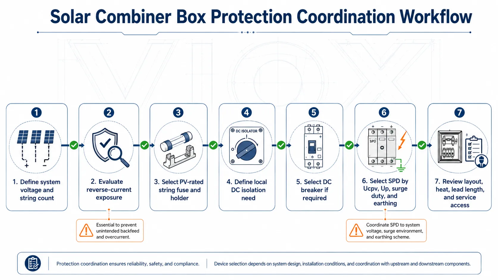
This workflow keeps the design from drifting into the common pattern of “one device solves everything.” It also makes the bill of materials easier to defend during project review.
Typical Protection Patterns
| PV combiner pattern | Fuse role | DC isolator role | DC breaker role | SPD role |
|---|---|---|---|---|
| Small array with few parallel strings | May depend strongly on module limits and local code | Often used for service disconnection | May be downstream or integrated elsewhere | Evaluated based on exposure and inverter sensitivity |
| Commercial rooftop combiner | Often important due to multiple parallel strings | Commonly used for local isolation | Often used at combined output or downstream DC protection stage | Usually important because rooftop arrays are surge-exposed |
| Utility-scale or high-voltage DC array | Must be checked carefully against system voltage and holder rating | Requires robust PV DC switching/isolation design | Must match high DC voltage and interrupting requirements | Often part of a coordinated site-wide surge protection concept |
| Inverter-integrated input protection | May be reduced or changed depending on inverter design | May still be required locally by project design | May be integrated, external, or both | Should still be coordinated with DC cable routing and earthing |
Layout and Thermal Design Are Part of Protection
Protection coordination is not only electrical. A combiner box can use correct components and still fail because of layout.
Pay attention to:
- fuse holder heat dissipation
- spacing between heat-generating devices
- cable bending radius and conductor routing
- SPD lead length and grounding path
- separation between DC positive and negative conductors where required
- service access to fuses, isolators, breakers, and SPD modules
- water ingress risk from poor cable gland arrangement
- label visibility for maintenance teams
If the enclosure design is still open, review PV combiner box enclosure selection, combiner box placement indoor vs outdoor, solar combiner box overheating causes and solutions, and the solar combiner box inspection checklist.
Common Design Mistakes
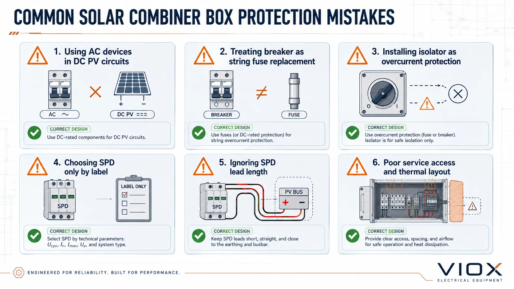
Mistake 1: Treating the breaker as a universal replacement for fuses
A DC breaker at the combined output may be essential, but it does not automatically solve string-level reverse-current protection. String fuse need must still be evaluated.
Mistake 2: Using AC protective devices in DC PV circuits
PV DC interruption is different from AC interruption. Devices must be rated for the actual DC voltage and application.
Mistake 3: Installing an isolator and assuming overcurrent protection is solved
A DC isolator gives a disconnection function. It does not automatically provide short-circuit or overload protection.
Mistake 4: Choosing SPD only by “PV SPD” label
The SPD must match Ucpv/MCOV, surge duty, installation point, backup protection, and earthing arrangement. The label alone is not enough.
Mistake 5: Ignoring lead length and layout
Long SPD leads, crowded fuse holders, and poor conductor routing can weaken a technically correct component choice.
Mistake 6: Designing for the schematic but not the technician
The final box must be inspectable and serviceable. Fuse replacement, isolator operation, breaker reset, SPD status checking, and label reading must be realistic in the installed environment.
Designer Checklist
| Checkpoint | Confirm before release |
|---|---|
| String architecture | Number of parallel strings and fault contribution are known |
| Module protection limit | Module maximum series fuse rating is checked |
| Fuse design | Fuse-link and holder are PV DC rated and properly located |
| Isolator design | DC isolator rating, pole arrangement, and load-break/isolation function are confirmed |
| Breaker design | DC breaker rating, breaking capacity, polarity, and role are defined |
| SPD design | Ucpv, Up, discharge current, Type, backup protection, and earthing path are checked |
| Layout | Thermal spacing, conductor routing, SPD lead length, and maintenance access are reviewed |
| Documentation | Schematic, BOM, labels, warning signs, and inspection points match the actual box |
FAQ
Can a DC breaker replace string fuses in a solar combiner box?
Not automatically. A DC breaker at the combined output may protect and isolate the outgoing circuit, but string fuses address string-level reverse-current exposure from parallel strings. These are different protection questions.
Is a DC isolator the same as a DC breaker?
No. A DC isolator provides manual disconnection and isolation when rated for the application. A DC breaker provides overcurrent protection and interruption within its rating. Some products may combine functions, but the datasheet must explicitly support the intended use.
Does every solar combiner box need string fuses?
Not always. The need depends on string count, module maximum series fuse rating, reverse-current exposure, inverter input design, and local requirements. The decision should be calculated or justified, not copied from a generic design.
Does every solar combiner box need an SPD?
Many PV combiner boxes include SPD protection because PV arrays are exposed to surge risk, but final selection depends on site exposure, system voltage, earthing arrangement, inverter sensitivity, and project requirements.
Where should the SPD be installed inside the combiner box?
The SPD should be installed close to the conductors and protection zone it is intended to protect, with short and direct leads to the appropriate protection path. Always follow the SPD manufacturer’s wiring diagram and the project earthing design.
Can AC breakers or AC isolators be used in a DC combiner box?
They should not be assumed suitable. DC switching and interruption are more demanding because the current does not naturally cross zero. Use devices explicitly rated for PV DC service at the required voltage and current.
What is the most common protection coordination mistake?
The most common mistake is assigning the wrong job to the wrong device: relying on a breaker for string-fuse coordination, treating an isolator as overcurrent protection, or installing an SPD without checking voltage and lead layout.
Summary
Solar combiner box protection design is a coordination problem. Fuses, DC isolators, DC breakers, and SPDs each solve a different part of the risk profile.
Use string fuses to manage string-level reverse-current and fault exposure. Use DC isolators for local disconnection and isolation. Use DC breakers where DC-rated overcurrent protection and interruption are required. Use SPDs to reduce transient overvoltage stress.
The best design is not the one with the most components. It is the one where every component has a clear role, correct rating, proper location, and documented coordination with the rest of the PV system.