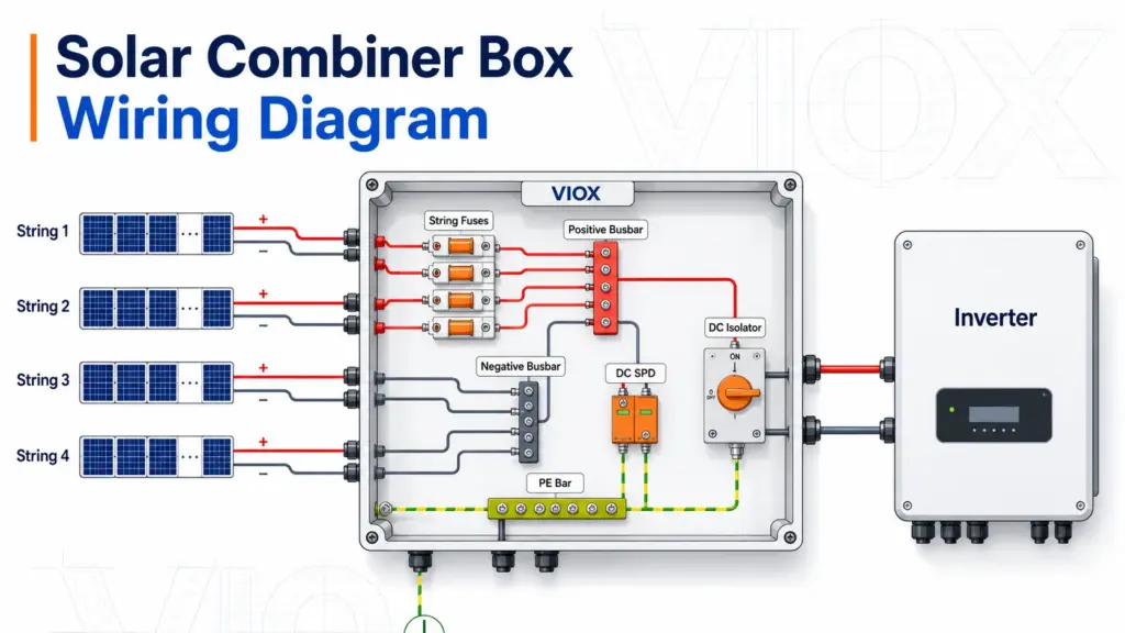
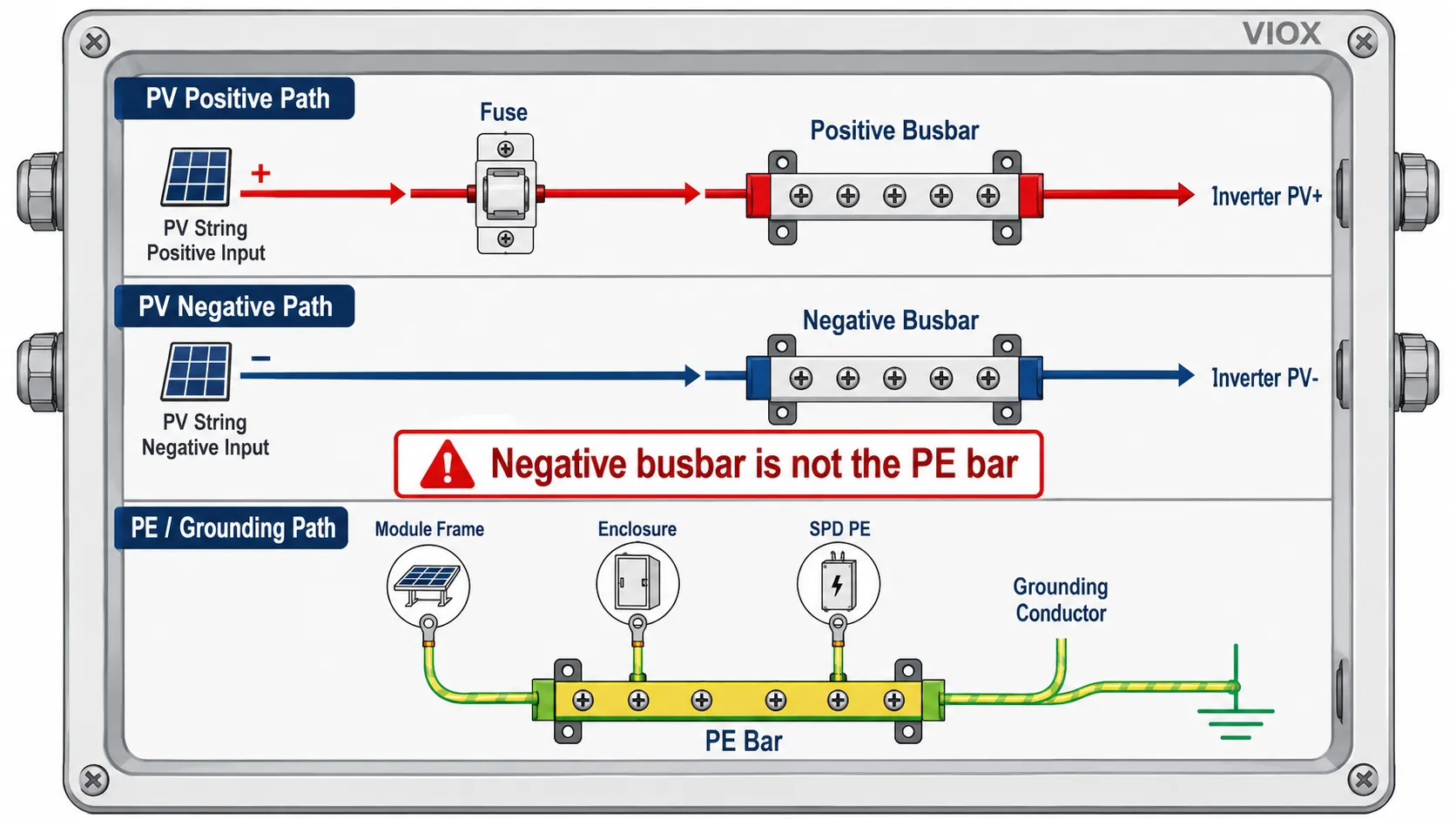
A solar combiner box wiring diagram shows how multiple photovoltaic (PV) strings are connected into one or more DC output circuits before going to the inverter. The normal wiring path is:
PV string positive → string fuse or DC breaker → positive busbar → DC isolator or output breaker → inverter DC positive input
PV string negative → negative terminal or negative busbar → inverter DC negative input
PV module frames / equipment grounding conductor → PE or grounding bar → site grounding system
DC surge protective device (SPD) → connected across the DC conductors and protective earth according to the SPD connection mode
That simple path is the core of almost every PV combiner box diagram. The details change depending on the number of strings, inverter maximum power point tracking (MPPT) inputs, whether each string needs a fuse, whether the output uses a DC isolator or DC breaker, and how the SPD is wired.
This guide focuses on DC PV combiner box wiring, not AC combiner panels. If you need the broader product overview, see the VIOX PV combiner box guide. If your main question is device coordination, see Solar Combiner Box Protection Design.
Key Takeaways
- A combiner box does not put panels in series. The series connection is normally made in the field to form each PV string.
- Inside the combiner box, strings are usually combined in parallel, so voltage stays roughly the same while current adds.
- The positive conductor of each string normally passes through a string fuse or DC breaker before reaching the positive busbar.
- The negative conductors usually land on a negative terminal block or busbar, unless the design uses both positive and negative fusing.
- The protective earth (PE) or equipment grounding conductor is separate from the DC negative conductor in most modern transformerless PV systems.
- A DC SPD must have a short, direct connection to the grounding bar; long SPD leads increase let-through voltage during a surge.
- Multi-MPPT inverters often require separate combiner outputs. Do not combine strings from different MPPT groups unless the inverter design allows it.
Solar Combiner Box Wiring Diagram at a Glance
| Wiring point | Typical connection | What to verify |
|---|---|---|
| PV string positive | String input + to fuse holder or DC breaker |
Polarity, string Isc, fuse rating, terminal torque |
| PV string negative | String input - to negative terminal or busbar |
Polarity, terminal grouping, insulation from PE |
| Positive output | Positive busbar through DC isolator/breaker to inverter PV+ |
Combined current, conductor size, DC voltage rating |
| Negative output | Negative busbar to inverter PV- |
Current rating, terminal capacity, cable routing |
| PE / grounding | Module frames, enclosure, SPD earth lead to PE bar | Continuity, bonding, local grounding rules |
| SPD | +, -, and PE terminals according to SPD wiring mode |
Ucpv rating, Type 1/2 need, shortest practical earth lead |
| Monitoring CT/shunt | Around each string or output conductor if fitted | Direction, polarity, communication wiring |
Before Reading the Diagram: Know What the Combiner Box Actually Combines
A PV combiner box combines parallel string circuits, not individual module wiring.
For example:
- Ten modules in series form one string.
- Four identical strings enter the combiner box.
- The combiner box combines those four string outputs into one output circuit, or into two grouped outputs for a two-MPPT inverter.
This distinction matters because many wiring mistakes happen when installers treat the combiner box as if it creates the series string. It normally does not. The string voltage is already created before the cable reaches the combiner box.
Basic 4-String DC Combiner Box Wiring Diagram
The most common diagram is a 4-string input combiner with one positive busbar, one negative busbar, string fuses on the positive side, a DC SPD, and one output to the inverter.
PV String 1 +  ── Fuse 1 ┐
PV String 2 +  ── Fuse 2 ├── Positive Busbar ── DC Isolator / DC Breaker ── Inverter PV+
PV String 3 +  ── Fuse 3 ┤
PV String 4 +  ── Fuse 4 ┘

PV String 1 -  ──────────┐
PV String 2 -  ──────────├── Negative Busbar ─────────────────────────────── Inverter PV-
PV String 3 -  ──────────┤
PV String 4 -  ──────────┘

PV frames / enclosure ───── PE Bar ───────────────────────────────────────── Site grounding

DC SPD:
SPD + terminal  ─────────── Positive Busbar or line side connection
SPD - terminal  ─────────── Negative Busbar or line side connection
SPD PE terminal ─────────── PE Bar, with the shortest practical conductor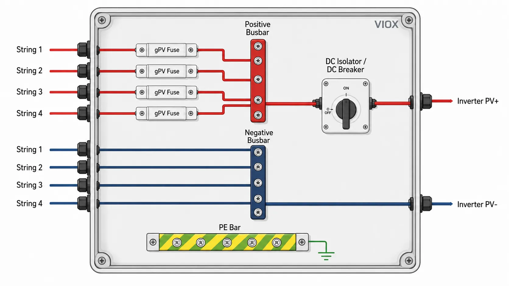
This diagram is correct only when all four strings are suitable to be paralleled together. That usually means the strings have the same module type, same number of modules in series, similar orientation, and the inverter MPPT input is intended to receive the combined current.
Single-MPPT vs Multi-MPPT Wiring
The inverter MPPT arrangement is one of the most important wiring decisions.
Single-MPPT combiner wiring
If the inverter has one MPPT input and the strings are electrically matched, the combiner output may be one positive and one negative pair.
4 matched PV strings → one fused combiner group → one PV+ / PV- output → inverter MPPT 1This is common when all strings face the same direction and have similar irradiance conditions.
Two-MPPT combiner wiring
If the inverter has two independent MPPT inputs, the combiner box should normally keep those MPPT groups separate.
String 1 + String 2 → Combiner Output A → Inverter MPPT 1
String 3 + String 4 → Combiner Output B → Inverter MPPT 2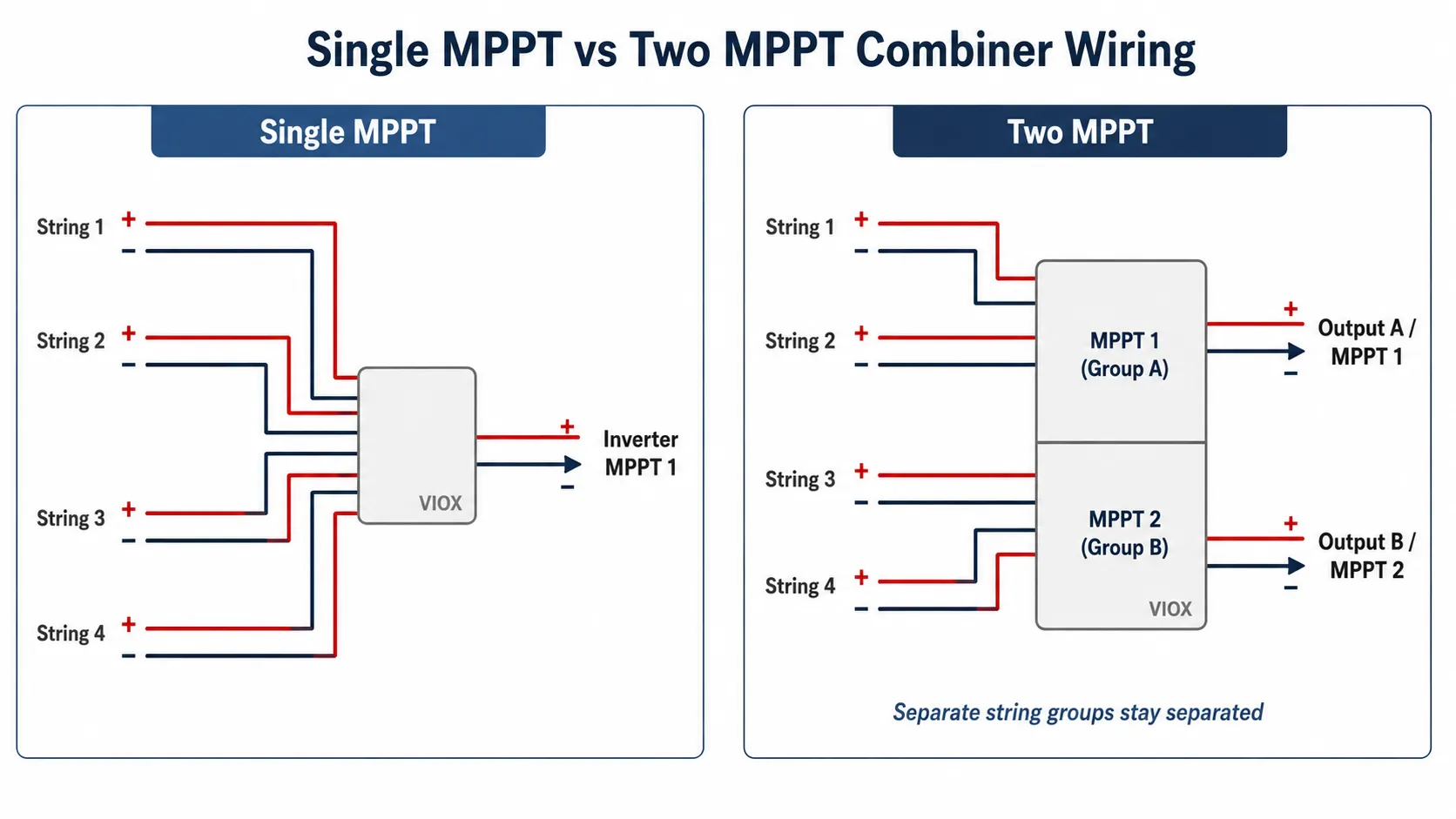
Do not combine all strings into one busbar and then split the output to two MPPT inputs unless the inverter manufacturer explicitly allows that arrangement. Separate MPPT inputs are designed to track different voltage-current points. Combining mismatched strings before the inverter can reduce energy yield and complicate fault diagnosis.
Where the String Fuses Go
In a typical fused DC combiner box, each string positive conductor lands on an individual gPV fuse holder before the positive side is combined.
String + input → gPV fuse → positive busbarThe purpose of the string fuse is not to protect the module from producing too much current. A PV module is current-limited by nature. The fuse is mainly used to protect a faulted string and its conductors from reverse current supplied by other parallel strings.
For this reason, string fusing becomes more important as the number of parallel strings increases. Whether fusing is required depends on the module maximum series fuse rating, the number of parallel strings, conductor ampacity, local code, and inverter/combiner design.
For international projects, PV fuse links are commonly specified as gPV fuses under IEC 60269-6 terminology. In North American projects, PV source circuit protection must be checked against the applicable NEC Article 690 requirements and product listings.
Should Both Positive and Negative Be Fused?
Many diagrams show only the positive side fused. Other systems use both positive and negative fusing. The correct choice depends on the grounding arrangement, inverter topology, local code, and equipment instructions.
| System condition | Common wiring approach | Important caution |
|---|---|---|
| Floating or ungrounded PV array | Positive-side fusing or two-pole protection may be used depending on design | Do not assume DC negative is bonded to ground |
| Functionally grounded system | Fuse placement depends on grounding method and code | Follow inverter and code requirements |
| Bipolar PV array | Positive and negative sub-arrays may require special protection | Do not use a standard simple combiner diagram |
| Utility-scale or monitored combiner | Both-pole switching/protection may be project-specific | Follow engineered drawings |
For that reason, a safe wiring diagram should not assume positive-only fusing for every PV system. The better engineering rule is: follow the listed combiner box design, inverter manual, local code, and the PV module maximum series fuse rating.
DC Isolator or DC Breaker Wiring at the Output
Many combiner boxes include a DC isolator, DC switch-disconnector, or DC breaker at the combined output.
The output device is normally placed after the strings have been combined:
String fuses → positive busbar → output DC isolator/breaker → inverter PV+
Negative busbar ───────────────────────────────────────────→ inverter PV-
In some designs, both positive and negative output conductors pass through a two-pole or four-pole DC switch-disconnector. This is common when the device is used as a local array disconnect.
Do not assume a DC isolator and a DC breaker are interchangeable. A DC isolator is primarily for manual disconnection and isolation. A DC breaker can provide overcurrent protection only if it is rated for the PV DC voltage, current, interrupting capacity, polarity, and pole wiring arrangement. For a deeper explanation, see DC Isolator vs DC Circuit Breaker.
DC SPD Wiring in a Solar Combiner Box
A DC surge protective device (SPD) is connected in parallel with the PV circuit, not in series with the load current.
Typical SPD connections are:
SPD +  → PV positive bus or line terminal
SPD -  → PV negative bus or line terminal
SPD PE → PE / grounding bar
Depending on the SPD design and earthing system, the internal protection mode may be:
+ to PE- to PE+ to -- a Y-connection or other manufacturer-defined PV SPD arrangement
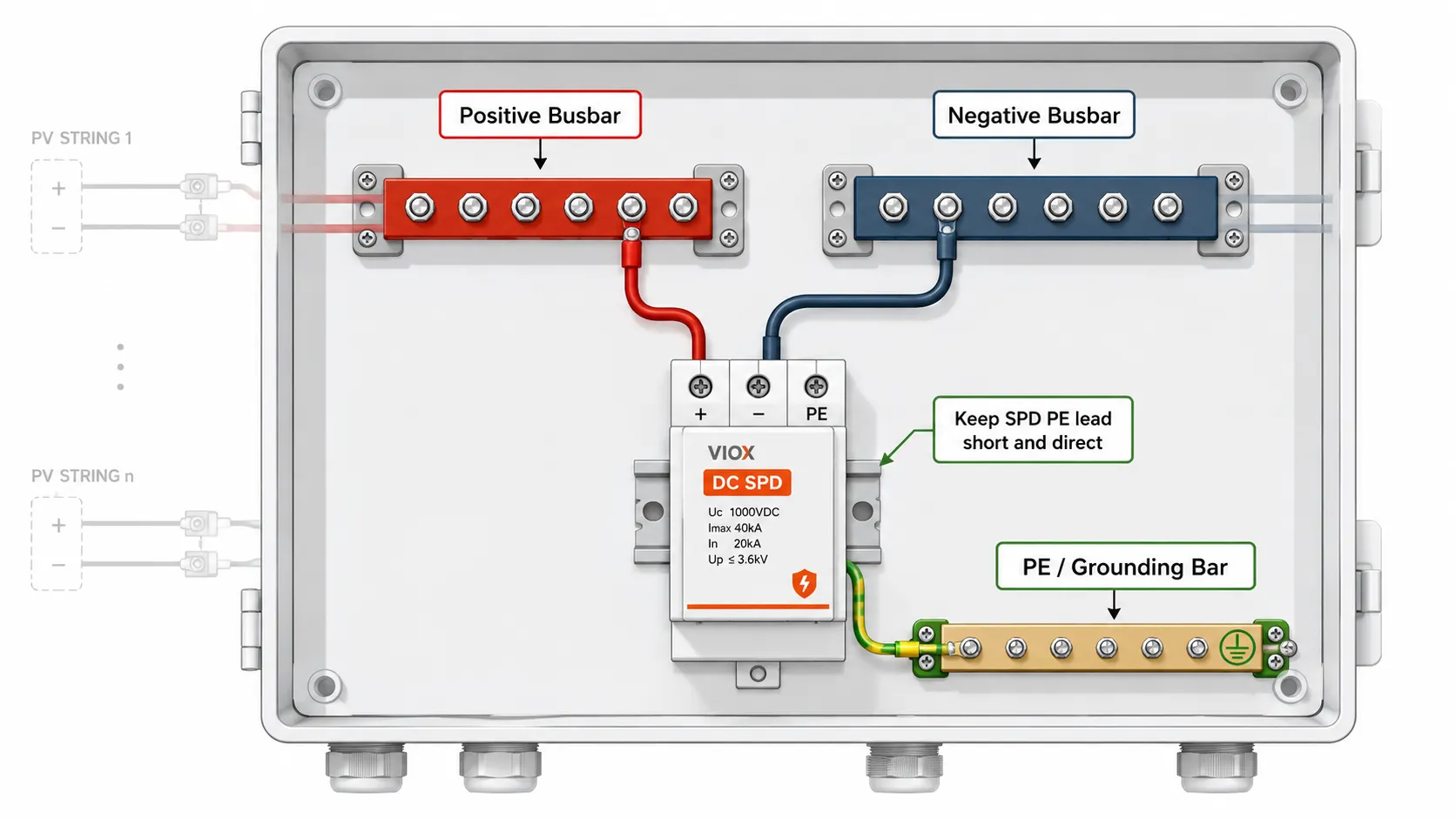
The important wiring principle is that the SPD conductors should be as short and direct as practical. During a surge, every extra length of conductor adds inductive voltage drop, so a neat-looking but long SPD loop can reduce real protection performance.
For DC SPD selection details, see DC Surge Protection Devices and How to Read an SPD Datasheet.
Grounding and PE Bar Wiring
The grounding bar in a solar combiner box is not the same as the negative busbar.
The PE bar normally receives:
- equipment grounding conductors from PV module frames and mounting structures
- the combiner box enclosure bonding conductor
- SPD earth conductor
- outgoing equipment grounding conductor to the grounding system
The negative busbar carries DC return current. The PE bar should not carry normal operating current in a correctly designed system.
Do not bond PV negative to the combiner enclosure unless the inverter/system design specifically requires it. Most modern transformerless PV systems use insulation monitoring or residual current monitoring concepts and require the DC conductors to remain isolated from equipment grounding under normal conditions.
Step-by-Step Solar Combiner Box Wiring Procedure
This sequence is written for a typical DC PV combiner box. Always follow the supplied wiring diagram, inverter manual, and local electrical code.
1. Confirm the design before touching the wires
Before wiring, confirm:
- number of strings
- modules per string
- maximum cold-corrected string open-circuit voltage
- module short-circuit current
- module maximum series fuse rating
- inverter MPPT input voltage and current limits
- combiner box voltage, current, and enclosure ratings
- whether the system is grounded, ungrounded, or functionally grounded
2. Mount the combiner box in the correct location
The combiner box should be accessible for inspection and service while respecting environmental exposure, cable routing, heat, and local clearance rules. Outdoor installations normally require a suitable IP/NEMA enclosure rating, UV-resistant cable entries, and reliable sealing around glands or conduit fittings.
Avoid placing the box where water can sit around cable entries or where direct thermal stress will push internal components beyond their derating limits.
3. Bring PV string cables into the correct entries
Route each PV string pair into the box through the assigned glands or conduit entries. Keep positive and negative conductors identifiable from entry to termination.
Good practice:
- label every string at the cable entry
- keep bending radius within cable manufacturer limits
- avoid crossing conductors over fuse clips or SPD terminals
- leave enough service loop for maintenance, but avoid messy loops near SPD earth wiring
4. Connect string positives to fuses or DC breakers
Each string positive should land on its designated fuse holder or breaker input terminal. The fuse output then connects to the positive busbar.
Do not parallel multiple string positives under one terminal unless the terminal is explicitly rated for multiple conductors.
5. Connect string negatives to the negative terminal block or busbar
Connect each string negative to its assigned negative terminal. In monitored combiner boxes, each negative or positive may pass through a current sensor or monitoring board. Follow the direction marking on the monitoring device.
6. Wire the output conductors to the inverter
The combined positive output goes through the specified output device if fitted. The combined negative output leaves from the negative busbar or output terminal.
Check:
- output conductor ampacity
- inverter input current limit
- terminal temperature rating
- polarity at both ends
- correct MPPT grouping
7. Connect the SPD
Wire the DC SPD according to its label and datasheet. Keep SPD conductors short and direct, especially the PE conductor. If the SPD has remote signaling contacts, route those low-voltage signal wires separately from high-current DC conductors where practical.
8. Connect PE / grounding conductors
Bond the combiner enclosure and all required equipment grounding conductors to the PE bar. Verify grounding continuity after termination.
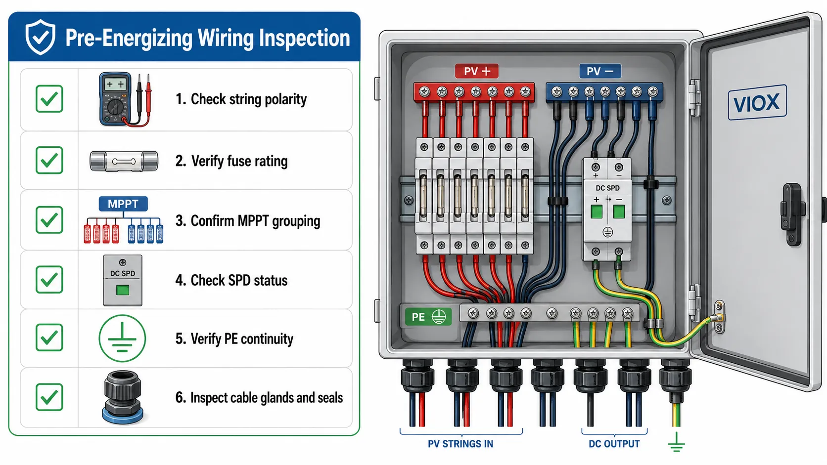
9. Label, inspect, and test before energizing
Before closing the cover:
- check every string polarity
- verify fuse ratings against the design
- confirm no loose wire strands are exposed
- verify terminal torque using the manufacturer value
- check insulation resistance if required by the project
- confirm SPD status indicator is normal
- confirm the DC isolator/breaker is OFF before final connection
- record string Voc values and compare similar strings
Common Wiring Configurations
2-string combiner box
A 2-string combiner may not always need string fuses if the inverter and module design allow direct parallel connection. But many pre-wired boxes still include fuses for maintenance and standardization.
String 1 + → Fuse 1 → Positive bus
String 2 + → Fuse 2 → Positive bus
String 1 - → Negative bus
String 2 - → Negative bus
4-string combiner box
This is the most common educational wiring diagram. It is useful because it shows how parallel string current adds at the busbar.
4 string positives → 4 fuse holders → one positive bus → one output
4 string negatives → one negative bus → one output
4-string, 2-MPPT combiner box
This wiring keeps two groups separate.
String 1 + String 2 → Output A → MPPT 1
String 3 + String 4 → Output B → MPPT 2
The box may look similar from outside, but internally it should have separated positive grouping and separated outputs.
Combiner box with monitoring
In monitored boxes, each string conductor passes through a measurement channel. The monitoring circuit may measure string current, fuse status, SPD status, or temperature.
The key wiring rule is simple: do not bypass the monitoring path when replacing a fuse holder, terminal, or cable.
Wiring Mistakes That Cause the Most Problems
| Mistake | Why it is dangerous | Better practice |
|---|---|---|
| Reversing string polarity | Can damage inverter input or SPD and create fault conditions | Verify polarity with a meter before connecting |
| Combining different MPPT groups | Reduces tracking performance and complicates faults | Keep MPPT groups electrically separate |
| Using AC breakers or isolators on DC PV | DC arcs are harder to interrupt than AC arcs | Use PV-rated DC devices only |
| Long SPD ground lead | Raises real let-through voltage during a surge | Keep SPD PE path short and direct |
| Treating PE bar as negative busbar | Can put operating current on grounding paths | Keep DC negative and PE separate unless design requires bonding |
| Multiple conductors under one terminal | Causes loose connections and overheating | Use terminals listed for the conductor count and size |
| Oversized fuses | May fail to protect conductors or string wiring | Size according to module and code requirements |
| No string labeling | Makes commissioning and troubleshooting slow | Label every string, fuse, and output |
How to Check a Solar Combiner Box Wiring Diagram Before Installation
Use this quick review before approving a diagram:
- Does each PV string have a clearly marked
+and-input? - Does each fused string show the fuse on the correct conductor for the system design?
- Are the positive and negative buses clearly separated from the PE bar?
- Is the SPD connected to
+,-, and PE according to the SPD datasheet? - Is the SPD earth path short and direct?
- Does the output device show whether it is a DC isolator, DC breaker, or switch-disconnector?
- Are multiple MPPT groups separated?
- Are all DC devices rated for the maximum PV voltage?
- Are output conductors sized for combined current and installation conditions?
- Are labels, polarity marks, and warning labels shown?
When You Do Not Need a Separate Combiner Box
Not every PV system needs an external combiner box.
You may not need one when:
- the inverter already has enough independent string inputs
- the inverter includes required string protection and DC switching
- only one string is used
- two strings are connected directly through listed connectors or inverter inputs allowed by the manufacturer
- the project design does not require external monitoring, SPD, or field isolation at the array
However, in commercial, industrial, and utility-scale systems, combiner boxes remain useful because they centralize string protection, DC surge protection, isolation, monitoring, and maintenance access.
FAQ
What is the correct solar combiner box wiring diagram?
The typical DC wiring path is PV string positive to fuse or DC breaker, then to the positive busbar, then through the output isolator or breaker to the inverter. PV string negatives go to a negative busbar or terminal block, while equipment grounding conductors and SPD earth connections go to the PE bar.
Does a solar combiner box connect panels in series or parallel?
A combiner box normally combines already-formed PV strings in parallel. The series connection of modules is usually made outside the combiner box to create each string.
Where should the fuse be placed in a PV combiner box?
In many designs, each string positive conductor passes through an individual gPV fuse before connecting to the positive busbar. Some systems may require different fuse placement or two-pole protection, depending on the grounding method, code, and equipment instructions.
Can I connect all strings to one MPPT input?
Only if the inverter MPPT input is rated for the combined current and the strings are suitable to operate together. If strings face different directions or belong to different MPPT channels, they should usually remain separated.
Is the negative busbar the same as ground?
No. The negative busbar carries DC return current. The PE or grounding bar bonds equipment frames, enclosure parts, and SPD earth conductors. Do not bond negative to ground unless the system design specifically requires it.
Where does the SPD connect in a combiner box?
A DC SPD is connected in parallel with the DC circuit. Its +, -, and PE terminals should follow the SPD wiring diagram. The PE conductor should be as short and direct as practical.
Can an AC breaker be used in a solar combiner box?
Do not assume an AC breaker is suitable for PV DC circuits. DC arcs do not self-extinguish at a current zero crossing like AC arcs. Use devices with explicit PV DC voltage, current, interrupting, polarity, and pole-connection ratings.
What should be tested after wiring a combiner box?
At minimum, installers usually verify polarity, string open-circuit voltage, grounding continuity, terminal tightness, fuse rating, SPD status, enclosure sealing, and output polarity before energizing. Project specifications may also require insulation resistance testing and commissioning records.
Summary
A good solar combiner box wiring diagram is not just a picture of wires. It is a map of protection functions.
The positive string conductors must be routed through the correct string protection. The negative conductors must return through the correct terminal path. The SPD must be wired with a short, direct PE connection. The output device must match the required role, whether isolation, switching, overcurrent protection, or a combination of these. Multi-MPPT designs must keep string groups separate.
If the diagram makes those paths clear, the combiner box becomes easier to install, inspect, troubleshoot, and maintain. If the diagram hides those paths, the installation may still look neat while carrying serious electrical risk.
Sources and Reference Points Used
- Existing VIOX page reviewed: Solar Combiner Box Wiring Diagram
- VIOX internal cluster reference: PV Combiner Box Guide
- VIOX internal cluster reference: Solar Combiner Box Protection Design
- NEC context page: NFPA 70 National Electrical Code
- Standard context for PV fuses: IEC 60269-6 is the IEC low-voltage fuse part for solar photovoltaic energy systems; exact project compliance should be verified against the latest purchased standard text and local code.
