On this page
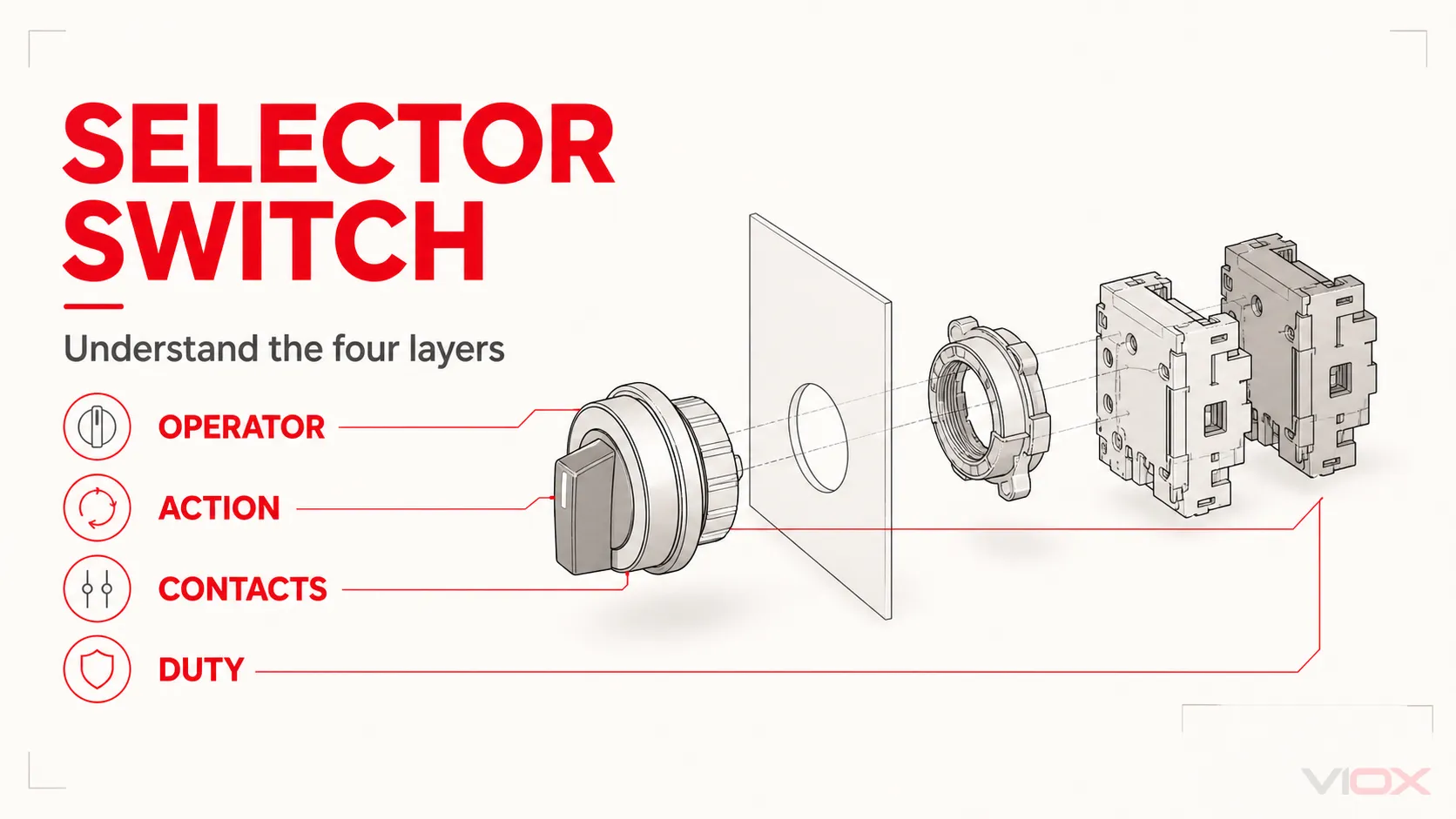
A selector switch is a manually operated control device that lets an operator choose between defined circuit states or machine modes. The front operator may rotate, move as a toggle, or require a key. Its action may be maintained or spring return. The contacts behind the panel determine which circuits are open or closed in each position.
These descriptions answer different questions:
- Rotary or toggle: How does the operator move?
- Selector: What function does the device perform?
- Maintained or spring return: What happens after the operator releases it?
- Contact block or cam program: How does each position change the circuit?
- Control or load duty: What electrical task are the contacts rated to perform?
This is why “rotary switch vs selector switch” is usually the wrong starting comparison: many selector switches are rotary switches. The useful task is to identify the required operator, action, contact logic and circuit duty.
The Four-Layer Selector Switch Map
| Layer | Question | Common options | Specification output |
|---|---|---|---|
| Operator | How should the user make the selection? | Rotary knob, long handle, toggle lever, key operator | Operator style, access and panel interface |
| Positions and action | How many states, and does the operator stay there? | Two or three positions, multi-position, maintained, spring return, mixed action | Position labels and return behavior |
| Contact logic | Which circuits change in each position? | Normally open, normally closed, changeover, multiple contact blocks or a cam program | Position-to-contact table |
| Electrical duty | What does the switch control? | PLC input, relay or contactor coil, signalling circuit, measurement circuit, or declared direct load | Ratings, utilization category and applicable product standard |
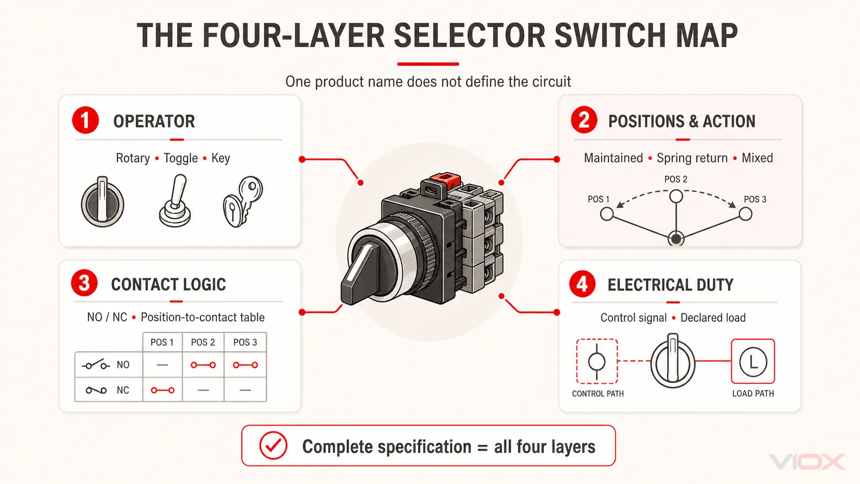
A complete selection needs all four layers. A phrase such as “three-position selector switch” identifies only part of the requirement.
Rotary and Toggle Are Operator Styles
Rotary selector switch
A rotary selector uses a knob or handle that turns through defined positions. It is common where position markings such as HAND–OFF–AUTO, LOCAL–REMOTE, or 1–0–2 should remain visually clear on the panel.
The rotary operator may actuate modular contact blocks immediately behind the panel. In other products, a shaft and cam stack coordinate several contacts. Both rotate, but their construction, circuit duty and selection process may differ.
Toggle selector switch
A toggle selector uses a lever that flips between positions. It can provide a compact, decisive human interface for simple state selection. Depending on the exact device, it may be maintained, momentary, center-off, single-pole or multi-pole.
The lever does not prove that a toggle switch is low-current, nor does a rotary handle prove that a switch is suitable for power switching. Compare declared contact arrangements and electrical ratings rather than judging by the front operator.
For a focused selection between these operator families, see rotary cam switch vs toggle switch.
Maintained, Spring-Return and Mixed Action
Operator action is independent of whether the front mechanism is rotary or toggle.
| Action | Behavior after release | Typical control purpose |
|---|---|---|
| Maintained | Remains in the selected position | Operating-mode selection or a state that must remain visibly selected |
| Spring return to center | Returns from a side position to the center | Temporary command such as jog, raise/lower or a momentary request |
| Spring return to one side | Returns from one position to a defined resting position | A temporary alternate command |
| Mixed action | Some positions remain selected while another returns | A combined mode-selection and temporary-command interface |
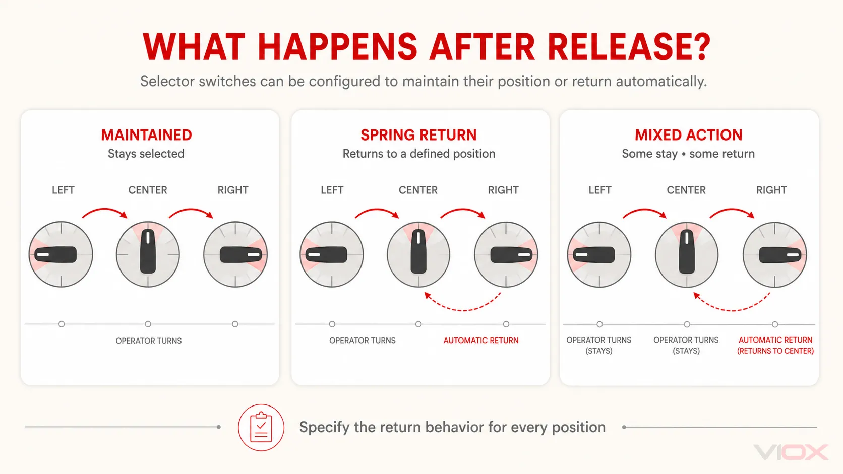
An official product example, Schneider Electric’s ZB4BD5 selector-switch head, is described as a three-position spring-return operator. It illustrates one available configuration; other products use maintained or mixed action.
Specify the return behavior position by position. “Momentary selector” can still be ambiguous if the buyer does not know whether the left position, right position or both return to center.
Position Count Does Not Define the Contact Logic
A two-position selector may control one contact, several contact blocks, or a mechanically coordinated set. A three-position operator may have an electrically open center, maintain one circuit through the center, or produce another pattern defined by its cam or contact blocks.
Create a position-to-contact table before selecting a part:
| Contact path | LEFT | CENTER | RIGHT |
|---|---|---|---|
| Contact A | Open | Open | Closed |
| Contact B | Closed | Open | Open |
| Contact C | Open | Closed | Closed |
This is only a format example, not a universal selector-switch circuit. Populate the table from the actual control schematic. The candidate device must reproduce the required states exactly.
NO and NC contact blocks
A normally open (NO) contact is open in its defined normal condition; a normally closed (NC) contact is closed in that condition. “Normal” must be interpreted using the manufacturer’s operator and contact diagrams, usually with the device unactuated or in its defined reference position.
For a fuller explanation of normal-state conventions, read what NO and NC mean.
Selector Switch vs Rotary Cam Switch
A rotary cam switch can perform a selector function, but not every selector switch is a rotary cam switch.
| Feature | Modular control selector | Rotary cam switch |
|---|---|---|
| Primary role | Human interface for selecting control states | Mechanically programmed switching across one or more contact sets |
| Typical construction | Front operator, fixing collar and one or more contact blocks | Handle and shaft driving profiled cams and contact stages |
| Contact configuration | Built from compatible NO/NC or other control contact blocks | Defined by a position-specific cam program |
| Common circuit context | PLC input, relay logic, contactor coil or signalling circuit | Control, measurement or declared load-switching duty depending on product |
| Selection object | Operator/action plus contact-block arrangement | Full switching program plus electrical duty |
Use a modular selector when the main need is a clear control-panel interface and compatible contact blocks can create the required logic. Use a rotary cam switch when several contacts must follow a defined mechanical program or when the exact product provides the declared switching duty required by the circuit.
The VIOX cam switch vs rotary switch guide explains the adjacent terminology: rotary describes operation, while cam describes an internal contact-actuation mechanism. For a broader product overview, use the rotary cam switch guide.
Control-Circuit Duty and Direct Load Switching Are Different Jobs
Most selector-switch errors begin when a control-panel operator is treated as though it were automatically a load switch.
In a common control architecture, the selector switch sends a command to a programmable logic controller (PLC), control relay or contactor coil. The downstream device performs the power switching. Selection therefore depends on control-circuit characteristics and the compatibility of the operator, contact blocks and controlled input or coil.
In another architecture, a cam switch may make or break a declared load directly. That requires a product with ratings and a switching duty appropriate to the voltage, current and load type. The device may look similar from the front while belonging to a different product-standard scope.
IEC 60947-5-1:2024 applies to electromechanical control-circuit devices and switching elements used for functions such as controlling, signalling and interlocking. IEC 60947-3:2020 applies to switches, disconnectors, switch-disconnectors and fuse-combination units within its scope. The exact manufacturer documentation determines which declarations apply to a particular device.
An ordinary selector switch must not be assumed to provide an isolation function or an emergency-stop function. Those tasks require purpose-designed equipment and a system assessment under the applicable standards and local requirements.
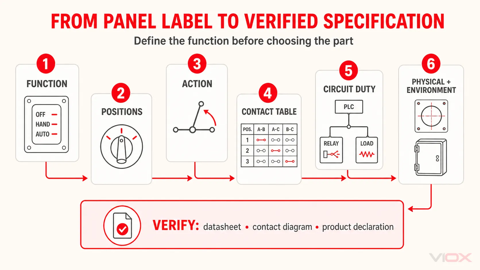
How to Specify a Selector Switch
Use the following sequence to turn a panel label into a usable specification.
1. Define the circuit function
State what the operator commands: mode selection, local/remote control, a temporary motion command, measurement selection or another defined function.
2. Name every position
Record the number, order and label of positions. Include the rotation angle or lever arrangement when it affects panel compatibility or operator use.
3. Define action at each position
State maintained, spring return to center, spring return to a side, or mixed action. Do not use “momentary” without identifying the return position.
4. Build the contact table
List every required contact path and mark its state in every operator position. Then select compatible contact blocks or a cam program that reproduces it.
5. Identify the controlled circuit
Record AC or DC, voltage, expected current, load type and whether the switch operates a PLC input, relay, contactor coil, measurement path or load directly.
6. Verify the physical interface
Check panel cutout, panel thickness, front dimensions, available rear depth, terminal access, legend plate, key or handle style, and compatible contact-block mounting.
7. Verify the environment and evidence
Specify any front-of-panel or enclosure protection needed for the installed assembly. Request the exact datasheet, contact diagram, product-standard declaration and model-specific instructions. Do not transfer ratings from a similar-looking series.
Selector Switch Specification Worksheet
| Specification field | Project requirement |
|---|---|
| Function and labels | ______________________________ |
| Operator style | Rotary / toggle / key / other |
| Number and order of positions | ______________________________ |
| Action at each position | Maintained / spring return / mixed |
| Position-to-contact table | Drawing or schedule reference: __________ |
| Controlled circuit | PLC input / relay / contactor coil / signal / direct load |
| Voltage, current and load type | ______________________________ |
| Required product-standard evidence | ______________________________ |
| Panel cutout and rear depth | ______________________________ |
| Environmental or access-control need | ______________________________ |
| Required documentation | Datasheet / diagram / conformity evidence / instructions |
After completing the worksheet, route a control-interface requirement to the VIOX control and signalling device family. Route a mechanically programmed or declared load-switching requirement to the cam switch and rotary switch family.
Frequently Asked Questions
Is a selector switch the same as a rotary switch?
Not always. Selector describes the function of choosing between states; rotary describes the movement of the operator. Many selector switches are rotary, but rotary switches also include devices used for other functions.
Can a selector switch have more than three positions?
Yes. Position count is product- and application-specific. Two- and three-position control selectors are common, while cam and instrumentation selectors may have more positions. Verify the exact switching program and markings.
Is a selector switch maintained or momentary?
It can be either, or it can use mixed action. Define what every position does after the operator releases it.
Can a selector switch control a motor directly?
Only if the exact device is declared and rated for that motor-circuit switching duty. Many panel selector switches only command a contactor, relay or PLC input and should not be treated as direct motor switches.
What is a HAND–OFF–AUTO selector switch?
It is a three-state operator used to select manual control, an off state and automatic control. The words do not define the internal contacts; use the control schematic to specify the contact state required in each position.