On this page
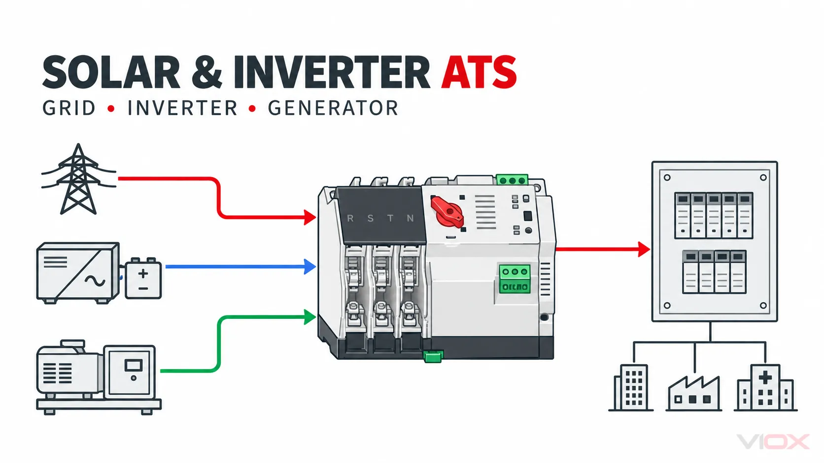
A solar automatic transfer switch normally switches AC sources: grid AC, an inverter’s AC backup/EPS output, or generator AC. It does not normally switch the raw DC input from PV strings. PV modules feed a DC-rated isolating and protection path into the inverter; the inverter converts DC to AC; transfer equipment then selects between compatible AC sources for a defined load.
Fast answer: First check whether the hybrid inverter already includes grid bypass, an EPS/backup output, and a dedicated generator input. If it does, an external ATS may be unnecessary or may belong at a different system boundary. Add an ATS only when the inverter manual, ATS documentation, grounding design, protection scheme, and approved single-line diagram support the exact architecture.
Which Solar or Inverter Transfer Architecture Fits?
| Intended function | Typical architecture | Main verification |
|---|---|---|
| Keep essential loads powered from battery during a grid outage | Grid and battery feed a hybrid inverter; its backup/EPS output supplies an essential-load panel | Internal transfer function, backup-output limits, islanding method, neutral and protection |
| Select grid AC or inverter AC output for one load bus | Grid AC + inverter backup AC → external ATS → critical-load panel | Sources must be compatible with ATS ratings; prevent unintended backfeed; verify inverter operating mode |
| Let a generator support a hybrid inverter | Grid or generator AC → approved source-selection arrangement → inverter AC input | Inverter accepts generator waveform/range; source selection and start logic are documented |
| Select inverter AC or generator AC for critical loads | Inverter AC + generator AC → ATS → critical-load panel | Never parallel unsynchronized sources; verify neutral, protection, transfer timing and load capability |
| Switch PV string conductors | Use DC-rated PV switching/protection designed for the array | A normal AC ATS is not the correct device |
The Essential Boundary: PV DC Is Not ATS AC
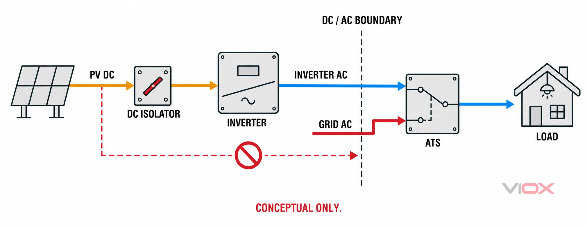
The U.S. Department of Energy explains that an inverter converts the DC electricity from solar panels to AC electricity used by the grid and most loads. That conversion boundary matters: a product described only as a low-voltage AC transfer switch should not be placed in a PV-string DC circuit.
PV DC switching has different arc-extinction, polarity, voltage, connector, isolation, and protection requirements. Use a DC isolator, combiner, fuse, breaker, or contactor only where its markings and instructions cover the specific PV circuit. “Solar ATS” is a system-use phrase; it is not proof that every current path inside the system is suitable for PV DC.
When the Inverter Already Performs the Transfer
Many hybrid or storage inverters include one or more of these functions:
- a grid AC input and internal bypass;
- a separate backup or EPS output;
- a battery-supported islanding function;
- a dedicated generator input;
- internal source qualification and transfer logic;
- generator remote-start control.
In that architecture, adding a second ATS can duplicate interlocking, create an unintended neutral path, interrupt inverter operation, or conflict with the inverter’s control logic. Treat the inverter manufacturer’s approved single-line diagrams as the starting point.
An external ATS is generally not justified merely because the site has solar panels. Grid-connected PV without a properly designed islanding and backup function normally stops supplying an isolated building during a utility outage. Battery storage alone also does not prove that the system can form and regulate an islanded AC bus; that function must be documented for the inverter and system design.
Three Practical AC-Side Architectures
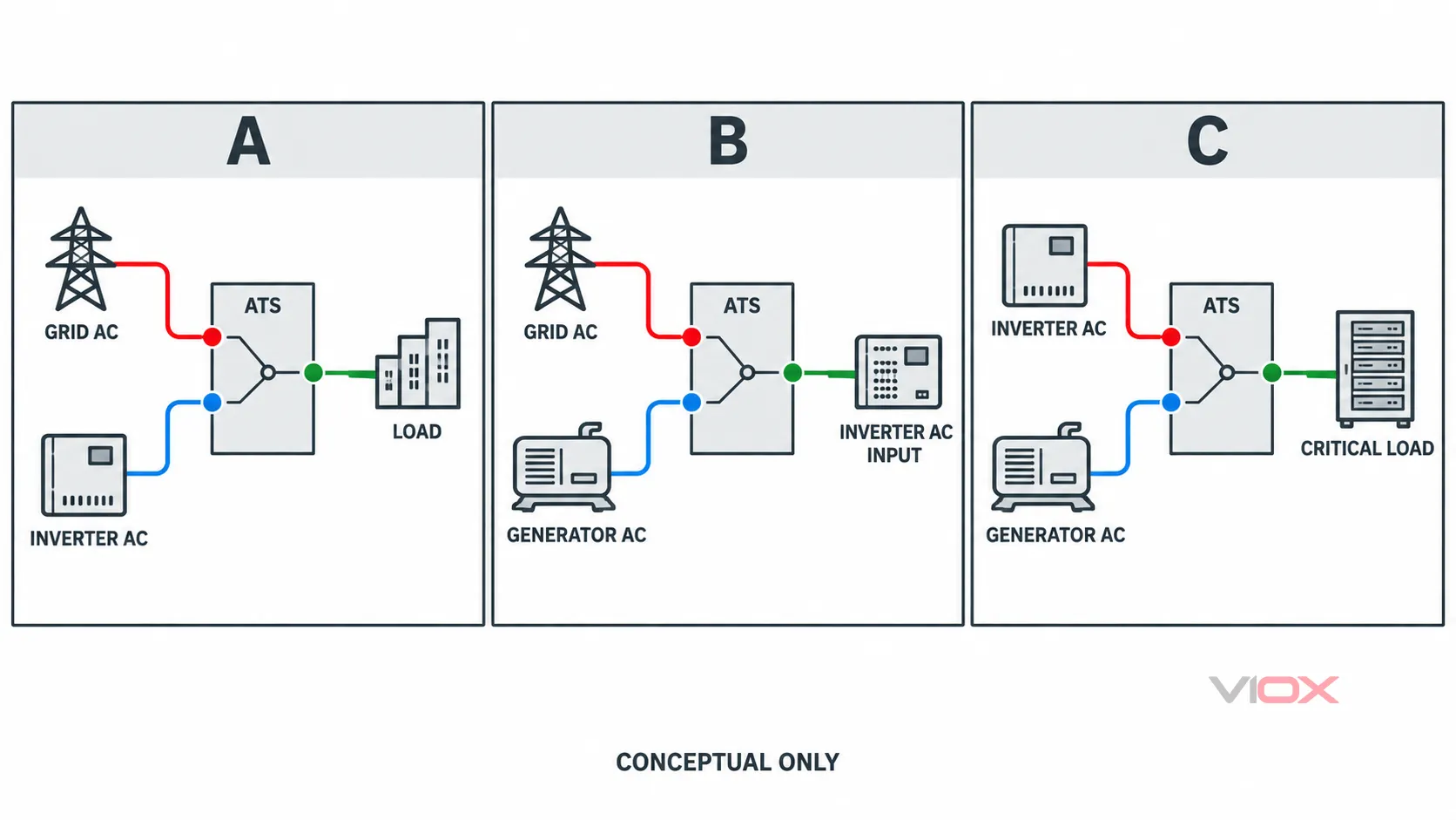
Architecture A: Grid AC versus inverter backup output
Here, the external ATS selects between grid AC and a dedicated inverter backup/EPS output for a critical-load panel. This can be valid when the inverter documentation permits the output arrangement and both sources match the ATS voltage, frequency, phase, pole, current, and fault-duty limits.
Do not connect the inverter’s ordinary grid-following output as if it were an independent backup source. The selected output must be designed to energize the intended loads while islanded.
Architecture B: Grid AC versus generator AC feeding the inverter
Some hybrid inverters can accept either grid or generator power at an AC input. Source selection may occur inside the inverter, in approved external equipment, or in a coordinated switchboard. Confirm the inverter’s accepted voltage/frequency window, generator minimum capacity, charging-power limit, power-quality tolerance, neutral arrangement, and any required warm-up delay.
If a generator remote-start output is used, the ATS or inverter controller may issue the command. Avoid two independent controllers trying to start, stop, or qualify the same generator without an engineered sequence.
Architecture C: Inverter AC versus generator AC feeding critical loads
An ATS may select the inverter’s island-capable AC output or generator AC for a critical-load bus. The interlock must prevent unintended source connection. The generator must support the transferred loads and the inverter output must tolerate the selected transition. Check whether either source can feed power backward through connected equipment.
For a generator’s full failure-to-cooldown sequence, see Automatic Transfer Switch for Generator.
Neutral Switching and Bonding
Neutral design depends on the sources and protective scheme. Important questions include:
- Does the inverter connect neutral internally in each operating mode?
- Is the generator neutral bonded to its frame or system earth?
- Where is the installation’s neutral-to-earth bond located?
- Does the inverter create or switch a neutral bond during island operation?
- Which RCD, GFCI, residual-current, or ground-fault devices must operate in each source state?
- Does the ATS switch neutral, and is that behavior compatible with every state?
A 4-pole ATS is not universally mandatory, and a solid neutral is not universally correct. The system designer must map each source state—grid connected, inverter island, generator supplied, bypass, maintenance—and show the neutral and protective-earth paths in each one. Protective earth normally remains continuous rather than passing through ordinary transfer contacts.
Use Single-Phase vs Three-Phase ATS: 2P, 3P or 4P for the deeper pole-selection framework.
Generator Two-Wire Start in a Solar/Storage System
“Two-wire start” commonly means a maintained volt-free contact that requests generator operation, but it is not a universal wiring standard. The controller may be the inverter, the ATS, an energy-management system, or a dedicated genset controller.
Verify:
- which controller owns the start/stop decision;
- contact type, normal state, voltage/current rating, and isolation;
- generator warm-up, source-acceptance, retransfer, and cooldown timing;
- low-battery state-of-charge thresholds and charging limits;
- failure behavior if communications or sensing is lost;
- exact terminals and firmware mode in both manuals.
Do not use a generic internet diagram as a terminal schedule. The ATS Wiring Diagram reference explains power, sensing, control, neutral, and PE layers, but the approved product drawings govern field connections.
Sizing and Protection Checks
ATS current is based on transferred AC load
Size the ATS from the AC current it carries at its installed point, under its marked conditions. Do not size an AC ATS from PV-array DC current. Account for continuous load, inverter overload capability, motor inrush, generator step-load capability, temperature, enclosure, utilization category, and any load shedding.
Source protection remains necessary
An ATS may select sources without providing all required overcurrent protection. Document protective devices on the grid, generator, inverter, battery, and PV sides. Verify available short-circuit current at the ATS and its declared short-circuit rating or withstand/closing rating under the specified upstream device.
The inverter can limit fault current differently from the utility or generator. Protection must still disconnect faults under every operating state. Check selectivity and minimum fault current as well as maximum duty. The ATS–Circuit Breaker Coordination Guide covers the transfer-switch side of that evidence chain.
Transition behavior must suit the electronics
Open transition is a common starting point because it prevents intentional source overlap, but it creates an interruption. Confirm how the inverter, generator, contactors, motors, UPS equipment, and sensitive loads respond. Closed transition or source paralleling requires equipment and controls specifically designed for synchronization and the required approvals; it must never be improvised with a standard ATS.
VIOX Model Evidence: What Is Actually Supported?
The VIOX VOQ4-100E product page explicitly describes solar/grid integration and publishes an AC-side specification table including 2P/3P/4P configurations, PC class, AC 400 V operating voltage, AC 220 V control voltage, 50 Hz, and 16–100 A current options.
That evidence supports considering the model only for a matching AC transfer application. It does not establish:
- suitability for raw PV-string DC;
- compatibility with every hybrid inverter or generator;
- suitability for a 60 Hz system;
- a particular neutral/bonding arrangement;
- adequate fault duty or upstream-protection coordination for a project;
- certification for every destination market.
Also verify the latest datasheet and exact order code: marketing summaries can be broader than a specification table, and the tighter documented limit should govern until VIOX confirms otherwise.
Solar/Inverter ATS Design Checklist
| Category | Information required before selection |
|---|---|
| Architecture | Approved single-line diagram and reason an external ATS is needed |
| Sources | Grid, inverter AC output, generator AC; voltage, phase, frequency and grounding |
| PV/battery boundary | DC voltage/current and separate DC isolating/protection equipment |
| Inverter | Exact model, operating mode, bypass/EPS/generator functions, output and overload limits |
| Generator | Model, neutral bond, waveform limits, start interface, step-load performance |
| Loads | Critical-load schedule, motors, inrush, acceptable interruption and load shedding |
| ATS | AC rating, poles, transition, class, control supply, sensing, enclosure and environment |
| Neutral/PE | Bond locations and paths in every source state; RCD/GFCI/ground-fault behavior |
| Protection | Devices and settings on every source; available and minimum fault current |
| Compliance | Destination rules, certification, utility requirements and approved manuals |
Selection Rule
Choose a solar or inverter ATS only after the AC architecture is fixed. If the inverter already owns transfer and generator control, follow its approved design. If an external ATS is required, select it as part of the complete AC system—not from a “solar” label—and keep PV-string DC within separately rated DC equipment.
VIOX supplies automatic transfer switches for defined low-voltage dual-source applications. Send the inverter and generator manuals, single-line diagram, source/load data, neutral and protection design, required transition sequence, fault-duty information, and destination market for a bounded product-fit review.