

On this page
The main service panel is normally the baseline external AC SPD boundary for a microinverter system. Add an SPD in the AC combiner only when that enclosure creates a distinct protection boundary and the exact microinverter manual, system topology, cable route, exposure, bonding and coordination evidence support it. Using both can be correct, but it is not an automatic default.
This is an architecture decision, not a universal installation recipe. “SPD” here means a surge protective device on the microinverter system’s AC side. A DC SPD or DC-string fuse does not answer where the AC SPD should go, and selecting a higher kA rating does not compensate for an unsuitable location.
Start With the System Boundary, Not the Product Label
Microinverters convert each module’s DC output to AC near the array, so the external power path is different from a central string-inverter system. The U.S. Department of Energy describes microinverters as attached to individual modules and able to support module-level operation; that architecture affects where AC circuits are collected before they reach the service equipment.
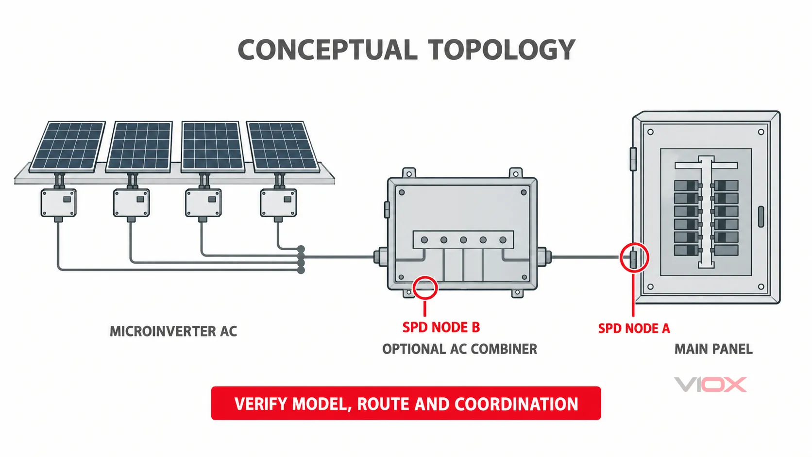
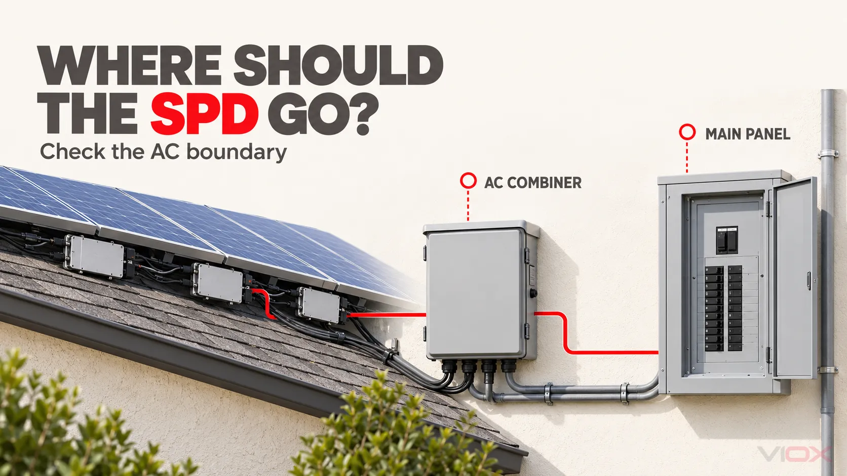
Conceptual topology only. Lines show AC collection relationships, not terminal-level wiring, conductor count, switching arrangements or a mandated device layout.
For placement, draw the actual project first:
- Locate every microinverter or microinverter branch.
- Identify junction points and any separate AC combiner enclosure.
- Follow the AC feeder route to the main service panel or dedicated solar panel.
- Mark each point where the circuit crosses a different enclosure, exposure zone or equipment boundary.
- Overlay the exact microinverter installation manual and the applicable electrical installation requirements.
The drawing prevents a common shortcut: calling every junction box a “combiner” and deciding that it needs an SPD merely because an SPD can be installed there. A bushing, splice enclosure or simple junction box is not automatically a separate surge-protection zone.
The generic guide to SPD locations in electrical panels explains the broader panel-boundary principles. The microinverter decision is narrower: which one of those boundaries is necessary and defensible in this AC topology?
Why the Main Panel Is Usually the Starting Point
The main service panel or dedicated photovoltaic supply panel is often the first common AC power boundary before the microinverter feeder connects with the building’s electrical distribution. It is accessible, contains or coordinates circuit protection, and is normally the point at which the installer must verify service voltage, available fault current, bonding and the applicable connection rules.
That makes it the default candidate for external AC surge protection in a typical system where the microinverter branch circuits are collected and run directly to that panel.
The word “default” still has conditions. The SPD must be suitable for:
- the actual AC system voltage and connection configuration;
- the available short-circuit current and required backup protection;
- the expected surge environment and equipment withstand;
- the enclosure and mounting arrangement;
- the microinverter manufacturer’s written installation requirements;
- the bonding and conductor-routing method required for effective operation.
An SPD is not a substitute for equipment grounding and bonding. IEC 61643-12 covers SPD selection, operation, location and coordination, and its existence is a reminder that placement and connection details are part of protection performance, not an afterthought.
Main-panel-only protection deserves serious consideration when the AC combiner is close to that panel, the feeder stays within one ordinary equipment zone, the system manual does not require a second SPD, and a qualified assessment shows no separate local exposure that warrants another device. In that case, installing a second SPD “for safety” can add components, failure points and coordination work without a documented reason.
When an AC-Combiner SPD Earns Its Place
An AC-combiner SPD becomes a stronger candidate when the combiner is more than an electrical label. It may:
- serve as a separate equipment enclosure with branch or feeder terminations;
- be electrically remote from the main panel;
- be installed in a more exposed location;
- create a useful service or verification point near the microinverter AC collection;
- form a boundary identified by the exact system manual or project design;
- reduce the need to route every protection consideration back to a distant panel.
Those conditions still do not prove that an SPD is required. The designer must show why local protection changes the relevant surge exposure or equipment overvoltage risk. IEC 61643-32 provides application context for surge protection in photovoltaic installations, including the AC side, but its scope should not be turned into a blanket instruction to place an SPD in every combiner.
Site exposure can include a long AC route, nearby lightning activity, outdoor enclosures, elevated structures or a building layout that concentrates switching and surge energy differently from a compact indoor installation. Do not reduce that assessment to a universal cable length. The actual route, enclosure, bonding path and manufacturer instructions matter.
The same caution applies to North American projects. UL 1449 Edition 5 is the current published UL standard for surge protective devices and covers AC systems and PV equipment within its stated scope, but a standard title alone does not approve a product for a particular location, voltage, connection or available fault current. Verify the listed product and its instructions.
When “Both” Is the Defensible Choice
“Both” means more than buying two SPDs. It means protecting two identified boundaries with devices that are compatible with the system and coordinated with each other.
A two-location design can be justified when:
- the exact microinverter manual requires SPDs at both the electrical panel and the AC combiner for the selected model;
- the combiner is a genuinely separate, exposed or remotely located equipment boundary;
- the conductor route and enclosure arrangement create a local protection need that the main-panel device alone does not address;
- the two devices have compatible voltage and surge-duty ratings for their respective locations;
- the bonding arrangement supports both installations;
- the designer can document energy coordination and backup protection rather than simply adding another cartridge.
This is where model-specific evidence matters. Installation manuals can differ by product family, firmware-controlled configuration, grid profile, wiring topology and market. A requirement printed for one microinverter series is not a universal VIOX recommendation and does not establish compatibility with every AC combiner.
It is equally wrong to assume that two SPDs automatically improve protection. A downstream device with an unsuitable voltage rating, excessive lead length, poor bonding or uncoordinated short-circuit protection can introduce another failure point. The SPD coordination and cascading guide explains why two protective stages must be selected as a system.
Use the AC-combiner product page only after the architecture has been decided. VIOX’s combiner-box family should be evaluated against the project’s exact drawings, environmental rating and microinverter documentation; this article does not claim that every VIOX enclosure is a verified microinverter AC combiner.
Main Panel, Combiner or Both?
| Project condition | Main panel | AC combiner | Both |
|---|---|---|---|
| Microinverter AC circuits are collected and run directly to the service panel, with no separate exposed boundary | Strong default candidate | Usually not justified without model or site evidence | Not automatic |
| Separate AC combiner is close to the main panel and inside the same ordinary equipment zone | Still the baseline | Evaluate only if the exact manual or design establishes a local requirement | Only when coordination and two distinct boundaries are documented |
| Remote or more exposed AC combiner creates a separate protection boundary | Keep as the upstream candidate | Possible local candidate | Often the configuration that deserves detailed study |
| Selected microinverter manual explicitly marks SPDs at both locations | Required as part of the system design, subject to the manual | Required as part of the system design, subject to the manual | Follow the exact model instructions and applicable installation rules |
| Only a generic desire for “extra protection” exists | Do not skip the engineering assessment | Do not add by habit | Do not treat quantity as proof of quality |
The matrix is a starting point. A final design still needs the actual equipment model, single-line diagram, cable route, enclosure locations, bonding method and prospective fault current.
The Evidence That Can Change the Answer
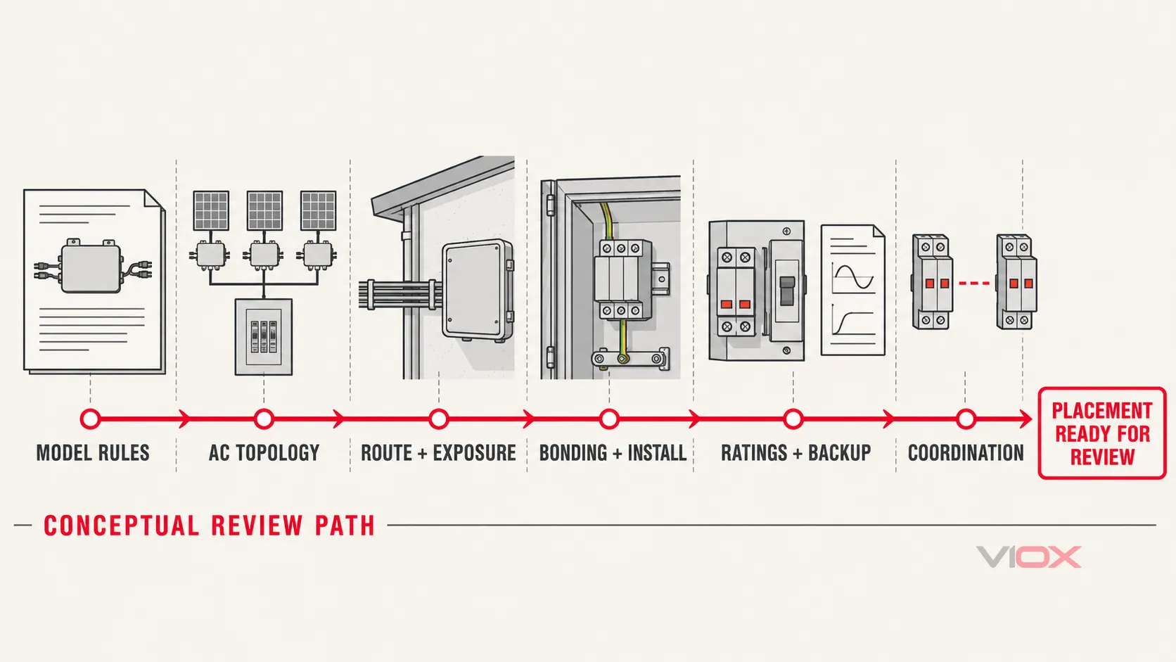
The sequence is a review method, not an electrical circuit. Each gate must be supported by project documents before the next assumption is accepted.
1. Exact Microinverter Model and Manual
Record the series, model code, market variant and manual revision. Check the AC output configuration, permitted overcurrent protection, connection topology and any explicit SPD instruction. Do not extrapolate from a different inverter family or from a competitor’s diagram.
If the manual is silent, do not turn silence into a prohibition or a requirement. Ask the manufacturer for a written position when the project needs a two-location design.
2. AC Topology and Enclosure Function
Confirm whether the “combiner” contains only splices, or whether it is a defined AC collection enclosure with feeder terminations, switching, protection or other equipment. Mark the exact point where each microinverter branch is combined.
The distinction between an AC and DC combiner is fundamental. The VIOX guide to AC versus DC combiner boxes covers the architecture; this page does not repeat its full comparison.
3. Route and Exposure
Document the AC route length, indoor or outdoor sections, enclosure exposure, nearby tall structures, cable method, separation from other circuits and any known surge history. A long route is a reason to investigate, not an automatic placement rule.
The original forum report that prompted this topic described lost microinverters after reported surges. It remains an unverified user observation: damaged equipment does not by itself prove the surge source, path or required mitigation. Use it to ask better questions, not as a failure analysis.
4. Bonding and Physical Installation
Review the equipment bonding path, enclosure continuity, SPD connection route and the need to keep protective current paths short and controlled according to the manufacturer’s instructions. A protector with excellent headline ratings can perform poorly if its connection creates a large loop or a poor bond.
Where the SPD is installed inside a combiner, verify that the combiner is suitable for the environmental and electrical service conditions. The solar combiner protection design guide provides the broader enclosure-level context.
5. SPD Ratings and Backup Protection
For each candidate location, compare:
- maximum continuous operating voltage and system-voltage compatibility;
- nominal discharge current and impulse-current capability where the surge-risk assessment calls for it;
- voltage protection level against the equipment’s withstand capability;
- short-circuit current rating and the manufacturer’s specified backup protection;
- number of poles, protection modes and connection topology;
- status indication or remote signalling needed for maintenance;
- suitability for the enclosure, temperature and pollution conditions.
Do not copy one voltage rating from another project. Do not assume that a larger surge-current number makes a device universally better. The correct comparison is the complete electrical duty at that location.
6. Coordination and Existing Protection
If both locations are used, the upstream and downstream devices must be checked together. Review the manufacturer’s coordination data, backup fuses or breakers, conductor lengths, separation and the possibility that one SPD changes the fault current seen by another.
The main-panel SPD and the AC-combiner SPD should each have a defined purpose. If the second device cannot be shown to protect a distinct boundary or cannot be coordinated with the first, the design is not stronger simply because it contains more hardware.
The solar power system SPD selection guide can support the wider PV protection study, while the SPD definition hub can resolve terminology before the procurement list is built.
RFQ and Design-Review Checklist
Provide the following to the SPD and enclosure supplier when requesting a review:
- Microinverter make, model, market variant and installation-manual revision.
- Single-line diagram showing module-level inverters, AC branch collection, optional combiner and main panel.
- Nominal AC voltage, phase configuration and expected maximum continuous voltage.
- Prospective short-circuit current at each proposed SPD location.
- Existing upstream breaker or fuse type, rating and curve.
- AC route length and a sketch showing indoor, outdoor and enclosure transitions.
- Main-panel and combiner enclosure dimensions, mounting method and environmental ratings.
- Bonding and equipment-grounding arrangement.
- Exact surge environment or project requirement used to select the SPD class and duty.
- Whether the microinverter manual explicitly requires one SPD location or multiple locations.
- Proposed SPD model, voltage rating, discharge-current rating, voltage protection level, short-circuit rating and backup protection.
- Written coordination evidence for a two-SPD design.
The expected deliverable is not merely a quotation for two boxes. It is a reviewed bill of materials that matches the diagram, each location’s electrical duty and the instructions for the selected equipment.
The VIOX SPD product family can then be checked against those requirements. The correct outcome may be a main-panel SPD alone, a main-panel plus coordinated combiner SPD, or a redesigned topology in which a different equipment boundary is more appropriate.
Sources and Standards
- IEC 61643-01:2024: general requirements and test methods for low-voltage surge protective devices.
- IEC 61643-11:2025: requirements and test methods for surge protective devices connected to AC low-voltage power systems.
- IEC 61643-12:2020: guidance on SPD selection, operation, location and coordination.
- IEC 61643-32:2017: SPD application context for photovoltaic installations, including the PV AC side within the standard’s scope.
- U.S. Department of Energy: Solar Photovoltaic System Design Basics: module-level microinverter context.
- UL 1449 Edition 5: current UL standard scope for surge protective devices.