

On this page
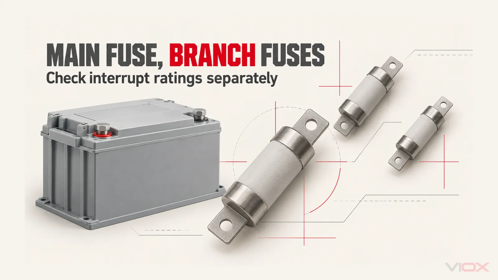
Not automatically. A main battery fuse with a high interrupt rating does not transfer that rating to downstream branch fuses. Each branch fuse must be suitable for the DC voltage and available fault current at its location, unless an applicable, documented protection combination establishes another permitted arrangement. The main fuse’s ampere rating, its breaking capacity and its current-limiting performance are different things.
For a battery-fed distribution panel, keep three checks separate:
- Can each protective device safely interrupt the fault duty it may encounter?
- Will the protection clear damaging overcurrents before the affected conductors and components exceed their limits?
- Will a branch fault leave the healthy branches energized, if selective operation is required?
A design can meet one of these conditions and fail another. A large main fuse and a small branch fuse do not, by themselves, answer any of them.
What the Main and Branch Ratings Actually Prove
An interrupt rating, also called breaking capacity, describes a device’s ability to interrupt a specified fault current under its declared conditions. It must be read with the voltage, AC/DC duty and applicable test conditions. It is not the current at which the fuse starts to melt.
| Item | What it tells you | What it does not establish |
|---|---|---|
| Fuse ampere rating | The fuse’s rated current under specified conditions | An instantaneous opening threshold or a maximum possible circuit current |
| DC voltage rating | The DC voltage duty for which the device is specified | Permission to use an AC-only rating in a battery circuit |
| Interrupt rating | The fault current the fuse is rated to interrupt under stated conditions | The interrupt rating of another fuse downstream |
| Time-current characteristic | Melting or clearing behavior versus overcurrent, depending on the curve | Complete high-current backup protection for an arbitrary combination |
| Peak let-through and clearing I²t | Relevant current-limiting and thermal-stress information under specified conditions | Automatic acceptance of every downstream component |
In US workplace installations, OSHA 1910.303(b)(4) requires fault-interrupting equipment to have sufficient interrupting capability for the voltage and current available at its line terminals. The adjacent coordination requirement also addresses circuit impedance and component short-circuit ratings. This is a useful statement of the design issue, not a substitute for the installation rules governing a particular boat, vehicle or stationary battery system.
The fuse family also matters. An automotive blade fuse, an industrial cylindrical fuse and a battery fuse cannot be treated as interchangeable because their ampere ratings match. Use the electrical fuse guide for the broader family and rating distinctions.
Why the Main Fuse Is Not a Fixed Current Ceiling
Consider a single battery source feeding a main fuse, a common distribution point and several fused branches. For a fault downstream of one branch fuse, the battery contribution passes through both that branch fuse and the main fuse. The main fuse also carries any current still supplying the other branches.
Both devices therefore encounter the fault event. They do not wait for one another to decide whether the event is safe. Their different elements and operating characteristics determine how they heat, melt, arc and interrupt.
The following assumptions are unreliable:
- A 300 A main fuse does not clamp every fault to 300 A.
- A 20 kA interrupt rating does not mean the main fuse limits current to 20 kA.
- A 10 A branch fuse is not guaranteed to clear safely before a larger main fuse merely because 10 is smaller than 300.
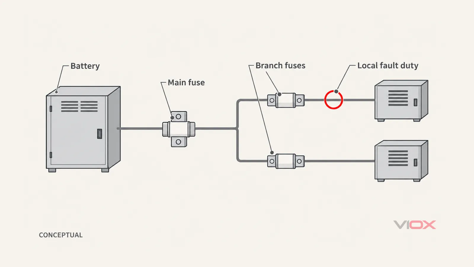
Conceptual single-source distribution relationship. The marked branch location identifies where local fault duty is assessed. Lines show equipment order, not terminal wiring or a complete fault-return path; return conductors and installation details are omitted.
A fuse can begin melting without having completed interruption. An arc can conduct during the clearing process. Consequently, knowing which element melts first does not establish whether either device can safely interrupt the event.
Current limitation can help, but it is an operating behavior within specified conditions. UL’s Panelboard Application Guide gives an AC current-limiting definition and describes identified panelboard series combinations. Those examples do not establish DC battery performance. A high interrupt rating alone does not state the main fuse’s peak let-through current, clearing energy or performance with a particular branch device.
An Illustrative Rating Check: 20 kA Main, 1 kA Branch
Assume the following hypothetical design inputs. These are not VIOX product ratings, test results or a recommended fuse combination:
- Maximum system voltage for this example: 60 V DC.
- Main fuse: 300 A, with a declared interrupt rating of 20 kA at the relevant DC conditions.
- Branch fuse: 10 A, with a declared interrupt rating of 1 kA at the relevant DC conditions.
- Prospective available fault current at the branch fuse location: 6 kA, established by the assumed system study before crediting either fuse’s current-limiting action.
- No applicable backup-combination evidence has been supplied.
The branch check is:
Branch interrupt rating = 1 kA
Available branch fault current = 6 kA

1 kA < 6 kA
The branch fuse does not meet the individual interrupt-rating check. The main fuse’s 20 kA rating does not repair that mismatch. Its own duty must also be checked at its own location; the 6 kA branch value does not establish the fault duty at the battery or main fuse.
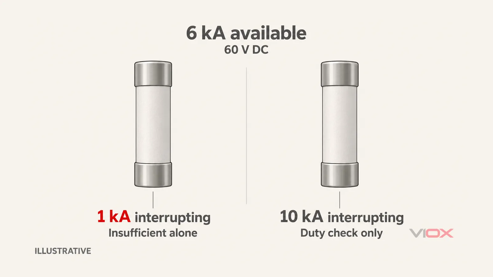
Illustrative numbers only. Both comparisons assume the relevant 60 V DC conditions. The 6 kA value is prospective available current before crediting fuse current limitation, not measured let-through. The 10 kA case exceeds that duty for this single rating check; it is not a complete product-selection or installation approval.
If an alternative branch fuse had a verified 10 kA DC interrupt rating under the applicable conditions, then 10 kA would exceed the assumed 6 kA duty. It would not have to match the main fuse’s 20 kA solely for this comparison. Voltage suitability, operating characteristic, conductor protection, holder compatibility and the remaining system requirements would still need verification.
Neither comparison predicts a clearing time. Without exact device data, it would be misleading to claim that the main fuse opens in a few milliseconds, that the branch fuse survives, or that the two devices operate selectively.
Do All Branch Fuses Need the Main Fuse’s Interrupt Rating?
No. The relevant comparison is between each device’s verified capability and its local duty, not whether all fuse labels show the same kA number.
A fault at a distribution point near a battery can have a different available current from a fault at the end of a branch. Source impedance, outgoing and return conductors, connections and fault location affect the loop. A small load’s normal current does not determine the current available during a short circuit.
For a deliberately simplified, single-source resistive model:
Prospective fault current ≈ source voltage / total fault-loop resistanceThis relationship explains why location matters. It is not a complete battery fault-current study. Real verification may need source dynamics, inductance and DC time constant, state of charge, temperature, parallel sources and the fault contribution of connected equipment. Use suitable battery/source information and an accepted engineering method rather than estimating from ampere-hours alone.
Do not assume that long or thin wiring makes a low-interrupt-rating fuse acceptable. Any impedance credited in the study must be justified alongside ampacity, voltage drop and fault-clearing requirements. Deliberately undersizing cable or adding improvised resistance is not a protection solution.
A battery upgrade, added parallel battery or changed cable arrangement can invalidate an earlier assessment. Recheck affected devices when the available fault current or source configuration changes. Do not credit a battery management system’s advertised current limit as a short-circuit interruption guarantee without applicable system evidence.
When Can Backup Protection Be Credited?
Backup protection means that an upstream protective device contributes to the safe clearing capability of a specified downstream arrangement. It requires evidence for that arrangement; it is not established by placing a high-kA fuse upstream.
For example, UL’s panelboard guidance describes lower-interrupt-rating circuit breakers used with specific upstream devices and marked combinations. That example concerns the documented equipment application. It does not validate a DC battery main fuse paired with an arbitrary automotive branch fuse.
If a supplier proposes a backup arrangement, request documentation that addresses:
- The exact upstream and downstream catalog numbers, fuse ratings and permitted substitutions.
- The DC voltage and fault-current conditions covered, including any relevant time-constant limits.
- The applicable combination test, certification or accepted engineering basis for the intended equipment and market.
- Required holders, distribution components, installation conditions and replacement identification.
- What the evidence proves: safe interruption, component protection and/or selectivity, including the limits of each claim.
Peak let-through or I²t data may form part of an engineering assessment, but comparing two isolated catalog numbers is not automatically a complete combination verification. The behavior of both devices and the affected assembly must be considered. OSHA’s US workplace rules also require marking for equipment applied with manufacturer-marked series combination ratings; replacement identity is part of maintaining that arrangement.
Adding an intermediate fuse simply because its ampere or interrupt rating falls between the existing two does not prove a safe sequence. Each additional device introduces another operating characteristic and another coordination question.
Backup Protection and Selectivity Answer Different Questions
Interruption adequacy asks whether the fault can be cleared safely. Selectivity asks which protective devices operate, so that an affected branch can be disconnected while healthy circuits remain supplied.
If a design relies on the main fuse operating to help clear a severe branch fault, that event can disconnect the other branches too. A backup claim therefore does not establish selective operation. Equally, separating two time-current curves does not, by itself, establish an adequate interrupt rating or a verified backup combination.
Use the exact minimum-melting and total-clearing information, manufacturer coordination data and any required study. The fuse time-current curve guide explains what curve reading can establish and where let-through data or combination evidence becomes necessary.
Decide What Evidence Is Still Missing
| Evidence available | What you can conclude | Next action |
|---|---|---|
| Each fuse’s individual DC interrupt capability covers its verified local duty | The individual interrupt-rating check is satisfied | Complete conductor, equipment, holder, clearing and selectivity checks as applicable |
| A branch fuse’s individual rating is insufficient, but an exact applicable protection combination is documented | Evaluate the arrangement within the document’s scope; do not extend it to other devices or voltages | Verify every condition, the target-market acceptance and replacement identification |
| Local fault duty is unknown, or the only evidence is the main fuse’s high kA rating | Branch interruption adequacy has not been established | Obtain the source study and exact device/combination evidence before accepting the design |
For a product inquiry, record maximum DC voltage, source configuration, available current at each relevant location, normal load and inrush, both fuse identities, operating data, holder details and the required coordination outcome. Check separate AC and DC entries; the AC fuse vs DC fuse guide explains why an AC marking cannot supply missing DC evidence.
IEC 60269-7:2021 provides supplementary product requirements for fuse-links protecting batteries and battery systems up to 1,500 V DC. Its scope is not evidence that any particular fuse or combination is certified, or that it meets a marine, vehicle or stationary-system installation requirement.
Use the VIOX fuse, holder and disconnector range to identify candidate product families, then request model-specific DC ratings and supporting documents. The product-family page alone does not establish a battery backup combination.
Keep fault-current assessment and protection verification with a qualified designer. Do not create an intentional battery short circuit, open an energized fuse assembly or increase a fuse rating to test whether a proposed arrangement works.