On this page
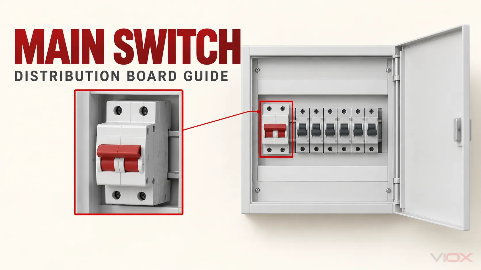
A main switch is the incoming switching device used to disconnect a distribution board’s downstream circuits from a defined supply. The name describes its position and job in the board; it does not by itself tell you whether the device can break load current, provide isolation, or trip on an overload or short circuit. Those functions must be confirmed from the selected device and the completed board design.
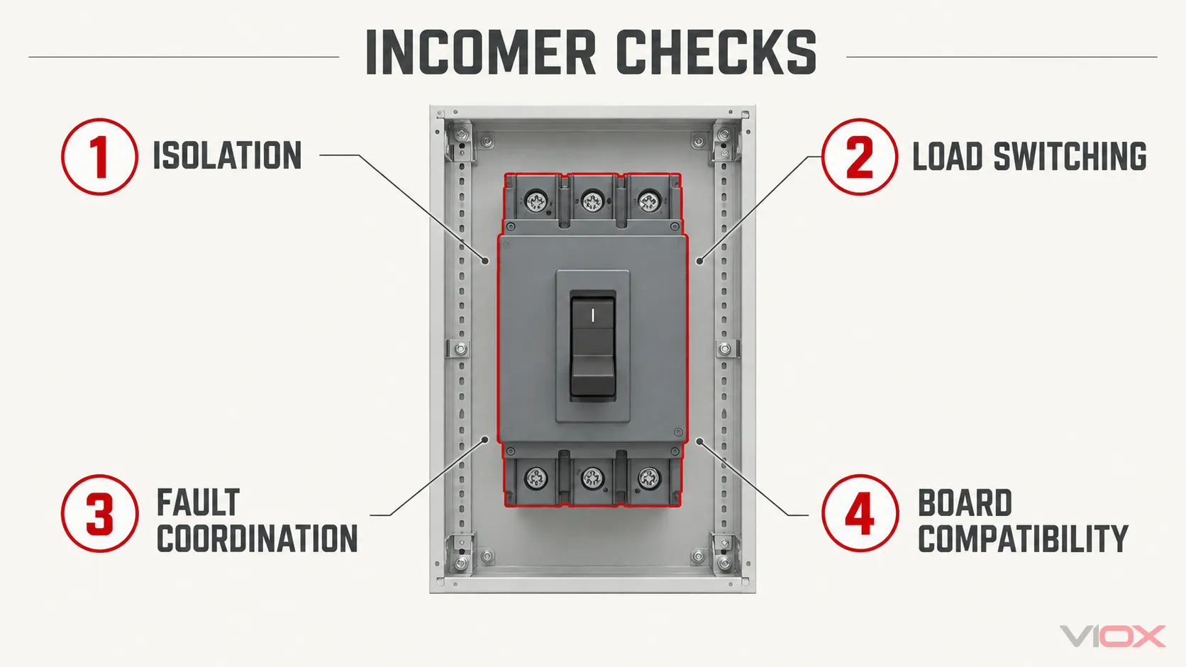
For a new board, first decide what the incomer must do. Then check its voltage, current, number of switched poles, switching duty, short-circuit coordination and compatibility with the board assembly. A main switch that fits the DIN rail is not necessarily a suitable main switch for that board.
| Design input | What to specify or verify |
|---|---|
| Required function | Manual isolation only, normal load switching, or switching plus automatic fault protection |
| Supply arrangement | AC or DC, operating voltage and frequency, earthing system, and every incoming or backfeed source |
| Current and duty | Design current, expected switching frequency, load type, and the device’s declared operational rating |
| Conductors to switch | Pole arrangement based on the actual line and neutral design; never infer it from “single-phase” or “three-phase” alone |
| Fault conditions | Prospective short-circuit current and the device’s documented withstand or conditional rating with its specified upstream protection |
| Board integration | Approved mounting, busbar and terminal interfaces, temperature-rise limits, enclosure, operating access and assembly documentation |
The table is a specification worksheet, not a claim that one product covers every arrangement. For the wider board design, use VIOX’s distribution box selection guide.
Which Parts Does the Main Switch Disconnect?
In a typical one-supply board, the main switch sits between the incoming supply connection and the outgoing protective devices. When a suitable device is opened, its specified downstream conductors are disconnected. The upstream supply cable and incoming terminals may remain energized. A meter, service equipment, generator, photovoltaic (PV) inverter or battery system can also create a different supply boundary from the one a simple front-panel label suggests.
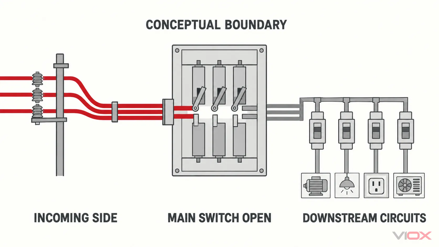
This distinction matters during maintenance. “Main switch OFF” is an operating state, not proof that every accessible part is dead. Identify all sources, use the required isolation procedure, secure against reconnection where necessary, and verify absence of voltage with an appropriate method before work. Electrical Safety First’s isolation guidance explicitly addresses incoming conductors that remain live when a consumer-unit main switch is open.
Nor is a main switch automatically an emergency-stop system. An emergency-stop function depends on the machine or installation’s complete control design, access and required stopping behavior, not the presence of a conveniently located handle.
Main Switch, Switch-Disconnector or Main Breaker?
“Main switch” is an installation role. The actual incoming device may belong to different product families.
| Incoming arrangement | Switching and isolation role | Automatic overcurrent protection? | Key question |
|---|---|---|---|
| Rated switch-disconnector | Makes and breaks its declared normal load and provides the specified isolation function | No | Is its load-switching category and short-circuit coordination suitable? |
| Disconnector used only for isolation | Provides its declared isolation function | No | Is it being asked to switch load when it is not rated to do so? |
| Circuit breaker with a suitable isolation function | Switches and protects within its declared ratings; may also serve as the board’s isolating device | Yes, according to its trip design | Are breaking capacity, trip settings and isolation function documented for this use? |
The IEC 60947-3 product-standard family covers switches, disconnectors and switch-disconnectors, while circuit breakers have a different product-standard context. Do not buy by the word isolator alone: a disconnector’s ability to isolate does not automatically prove normal load-breaking capability. VIOX’s isolator terminology guide explains these device functions in greater detail.
An incoming residual-current device may be part of a board architecture, but residual-current detection is a different function from overcurrent protection. For example, an RCCB does not become a short-circuit protective breaker just because it is installed at the incoming position. The entire arrangement, including any required upstream protection, must be checked. Likewise, outgoing MCBs and RCBOs protect their assigned circuits; their presence does not establish the incomer’s ratings.
Turn Board Requirements Into a Main-Switch Specification
1. Define the operating job
Will someone use the device only to isolate a board for work, or also to switch the board’s normal load during operation? If automatic overload or short-circuit tripping is needed at the incomer, specify a suitably rated protective device rather than assuming a plain switch-disconnector will provide it. If a separate upstream device already supplies fault protection, document how it coordinates with the proposed incoming switch.
2. Map the supply and switched conductors
Record AC or DC, rated operational voltage, frequency where relevant, line conductors, neutral arrangement and earthing system. Decide which conductors must be switched under the applicable installation rules and product design. Do not convert “three-phase” into a universal 3-pole or 4-pole prescription: the neutral and any combined protective/neutral conductor arrangement require system-specific review. The three-phase isolator guide owns the deeper 3P-versus-4P decision.
List every possible source. A board with grid supply plus PV, battery or generator connections needs a source-state drawing before an OFF position can be described as isolating the whole board. The device’s pole count cannot solve an unrecognized backfeed path.
3. Match current to actual switching duty
Compare board design current with the device’s declared operational current at the application voltage and load category. Confirm whether the switch is intended to make or break the expected load, not merely carry current while closed. Review installation temperature, enclosure effects, terminals, conductor size and manufacturer instructions. A prominent ampere marking alone does not establish suitability for frequent switching or a particular load type.
4. Check fault duty and coordination
Determine the prospective fault current at the board. A non-protective main switch does not clear a short circuit by itself; it must withstand the defined conditions and be coordinated with the specified fuse or circuit breaker. Conditional short-circuit ratings depend on the protective device and conditions stated in the manufacturer’s evidence. Do not transfer a headline rating from a different combination or assume that a switch’s normal-current rating is a breaking-capacity rating.
If the incomer is a circuit breaker, check its applicable breaking capacity and trip characteristics separately. The VIOX circuit breaker versus isolator guide covers that protective-function distinction.
5. Verify the completed board, not just the loose device
The main switch must fit the verified assembly: incoming and outgoing terminals, busbar interface, mounting, enclosure access, heat dissipation, conductor routing and any operating-handle arrangement. Confirm the board manufacturer’s permitted incomer options and required evidence; matching module width is not approval to mix components. In the IEC framework, IEC 61439-3:2024 addresses distribution boards intended to be operated by ordinary persons, while IEC 61439-2:2020 addresses power switchgear and controlgear assemblies. The applicable part depends on the assembly, not the label “distribution board.”
An illustrative specification handoff
Suppose a panel builder is ordering an incoming device for a three-phase distribution board. A useful request is not “send a 100 A main switch.” It is a documented set of inputs: supply voltage, calculated board current, neutral and earthing arrangement, whether normal load switching is required, prospective short-circuit current, upstream protective-device details, any alternative energy sources, enclosure and busbar system, and destination-market requirements. The supplier can then identify a candidate product and provide model-specific duty ratings, short-circuit evidence and assembly compatibility for review. No device is approved by this example alone.
Main Switch vs Meter Isolator: The UK Boundary
In UK consumer-unit terminology, the main switch is normally the incoming device in the consumer unit. A meter isolator is a separate upstream device associated with the metering-to-board supply arrangement. Opening the consumer-unit main switch does not necessarily de-energize the cable or terminals feeding it; an upstream isolation point may be needed for work on the consumer unit itself. This terminology is useful in the UK but should not be projected unchanged onto every country’s service and metering arrangement.
For the complete board context, read what a consumer unit contains. For a device-family selection process beyond the incomer, use how to choose an isolator switch.
The RFQ Check
Before ordering, send the proposed supplier or panel manufacturer the board’s supply diagram and ask for evidence against these fields: required switching/isolation function; voltage and operational current; switched poles; load category; prospective fault current and protective-device coordination; busbar and terminal compatibility; assembly approval; and destination-market documentation. Ask which parts remain energized when the switch is OFF. If the answer depends on a particular model, request its current datasheet and installation instructions rather than relying on a generic product-category label.
Browse VIOX’s electrical product range. For a model-level discussion, send the above board inputs to [email protected]; ratings and approvals must be confirmed for the exact proposed device and assembly.