On this page
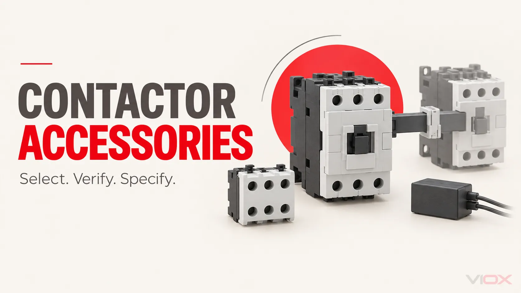
A contactor accessory is not interchangeable just because it performs the right function. Start with the exact contactor and coil designation. Count the control contacts you need, decide whether a paired mechanical interlock is required, and then select coil suppression for the actual control supply and switching device. Finally, verify that all selected accessories are approved to fit together on that contactor. The output should be a bill of materials (BOM) with manufacturer-supported part numbers, not a shopping list of generic accessory names.
| Control-panel requirement | Accessory to consider | Check before adding it to the BOM |
|---|---|---|
| Seal-in circuit, run indication, programmable logic controller (PLC) feedback, or electrical interlock | Built-in or add-on normally open (NO) / normally closed (NC) auxiliary contact | Contact count, control-circuit duty, exact mounting position, approved host models |
| Two contactors must not close at the same time, as in a reversing assembly | Matched mechanical interlock, plus the appropriate electrical cross-interlock | Approved contactor pair, physical arrangement, mounting clearance, control logic |
| A switched coil creates unacceptable voltage transients at a relay or electronic output | Manufacturer-approved coil suppressor | AC/DC coil type, voltage and frequency, suppression method, polarity, release-time effect, physical fit |
Selection rule: If the exact contactor model, coil code, or accessory compatibility document is missing, leave the accessory part number unconfirmed. A nominally similar part from another series is not an approved substitute.
1. Freeze the host contactor before selecting add-ons
Record the full catalog number, frame or series, main-pole arrangement, coil voltage, AC frequency or DC designation, and any built-in auxiliary contacts. Also record the control-output device, enclosure layout, and whether a second contactor will be mechanically paired.
These inputs matter because accessories are not standardized plug-ins across every contactor. A front auxiliary block can occupy space needed by another module; a side-mounted interlock can change the required spacing; a suppressor may clip to a coil housing or connect through a series-specific interface. Check the current accessory fitting diagram for the exact host model and revision, not only the broad product-family name.
The VIOX AC contactor range is a starting point for identifying the host family. Its published summaries explicitly say accessory availability and arrangements vary by series. Some individual VIOX model pages identify built-in auxiliary-contact arrangements, but the public pages reviewed for this guide do not establish a complete auxiliary-block, interlock, and suppressor compatibility table. Request that table before placing the final order.
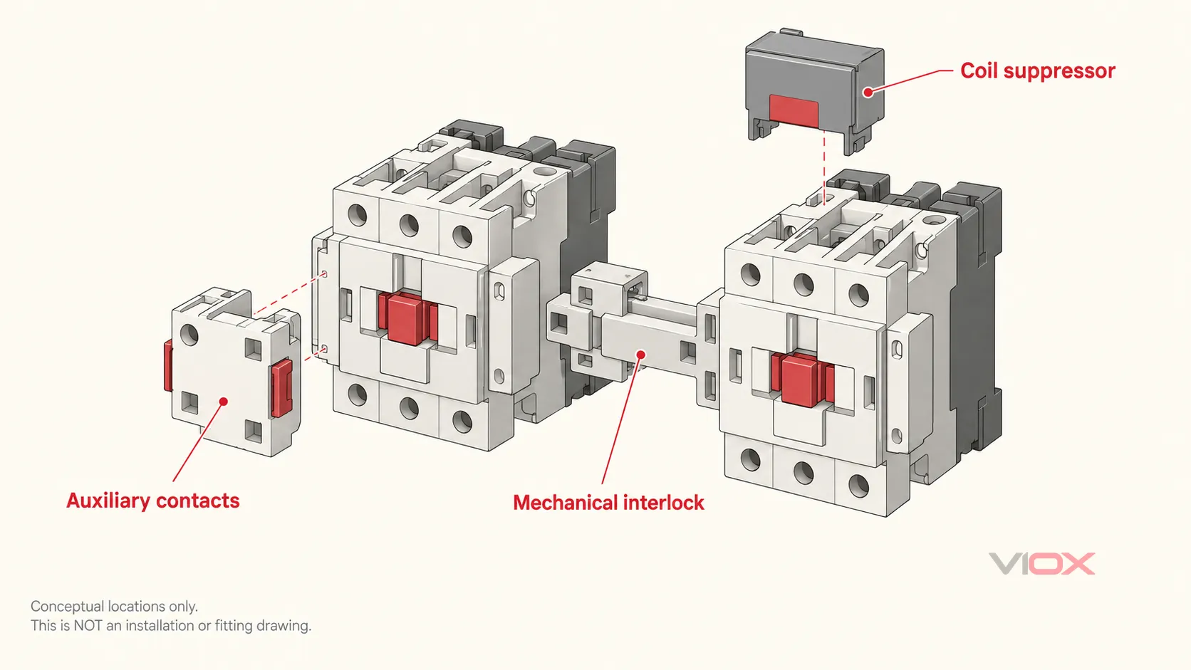
Conceptual location map, not a VIOX model-specific fitting drawing. Confirm the actual accessory locations and allowed combinations in the selected contactor’s documentation.
2. Count auxiliary contacts by function, not by habit
First list every control function that needs a contact. Then subtract contacts already built into the selected contactor only if their form and rating suit the circuit. A contact used in a seal-in path cannot also be assumed available for independent PLC feedback unless the approved schematic intentionally shares that point.
| Function | Typical contact request | Rating question |
|---|---|---|
| Three-wire seal-in or run indication | NO | What coil or indicator load does the contact actually switch? |
| Electrical cross-interlock of an opposite contactor | NC on each contactor | Is the NC contact approved and correctly rated for the other coil circuit? |
| PLC status input | NO or NC, according to logic | Will the input wetting current and voltage suit the contact specification? |
| Fault or permissive signal | NO or NC, according to fail-state design | Is the required signal a contactor-position indication or a separately verified protection signal? |
For each circuit, check rated operational voltage and the applicable control-circuit utilization category, such as AC-15 or DC-13 where specified. Do not copy the main poles’ motor-current rating into the auxiliary-contact row. Also distinguish an auxiliary contact block mounted on a contactor from a contactor relay, which is a separate coil-operated device. VIOX covers that distinction in Auxiliary Contact vs Main Contact.
An ordinary status contact follows the contactor mechanism; it is not automatically a safety-rated proof that every main pole is open. If a safety function calls for a mirror or mechanically linked contact, verify the applicable marked feature and the complete safety design rather than inferring it from an NC label.
3. Specify the mechanical interlock as a matched pair assembly
Two commands can overlap because of a control fault, contact bounce, or operating sequence. In a forward/reverse arrangement, simultaneous closure can create a serious fault. An electrical interlock uses an NC auxiliary contact in the other coil’s control path. A mechanical interlock physically prevents the paired contactors from closing together. They address different failure paths; use both where the engineered reversing scheme requires both.
Do not buy the interlock based only on the two contactors’ nominal ampere ratings. Confirm the maker’s approved pair of model numbers, frame combination, mounting orientation, rail or base arrangement, required spacing, and whether the interlock conflicts with side auxiliaries or a suppressor. Also verify any additional power-wiring kit separately; an interlock does not itself create a complete reversing starter.
Mechanical blocking does not replace motor overload protection, short-circuit protection, or a validated safety function. For the control-circuit sequence, see How to Wire a Contactor; use the actual manufacturer’s drawing for the final assembly.
4. Match the suppressor to the coil and control output
Switching an inductive contactor coil can generate a transient at the device that opens the coil circuit. Whether suppression is needed, and which type to use, depends on the coil, the PLC or relay output, the acceptable release time, and the accessory options approved for that contactor.
For a DC coil, a diode-based module may reduce the opening transient but can slow coil-current decay and contactor release. Check module polarity and timing implications. Other manufacturer-approved DC suppression approaches can trade a higher clamp voltage for faster release. For an AC coil, a rated resistor-capacitor (RC) module, varistor, or another approved module may be available. Do not assume one circuit type works on both AC and DC, and do not add a generic suppressor solely because its nominal voltage matches the control supply.
The BOM must identify coil designation, supply voltage and frequency where relevant, output device, chosen suppression module, location, and any release-time constraint. The detailed circuit trade-offs belong in VIOX’s contactor surge-suppressor guide; this page is about ordering the correct accessory as part of a complete assembly.
5. Verify coexistence, not just individual compatibility
An accessory can fit a contactor by itself yet conflict with another accessory in the same build. Before releasing the BOM, request a model-specific fitting drawing or accessory combination table and check:
- How many front and side positions are available, and whether there is an approved stacking order.
- Whether the interlock occupies a side position or changes the pair’s spacing.
- Whether the suppressor’s physical interface remains accessible after mounting auxiliaries and wiring.
- Whether terminal covers, wire bends, ventilation, and enclosure door clearance still work.
- Whether the exact auxiliary contact’s rated control duty and the coil module’s rated supply match the drawing.
- Whether the assembly needs market-specific approvals or documentation; never transfer a certificate from the host contactor to an unverified accessory combination.
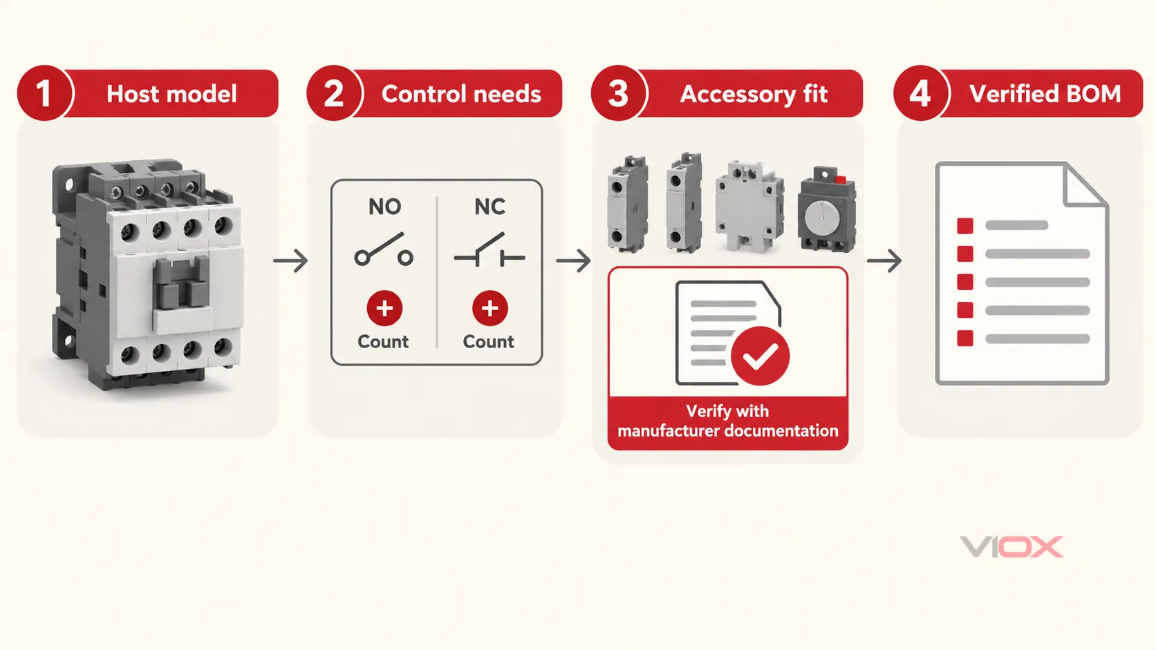
Use the exact host model and current manufacturer fitting document at the compatibility gate; the diagram is a selection workflow, not a wiring schematic.
Example: two-contactor reversing panel
Suppose a panel uses one forward and one reverse contactor. The design calls for one NO run-status contact and one NC cross-interlock contact on each contactor, plus a mechanical interlock across the pair. The coil-control outputs also require transient suppression. The preliminary count is therefore two contactors, four required contact functions, one matched mechanical-interlock assembly, and two coil suppression positions. The number of add-on auxiliary blocks may be zero, one, or more, depending on the contacts built into each exact contactor and how the approved blocks are configured. The suppressors’ part numbers cannot be fixed until the coil designations, output devices, fitting rules, and release-time limits are known.
That count is an accessory-planning example, not a complete motor starter, wiring diagram, or safety validation.
Copyable accessory BOM and supplier-verification sheet
Use one row per purchasable item. Change Unconfirmed to Verified only when a current manufacturer document explicitly covers the exact host model and accessory combination.
| BOM line | Quantity / required function | Exact host or pair | Electrical rating or supply to verify | Mounting / coexistence check | Manufacturer accessory part number | Evidence status and document |
|---|---|---|---|---|---|---|
| Contactor A | 1 / host | Full catalog number and coil code | Load duty and coil supply | Panel location | Record exact part number | Verified product sheet: ____ |
| Contactor B, if paired | 1 / host | Full catalog number and coil code | Load duty and coil supply | Paired arrangement | Record exact part number | Verified product sheet: ____ |
| Auxiliary block A | Required NO/NC count minus approved built-ins | Contactor A | AC-15/DC-13 or actual circuit duty | Front/side position, stacking | Unconfirmed: ____ | Fitting/rating page: ____ |
| Auxiliary block B, if paired | Required NO/NC count minus approved built-ins | Contactor B | Actual circuit duty | Front/side position, stacking | Unconfirmed: ____ | Fitting/rating page: ____ |
| Mechanical interlock, if needed | 1 matched assembly | Both exact contactor numbers | Function and approved pair | Pair orientation, spacing, side-module conflict | Unconfirmed: ____ | Pair-compatibility drawing: ____ |
| Coil suppressor A | 1 if required | Contactor A coil code | AC/DC, voltage, frequency, polarity if applicable | Mounting interface and release-time check | Unconfirmed: ____ | Module datasheet: ____ |
| Coil suppressor B, if paired | 1 if required | Contactor B coil code | AC/DC, voltage, frequency, polarity if applicable | Mounting interface and release-time check | Unconfirmed: ____ | Module datasheet: ____ |
Send this sheet with the control schematic, exact contactor model and coil code, enclosure constraints, destination market, and required quantity. Ask the supplier to return compatible part numbers plus the fitting and rating documents for the assembled combination. To check VIOX availability, contact [email protected]; do not substitute a general contactor product page for the assembly-level confirmation.
Standards and source boundary
IEC 60947-4-1:2023, corrected in 2026, covers electromechanical contactors, motor starters, and specified dedicated accessories within its stated scope. IEC 60947-5-1:2024 covers electromechanical control-circuit devices and switching elements used for control, signalling, and interlocking. Neither standard’s scope page is a substitute for a model-specific accessory compatibility list, installation drawing, or proof that a particular VIOX combination is certified.