On this page
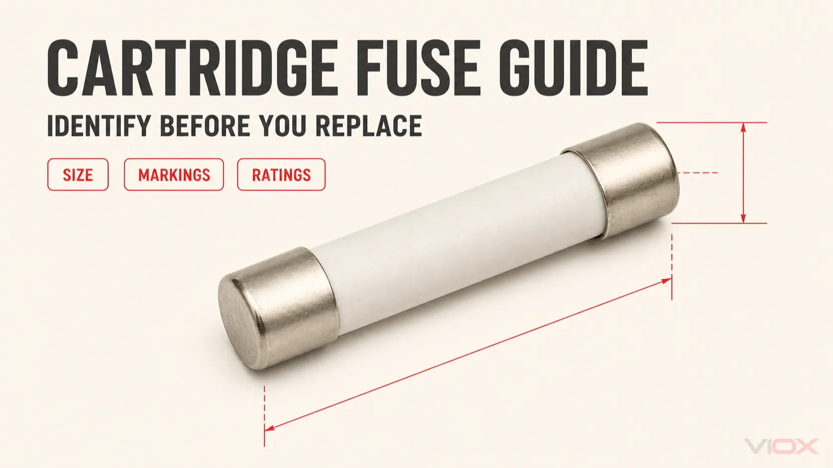
A cartridge fuse is a replaceable fuse-link with an enclosed body and conductive end contacts. However, cartridge fuse describes a construction family, not one universal rating system. A safe replacement must match the fuse system or series, physical dimensions, current rating, voltage and AC/DC duty, operating characteristic, breaking capacity, compatible holder, and required approval evidence. Matching only the size and ampere marking is not enough.
Use the original equipment documentation and the exact fuse datasheet whenever they are available. If the fuse is unmarked, heat-damaged, modified, or installed in equipment with an unknown fault level, stop and identify the circuit requirements before energizing a replacement.
| Replacement field | What must match or be verified | Why physical fit is insufficient |
|---|---|---|
| Fuse system or manufacturer series | IEC miniature, IEC industrial cylindrical, midget/supplementary, Class CC, or another defined system | Similar cylindrical bodies can have different rejection features and application rules |
| Dimensions and contacts | Body diameter, body length, cap dimensions, leads or tags | Nominal dimensions do not show all tolerances or contact geometry |
| Rated current | Original specification and protected circuit requirements | A higher current can defeat protection; a lower current can nuisance-open |
| Rated voltage and AC/DC duty | Equal to or above the maximum applicable circuit voltage, for the stated current type | Safe interruption depends on voltage and arc-extinction capability |
| Operating characteristic | Exact curve, IEC speed symbol, UL time-delay/non-time-delay type, or IEC utilization category | Two fuses with the same current can operate at very different times |
| Breaking capacity | At least the prospective fault current under the applicable conditions | An underrated fuse can rupture instead of clearing safely |
| Holder compatibility | Accepted fuse designation, power dissipation, contacts and terminal conditions | The holder is part of the thermal and mechanical current path |
| Approval and equipment evidence | Required IEC, UL/CSA, equipment listing or manufacturer instruction | Similar products may not preserve the original equipment evaluation |
What Is a Cartridge Fuse?
In the narrowest equipment context, a cartridge fuse is a tube-shaped fuse-link with metal end caps. The body may be glass, ceramic or another insulating material, and it may be empty, contain an arc-quenching filler, or incorporate internal structures for a specific operating characteristic. It is installed in clips, a fuse holder, a fuse block, a fuse drawer, or an approved switch-fuse assembly.
The term becomes broader in industrial and North American usage. Some standards families describe ferrule-ended, rejection-style or larger branch-circuit fuses as cartridge fuses even when their construction and permitted application differ substantially. Therefore, the word cartridge should never be treated as a complete specification.
The fuse-link is the part that melts and interrupts the overcurrent. The holder supports and connects it. See Fuse vs Fuse Link for the terminology boundary.
Cartridge Fuse Types by System and Application
Cartridge fuses are often grouped incorrectly because several classification axes are mixed together. Glass versus ceramic describes body construction. Fast versus time-delay describes operating behavior. Miniature, IEC cylindrical and Class CC identify different standards or application systems. One fuse can belong to several of these groups at the same time.
| Cartridge fuse family | Typical physical form | Common context | Main identification check |
|---|---|---|---|
| Miniature cartridge fuse | Small glass or ceramic tube with end caps, commonly 5 x 20 mm or 6.3 x 32 mm | Appliances, instruments, electronic equipment, power supplies and control circuits | Exact series, dimensions, speed symbol, voltage, breaking capacity and holder |
| IEC industrial cylindrical fuse-link | Ceramic body with cylindrical contact caps, including families such as 8 x 32, 10 x 38, 14 x 51 and 22 x 58 mm | Industrial panels, control circuits, distribution, motors, photovoltaic circuits and other IEC applications | IEC utilization category, AC/DC rating, dimensions, breaking capacity and compatible base or holder |
| North American midget or supplemental fuse | Ferrule-ended cartridge, often around 13/32 x 1-1/2 in | Control circuits and supplemental protection where permitted | Exact product category, voltage, interrupting rating and listed holder |
| Class CC fuse | Branch-circuit cartridge fuse with a rejection feature for a compatible Class CC holder | North American industrial control and branch-circuit applications | Class CC marking, rejection-style holder, voltage, current, time-delay status and interrupting rating |
| Axial-lead cartridge fuse | Cartridge body with a lead attached to each end | Printed circuit boards and wired electronic assemblies | Fuse series, lead form, soldering process, spacing and electrical ratings |
| High-breaking-capacity or filled cartridge fuse | Usually ceramic with filler and an internal element designed for higher fault interruption | Equipment and industrial circuits with greater prospective fault current | Model-specific breaking capacity at the stated voltage, curve and test framework |
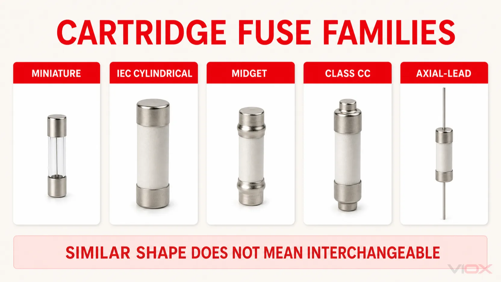
IEC 60127-1:2023 applies to miniature fuse-links for appliances, electronic equipment and component parts within its stated scope. It explicitly separates those products from fuses for low-voltage electrical installations covered by IEC 60269. IEC 60269-2 includes industrial systems with cylindrical contact caps as well as NH, bolted and other standardized systems.
The practical implication is simple: identify the standards system before using the size chart. Do not convert a miniature, IEC industrial or UL branch-circuit fuse into another family merely because the bodies look similar.
Cartridge Fuse Size Chart
The following dimensions are common nominal families, not universal equivalents. Manufacturer tolerances, cap shape, rejection features, lead forms and holder design still have to be checked on the exact outline drawing.
| Nominal size | Common family or context | Typical installation format | Replacement warning |
|---|---|---|---|
| 5 x 20 mm | IEC-oriented miniature cartridge family | PCB clips, equipment holder, rear or front panel holder | Check FF/F/M/T/TT characteristic, voltage and breaking-capacity code; glass and ceramic are not automatically interchangeable |
| 6.3 x 32 mm | Miniature equipment cartridge; approximately 1/4 x 1-1/4 in in relevant families | Equipment holder, fuse block or clips | Verify the exact 3AG/3AB or manufacturer series rather than converting from dimension alone |
| 8 x 32 mm | IEC industrial cylindrical family used by specified manufacturers and systems | Modular or compact industrial holder | Confirm the accepted fuse-link designation and holder documentation |
| 10 x 38 mm | IEC industrial cylindrical, PV, midget or other system-specific products | DIN-rail holder, fuse base or fuse module | The same nominal envelope can contain different categories, voltages and interruption capabilities |
| 14 x 51 mm | Larger IEC industrial cylindrical family | Industrial modular holder or switch-fuse equipment | Check holder power acceptance, utilization category and authorized servicing method |
| 22 x 58 mm | Larger IEC industrial cylindrical family | Industrial distribution holder or fuse switch-disconnector | Do not assume the holder is load-break capable unless that function is rated |
| 13/32 x 1-1/2 in | North American midget/supplementary and Class CC envelope | Class-specific or supplemental fuse block | Class CC uses rejection features and is not simply a generic 10 x 38 replacement |
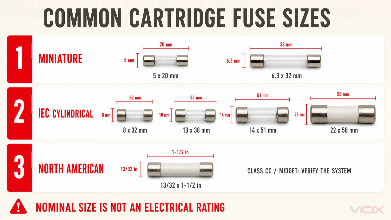
The Class CC distinction is especially important. Eaton documentation describes Class CC products and supplemental 10 x 38 or midget products separately, even though both are associated with a 13/32 x 1-1/2 in envelope. A Class CC rejection feature and compatible Class CC holder are intended to prevent insertion of a lesser-rated supplemental fuse. Defeating that feature or selecting by ruler measurement can change the protection system.
NH fuse-links use blade contacts and NH size designations rather than the diameter-by-length format in this table. Their selection belongs in NH Fuse vs Cylindrical Fuse, not in a cartridge size substitution chart.
Glass vs Ceramic Cartridge Fuses
Glass and ceramic are body materials, not complete performance ratings.
Glass cartridge fuse
A transparent glass body allows visual inspection of the element, although visual appearance alone cannot always confirm continuity. Glass miniature fuses are common in electronic equipment and lower-energy applications. Their breaking capacity varies by fuse series and must be read from the marking or datasheet.
Ceramic cartridge fuse
A ceramic body is opaque and is commonly used where greater thermal containment or a filled, higher-breaking-capacity design is required. However, ceramic does not automatically mean high breaking capacity, and glass does not automatically mean low breaking capacity. The model-specific rating remains decisive.
Replacing glass with ceramic, or ceramic with glass, is acceptable only when the equipment manufacturer or a complete specification comparison confirms the same dimensions, current, voltage, operating characteristic, breaking capacity, holder compatibility and required approvals. The construction difference is explained further in Glass Fuse vs Ceramic Fuse.
How to Read Cartridge Fuse Markings
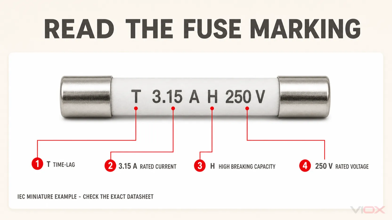
Marking systems depend on the standard and manufacturer. A common IEC miniature marking may look like:
T 3.15 A H 250 V
In that example:
Tidentifies a time-lag characteristic;3.15 Ais the rated current;Hidentifies a high breaking-capacity category within the applicable miniature-fuse marking system;250 Vis the rated voltage.
This example is not a universal decoding template for every industrial or UL fuse. Always confirm the product series and datasheet.
Miniature fuse speed symbols
Common IEC-oriented relative pre-arcing symbols include:
| Symbol | General meaning | Selection implication |
|---|---|---|
| FF | Very quick-acting | Very limited tolerance for temporary overcurrent; use the exact curve |
| F | Quick-acting | Used where significant startup inrush is not expected |
| M | Medium time-lag | Provides defined tolerance for moderate transient current |
| T | Time-lag | Common where transformer, motor or power-supply inrush must be tolerated |
| TT | Long or super time-lag | Intended for longer inrush profiles under the exact series data |
These symbols describe relative behavior within the applicable fuse framework. They do not provide one fixed opening time. Use the time-current curve at the relevant multiple of rated current.
Breaking-capacity letters on miniature fuses
For specified IEC miniature marking systems, L, H and E may identify low, high and enhanced breaking-capacity categories. Do not extend those letters to unrelated industrial fuse systems. An industrial cylindrical fuse may instead show an IEC utilization category such as gG, aM, aR or gPV, plus its current and voltage ratings.
Approval marks and series codes
Approval marks show that a defined product was evaluated within a particular certification framework. They do not make two differently evaluated fuses interchangeable. Record the manufacturer, complete series or part number, and approval reference where the equipment documentation requires them.
Cartridge Fuse Ratings Explained
Rated current
Rated current is established under defined conditions. It is not a promise that the fuse will carry that current indefinitely in every enclosure, holder and ambient temperature. Contact resistance, holder power acceptance, neighboring heat sources and the fuse’s own power dissipation affect operating temperature.
Do not increase the ampere rating to stop repeated fuse operation. Diagnose overload, inrush, ambient temperature, loose contacts and equipment faults first. The broad load-to-fuse selection process remains on the Electrical Fuse Types and Selection Guide.
Rated voltage and AC/DC duty
The voltage rating is the maximum stated circuit voltage at which the fuse is intended to interrupt under its specified conditions. It must be equal to or greater than the applicable circuit voltage. Confirm whether the marking applies to AC, DC or both.
A fuse can melt but fail to clear safely if its voltage or DC interruption capability is inadequate. Battery, photovoltaic and DC power-supply circuits can deliver substantial fault current even when their nominal voltage appears modest.
Breaking capacity or interrupting rating
Breaking capacity is the prospective current that the fuse can safely interrupt at a stated voltage and under specified test conditions. It must not be inferred from body material, dimensions or ampere rating.
The engineering check is:
Fuse breaking capacity >= prospective short-circuit current at the installation point
If the available fault current is unknown, obtain it from the system study, source data or a qualified calculation before selecting a replacement in a high-energy circuit.
Time-current curve and I^2t
The time-current curve shows how operating time changes as current increases. For inrush or pulse loads, compare the real waveform with the manufacturer’s curve and pulse guidance. I^2t data may be needed when coordinating with semiconductors or assessing let-through energy, but values must be compared under compatible conditions.
Utilization category
IEC industrial cylindrical fuses may use categories such as gG, aM, aR or gPV. These identify the intended protection function and current range, not merely speed. For example, an aM fuse does not provide complete motor overload protection by itself. Use the IEC 60269 Fuse Guide for that standards-focused decision.
How to Replace a Cartridge Fuse Safely
Cartridge-fuse replacement should be treated as restoration of an engineered protection function, not as inserting any conductive part that fits.
1. Identify why the fuse operated
Do not replace repeatedly without diagnosing the cause. Check for overload, short circuit, failed equipment, damaged wiring, excessive inrush, high enclosure temperature and overheated holder contacts. A fuse that keeps opening is a symptom, not the root cause.
2. De-energize and verify the equipment state
Follow the equipment manufacturer’s procedure and the applicable safe-work rules. Isolate every relevant energy source, verify absence of voltage with suitable equipment, and account for stored energy. Cartridge holders and pull-out carriers are not automatically load-break devices.
3. Record the complete original specification
Photograph and transcribe the markings before disposal. Record the manufacturer, series, dimensions, current, voltage, AC/DC duty, characteristic or utilization category, breaking capacity, approvals and any lead or striker arrangement.
4. Inspect the holder and surrounding circuit
Look for discoloration, melted insulation, loose clips, reduced spring pressure, corrosion, cracked carriers and damaged terminals. A new fuse cannot repair a high-resistance holder. Replace heat-damaged parts with approved components and investigate the cause of overheating.
5. Verify the replacement datasheet field by field
Use the replacement table at the beginning of this guide. Do not rely on online marketplace photographs or a seller’s claim that a product is equivalent. If the original series is obsolete, obtain a documented cross-reference from the equipment or fuse manufacturer.
6. Install without modifying the fuse or holder
Do not file caps, bend clips, add spacers, bypass rejection features, wrap the fuse in foil, or install a higher current rating. Follow the holder instructions for orientation, carrier engagement, conductor termination and enclosure closure.
7. Re-energize only after the fault and protection path are verified
Use the equipment’s approved commissioning procedure. If the replacement opens again, isolate the equipment and continue diagnosis. Never keep increasing the fuse rating.
Matching the Cartridge Fuse to Its Holder
The holder contributes contact resistance, terminal heating, insulation, spacing and touch protection. Match the exact accepted fuse format, holder voltage and current ratings, permitted fuse power dissipation, conductor range, environmental condition and fault-duty documentation.
A 10 x 38 holder is not automatically approved for every 10 x 38 fuse. PV, supplemental, IEC industrial and Class CC products can require different holders and evidence. Use the Fuse Holder Types and Selection Guide for the holder decision.
If the device must be operated under load or provide a defined isolation function, specify an appropriately rated fuse switch-disconnector. A carrier that can be opened does not prove load-break capability. See Fuse Holder vs Fuse Switch Disconnector.
Cartridge Fuse Replacement Checklist
Before approving a substitute, the specification should answer all of the following:
- What is the exact fuse standard, class, category or manufacturer series?
- What are the body and contact dimensions, including rejection features?
- What is the rated current?
- What is the maximum circuit voltage, and is the duty AC, DC or both?
- What operating characteristic or utilization category is required?
- What breaking capacity is required at that voltage?
- Are time-current and I^2t data compatible with the protected equipment?
- Is the fuse accepted by the installed holder?
- Are ambient temperature, enclosure heating and fuse power dissipation acceptable?
- Which approval or equipment evidence must be preserved?
VIOX supplies cylindrical fuse-links and related low-voltage fuses and fuse holders for industrial panels, OEM equipment and photovoltaic applications. For model-level selection, provide the complete checklist rather than only the required ampere rating.
Frequently Asked Questions
Can I replace a cartridge fuse with another fuse of the same size and amperage?
Not without additional checks. Match voltage and AC/DC duty, operating characteristic, breaking capacity, fuse system or class, holder compatibility and required approvals. The same size and ampere marking can conceal materially different interruption performance.
Can a ceramic cartridge fuse replace a glass fuse?
Only when the equipment manufacturer or a complete datasheet comparison confirms compatibility. Ceramic construction alone does not establish the same speed, breaking capacity, voltage, dimensions or approvals.
Are 10 x 38 mm fuses and Class CC fuses interchangeable?
No general interchangeability should be assumed. Class CC is a defined branch-circuit fuse system with a rejection feature and compatible holder. IEC 10 x 38, midget and supplemental products can share a similar nominal envelope while having different application rules and ratings.
Can I test a cartridge fuse with a multimeter?
After safe isolation and removal according to the equipment procedure, a continuity or resistance test can confirm whether the fuse element is open. It cannot prove that the fuse has the correct voltage, breaking capacity, operating curve, calibration or remaining service integrity. Replace questionable or damaged fuses with the exact approved type.
Is a fuse holder the same as a disconnect switch?
No. A basic fuse holder provides support and electrical contacts. It is not automatically rated to make or break load current or to serve as an isolation device.
Technical Sources
- IEC 60127-1:2023, Miniature fuses, definitions and general requirements
- IEC 60269-1:2024, Low-voltage fuses, general requirements
- IEC 60269-2:2013 with AMD1:2016 and AMD2:2024, standardized industrial fuse systems
- UL Solutions, Fuse and Fuseholder Services, UL 248 and UL 4248 scopes
- Littelfuse, 5 x 20 mm IEC fuse cap marking guide
- SCHURTER, Fuse-link characteristics and marking
- Eaton, Class CC and supplemental 10 x 38 fuse-block distinction
The standards define product families and test frameworks, but safe application still depends on the exact fuse datasheet, holder documentation, protected equipment and installation rules.