

On this page
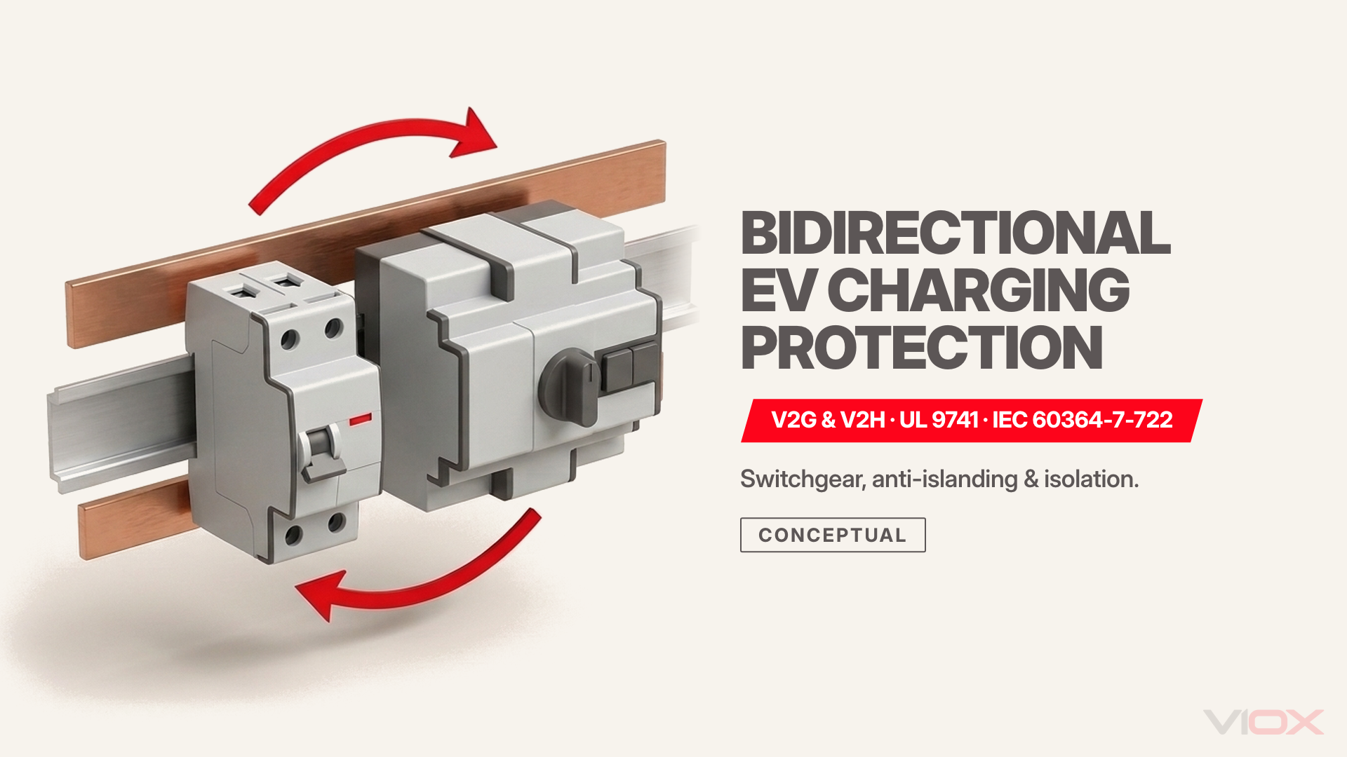
Bidirectional EV charging protection converts a unidirectional electric vehicle load circuit into an interactive distributed energy resource (DER) circuit that must interrupt fault currents, detect smooth DC earth leakage, and block unintentional islanding in both import and export directions. Unlike standard charging circuits, Vehicle-to-Grid (V2G) and Vehicle-to-Home (V2H) installations require bidirectional-rated overcurrent and residual-current devices, certified anti-islanding disconnection within 2 s under IEEE 1547, busbar backfeed verification under NEC 705.12 or IEC prosumer rules, and—for outage backup—a listed Microgrid Interconnection Device (MID) or Automatic Transfer Switch (ATS) with coordinated neutral-earth bonding.
Scope & Standards Baseline: This guide addresses low-voltage AC and DC electrical protection architecture for stationary bidirectional EV power export systems across both IEC/UK markets (IEC 60364-7-722:2018, IEC 61851-1, IEC 61851-23:2023, IEC 60364-8-82, and BS 7671:2018+A3:2024) and North American jurisdictions (UL 9741, UL 1741 SB/SC, IEEE 1547-2018, and NFPA 70 / NEC Articles 625.48, 702, and 705.12). Exact terminal ratings, breaking capacities, and vehicle-to-charger pairing approvals always remain governed by the listed equipment datasheet and local Authority Having Jurisdiction (AHJ).
Why Unidirectional EV Protection Fails Under Bidirectional Power Flow
Standard unidirectional EV charging protection assumes fault and load current always enter from the utility line terminals and exit toward the vehicle load. When an EV battery discharges 7.6 kW to 22 kW (or higher in DC systems) back into a distribution board, reversed energy flow defeats directional electronic trip units, polarized DC arc chutes, busbar thermal limits, and grid-isolation assumptions.
Treating a V2G or V2H circuit like a conventional unidirectional Mode 3 or Level 2 charger introduces five distinct failure modes across AC and DC protection zones:
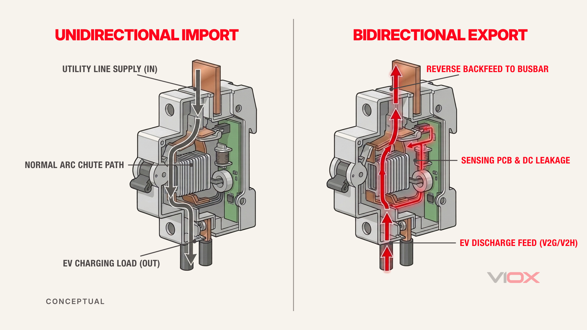
| Failure Mode | Unidirectional Device Assumption | What Fails During V2G / V2H Reverse Export | Engineering Consequence | Required Bidirectional Mitigation |
|---|---|---|---|---|
| Directional RCBO / RCCB electronic damage | Line terminals remain energized only on the supply side | Reverse power from the EV keeps internal electronic sensing energized after contacts open | Burned trip electronics, failed subsequent earth-fault clearing, non-compliance with BS 7671 Reg 530.3.201 | Install bidirectional-rated RCBOs/RCCBs marked for supply on either terminal set |
| Polarized DC MCB arc-chute failure | DC current flows only in the marked polarity direction | Reverse DC discharge forces the fault arc away from magnetic blowout coils and arc splitters | Sustained DC arc inside the enclosure, contact welding, thermal runaway | Specify non-polarized (bidirectional) DC MCBs or MCCBs rated for full system DC voltage |
| Smooth DC leakage blinding of Type A RCDs | Standard AC or pulsating DC residual current only | Inverter bridge faults during charging or discharging inject > 6 mA smooth DC leakage | Magnetic core saturation blinds upstream Type A RCDs to lethal 30 mA AC earth faults | Specify Type B RCD/RCBO (IEC 62423) or verified bidirectional-capable Type A + 6 mA RDC-DD |
| Unintentional islanding (utility backfeed) | Loss of utility automatically de-energizes premises wiring | EV inverter continues energizing a de-energized distribution feeder during a grid outage | Electrocution hazard to utility lineworkers and out-of-phase reclosing damage | Certified anti-islanding (< 2 s under IEEE 1547 / IEC 62116) plus physical MID/ATS isolation for V2H |
| Panel busbar thermal overload | Single supply enters at the main breaker only | Utility main supply and EV backfeed breaker feed shared busbars from opposite ends | Busbar carries combined current above continuous rating without tripping the main breaker | Enforce NEC 705.12 120% busbar rule, line-side supply tap, or IEC prosumer feeder derating |
Selection rule: Never reuse an existing unidirectional EV branch circuit for V2G or V2H export until every series-connected OCPD, RCD, DC isolator, and busbar rating is verified for reverse current and fault interruption. For unidirectional installations without power export, consult our commercial EV charging protection architecture guide or home EV charger installation requirements.
AC Bidirectional vs. DC Bidirectional Protection Architecture
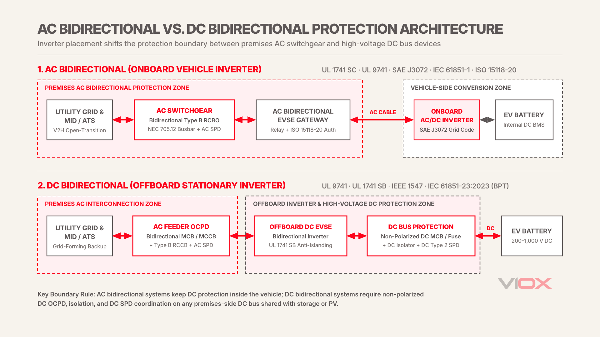
Bidirectional EV charging systems split into two distinct electrical architectures—AC Bidirectional (onboard vehicle inverter) and DC Bidirectional (offboard charger inverter)—which shift the boundary between vehicle-side protection and premises switchgear. Specifying external circuit breakers, RCDs, and surge devices without first locking the inverter location causes mismatched voltage ratings and redundant or missing DC fault clearing.
In an AC Bidirectional (V2G-AC) architecture, the bidirectional inverter sits inside the electric vehicle (governed in North America by SAE J3072). The wall-mounted bidirectional EVSE acts as a grid-supervisory relay, meter, and communication gateway (certified to UL 1741 Supplement SC alongside UL 9741) using ISO 15118-20 signaling to verify that the connected vehicle holds a compliant grid-interconnection profile before closing its main contactors. Premises switchgear therefore handles AC bidirectional current only, though earth-leakage protection must still account for DC fault propagation through the onboard inverter.
In a DC Bidirectional (V2G-DC / V2H-DC) architecture, the bidirectional AC/DC power conversion stage resides offboard inside the wallbox or cabinet (governed by UL 9741, UL 1741 SB, and IEC 61851-23:2023 Bidirectional Power Transfer). High-voltage DC (typically 200 V DC to 1,000 V DC) flows directly between the vehicle traction battery and the offboard inverter via the charging cable. Because the inverter is permanently installed on premises, external protection spans both a bidirectional AC grid-interconnection feeder and internal or external DC-bus overcurrent, isolation, and surge protection.
| Architecture Parameter | AC Bidirectional (Onboard Inverter) | DC Bidirectional (Offboard Inverter) |
|---|---|---|
| Primary inverter location | Inside the EV (onboard charger/inverter) | Stationary offboard bidirectional EVSE cabinet |
| North American equipment standards | UL 9741 + UL 1741 Supplement SC + SAE J3072 | UL 9741 + UL 1741 SB + IEEE 1547 / 1547.1 |
| IEC equipment standards | IEC 61851-1 + ISO 15118-20 + local grid code | IEC 61851-23:2023 (BPT) + IEC 62116 + ISO 15118-20 |
| Premises AC branch OCPD | Bidirectional-rated AC MCB / RCBO / MCCB | Bidirectional-rated AC MCB / MCCB sized for inverter export + import |
| Premises DC-side OCPD & isolation | Managed internally within the EV | Non-polarized DC MCB / fuse + DC load-break isolator + DC SPD (if external DC bus exists) |
| Residual current (earth leakage) | Bidirectional Type B RCBO/RCCB or verified Type A + 6 mA RDC-DD | Type B RCD/RCCB on AC feeder (required unless galvanic isolation is proven by transformer) |
| Typical residential / commercial power | 7.4 kW to 22 kW AC | 10 kW to 12 kW (residential V2H) up to 50 kW+ (commercial fleet V2G) |
| V2H outage-backup isolation | External MID or ATS required between utility and backed-up loads | Integrated or companion MID / ATS gateway isolating grid from backup panel |
Selection rule: Choose AC-side-only bidirectional premises switchgear when deploying SAE J3072 / UL 1741 SC onboard-inverter EVSEs; add non-polarized DC overcurrent, isolation, and DC Type 2 SPD coordination whenever an offboard DC bidirectional cabinet shares an external DC bus with stationary battery storage or solar PV. For detailed unidirectional DC fast charger fuse and surge coordination, see our DC fast charger overcurrent and overvoltage protection guide.
Anti-Islanding, V2H Transfer Switching, and Neutral-Earth Bonding
Grid-tied V2G export and outage-backup V2H operation impose opposite electrical states during a utility blackout: V2G must cease energizing the grid within 2 s under IEEE 1547 Clause 8 (and comparable IEC 62116 / national grid-code windows), whereas V2H must physically sever the utility connection via a listed MID or ATS before forming a local microgrid.
Attempting to run V2H backup without certified transfer switching creates two lethal hazards: backfeeding a de-energized utility transformer (stepping 230 V or 240 V up to medium voltage on downed lines) and losing a valid neutral-to-earth (N-PE) reference when the utility supply neutral is opened.
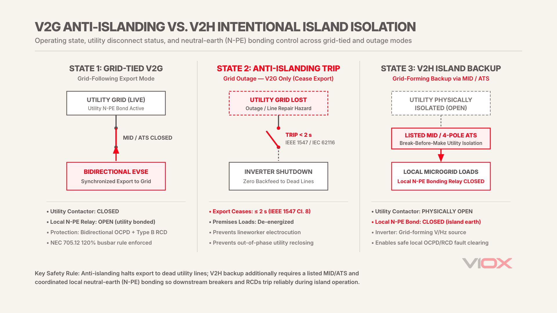
Grid-Tied V2G vs. Intentional Island V2H Operating States
| Operating Mode | Inverter Control State | Utility Grid Connection | Primary Protection Function | Neutral-Earth (N-PE) Bonding Requirement |
|---|---|---|---|---|
| Normal charging (Import) | Grid-following rectifier | Closed (Utility energized) | Bidirectional OCPD + Type B RCD / RDC-DD + AC SPD | Standard utility service N-PE bond active |
| Grid-tied V2G (Export) | Grid-following inverter synchronized to utility | Closed (Utility energized) | Active & passive anti-islanding (< 2 s trip) + voltage/frequency ride-through | Standard utility service N-PE bond active |
| Utility outage — V2G only | Immediate shutdown (cease to energize) | Open (Inverter contactors open) | Anti-islanding prevents energizing dead Area EPS | No local source energized; fault path inactive |
| Utility outage — V2H backup | Grid-forming voltage/frequency source | Physically isolated via listed MID or 4-pole/switched-neutral ATS | Open-transition isolation prevents grid backfeed; local OCPD/RCD clears island faults | Dedicated local N-PE bond must close during island mode (and open before grid reconnection) |
Selection rule: Use a grid-following UL 1741 / IEC 62116 anti-islanding EVSE alone only when zero outage-backup capability is required; add a listed MID or Automatic Transfer Switch with verified neutral-earth bonding coordination whenever the EV must energize home or facility loads during a blackout.
Transfer Switch Topology and Neutral-Earth Bonding Transfer
When a V2H system disconnects from the utility to supply a critical-loads subpanel or whole-home main panel, the transfer switch must provide a mechanically or electrically interlocked break-before-make (open transition) path unless the system is explicitly engineered for synchronized closed transition.
In IEC TN-S and TT installations—and in North American separately derived standby systems under NEC Article 702—opening all live conductors including the neutral removes the utility transformer’s earth reference. Without a local earthing electrode and an automatic N-PE bonding relay inside the V2H inverter or ATS assembly, an earth fault during V2H island mode will not generate sufficient fault current to trip downstream MCBs or RCDs. For step-by-step wiring logic on grid, inverter, and neutral-bonding transfer, reference our automatic transfer switch wiring guide for solar and inverter systems.
Busbar Backfeed Capacity and the NEC 705.12 120% Rule
When a bidirectional EV charger backfeeds power into an existing load center through a load-side circuit breaker, NEC 705.12 treats the EVSE as an interconnected electric power production source whose continuous export current must be added to any existing solar PV or battery storage backfeed against the panel busbar limit.
Under NEC 705.12 (705.12(B)(3)(2) in NEC 2020; 705.12(B)(2) in NEC 2023)—widely known as the 120% busbar rule—the sum of the main overcurrent device rating and 125% of all backfed power-source inverter output currents must not exceed 120% of the busbar ampacity, provided the backfeed breaker sits at the opposite end of the busbar from the main breaker:
Maximum Combined Backfeed Breaker Rating = (Busbar Ampacity × 1.20) − Main Circuit Breaker Rating
Worked Calculation: 200 A Panel with Existing Solar PV Adding V2H
Consider a common North American residential service panel rated with a 200 A busbar and a 200 A main circuit breaker that already hosts a 7.6 kW solar PV inverter (32 A continuous output, protected by a 40 A backfeed breaker):
- Calculate total 120% busbar ceiling: 200 A × 1.20 = 240 A.
- Subtract the main breaker rating: 240 A − 200 A = 40 A maximum total backfeed breaker allowance.
- Account for existing solar PV: The 40 A solar backfeed breaker consumes 100% of the 40 A allowance (40 A − 40 A = 0 A remaining).
- Evaluate adding an 11.5 kW V2H bidirectional charger: At 240 V AC, 11.5 kW equals 48 A continuous export, requiring a 60 A backfeed breaker (48 A × 1.25 = 60 A). Placing that 60 A breaker on the existing 200 A busbar yields 200 A + 40 A + 60 A = 300 A, exceeding the 240 A limit by 60 A and failing NEC 705.12.
Compliant Engineering Mitigations When Busbar Allowance Is Exceeded
- Main breaker derating: Downsize the main breaker on a 200 A busbar from 200 A to 150 A (if NEC Article 220 load calculations permit), increasing backfeed allowance from 40 A to 90 A—still tight for 40 A solar + 60 A V2H (100 A total), unless export current is software-limited via a listed Power Control System (PCS).
- Supply-side (line-side) connection: Interconnect the V2H MID/gateway ahead of the main service panel under NEC 705.11, bypassing the main panel busbar backfeed limit entirely.
- Busbar upgrade or dedicated DER combiner panel: Upgrade to a 225 A busbar with a 200 A main breaker (yielding 70 A allowance) or route both PV and V2H into a listed generation combiner panel with an integrated PCS.
- IEC prosumer distribution check (IEC 60364-8-82): In IEC switchgear assemblies (IEC 61439), verify the rated diversity factor (RDF) and busbar thermal rating where the incomer current plus bidirectional EVSE export current can simultaneously feed downstream outgoing circuits on the same busbar section.
Always verify whether the chosen breaker itself is listed for reverse feed before terminating a backfeed circuit; see our guide on whether you can reverse feed a circuit breaker under NEC and IEC 60947-2.
Earth-Leakage (RCD), Overcurrent (OCPD), and Surge Protection Selection
Selecting protection devices for a bidirectional EV installation requires matching each electrical zone’s fault-current direction, leakage waveform, and transient exposure rather than copying a unidirectional bill of materials. Every series protective device between the utility meter and the bidirectional EVSE must carry explicit bidirectional or non-polarized ratings.
| Protection Zone | Recommended Device | Mandatory Bidirectional Requirement | Governing Standard | Key Selection Boundary |
|---|---|---|---|---|
| AC EVSE feeder — combined OCPD + RCD | Bidirectional Type B RCBO (30 mA) | Manufacturer-declared bidirectional terminals (no one-way Line/Load restriction) | IEC 61009-1:2024, IEC 62423, BS 7671 Reg 530.3.201 | Mandatory when charger lacks verified internal galvanic isolation or bidirectional 6 mA RDC-DD |
| AC EVSE feeder — separate OCPD + RCD | Bidirectional MCB/MCCB + Type B RCCB | Non-directional AC breaker + Type B RCCB rated for smooth DC and high-frequency leakage | IEC 60898-1 / IEC 60947-2, IEC 62423 | Verify upstream-to-downstream selectivity so a 30 mA branch fault does not trip the main incomer |
| DC bus (offboard DC bidirectional EVSE) | Non-polarized DC MCB / MCCB + gPV/aR fuse | Zero polarity sensitivity for bidirectional arc interruption | IEC 60947-2 / UL 489 (or UL 489B if PV-coupled) | Size rated operational voltage Ue ≥ maximum EV battery pack voltage (typically 1,000 V DC) |
| V2H outage isolation | Listed MID or Dual Power ATS | Mechanically interlocked open transition + auxiliary N-PE bonding control | UL 1008 / UL 1741 / IEC 60947-6-1 | Match short-time withstand current (Icw) or conditional short-circuit current with upstream OCPD |
| Transient overvoltage (AC & DC) | Type 1+2 AC SPD (main) + Type 2 AC/DC SPD (charger) | MCOV (Uc) above maximum grid + export voltage swing; DC SPD matched to pack voltage | IEC 61643-11 / UL 1449 | Keep total SPD lead length ≤ 0.5 m to limit let-through voltage at sensitive inverter IGBTs |
Selection rule: Specify a bidirectional Type B RCBO or Type B RCCB as the default earth-leakage barrier on AC bidirectional feeders unless the EVSE manufacturer provides written test documentation proving that an integrated IEC 62955 6 mA RDC-DD remains active during both charging and discharging states.
For deeper component-level verification—without duplicating those rules here—consult our dedicated guides on how to read bidirectional RCBO markings, polarized vs. non-polarized DC circuit breakers, and Type B vs. Type F vs. Type EV RCCB selection.
VIOX Component Supply Boundary for V2G and V2H Panels
VIOX manufactures low-voltage distribution and protection switchgear—not complete UL 9741 bidirectional EVSE stations or vehicle-specific MID gateways. For EPCs, panel builders, and electrical installers assembling the external distribution and backup panels around a certified bidirectional charger, VIOX supplies the panel-level protection devices matched to IEC 62423, IEC 61009-1, IEC 60947-6-1, and IEC 61643-11 frameworks, including VIOX VRL22B Type B RCBOs, VKL11B Type B RCCBs, VIOX Automatic Transfer Switches (ATS), DC MCBs, and Surge Protection Devices (SPD). Always confirm terminal directionality markings and project-specific regional certifications on the individual product datasheet prior to panel assembly.
Governing Standards Crosswalk: IEC, BS 7671, UL, IEEE, and NEC
Bidirectional EV charging sits at the intersection of EV conductive charging standards, distributed-generation grid codes, and fixed-installation wiring rules. Relying on an EV charger standard alone leaves grid-interconnection, busbar backfeed, and panel-level switchgear compliance uncovered.
| Compliance Domain | IEC / European & UK Standard | North American Standard | What the Standard Governs in V2G / V2H |
|---|---|---|---|
| EV power export & DC charger safety | IEC 61851-1 & IEC 61851-23:2023 (BPT) | UL 9741 / CSA C22.2 No. 348 | Electrical safety, isolation, and bidirectional power transfer control of offboard EVPE |
| Grid interconnection & smart inverter | IEC 62116 + national grid codes (e.g., EN 50549, G99) | UL 1741 SB / Supplement SC + IEEE 1547-2018 / 1547.1 | Anti-islanding (< 2 s), voltage/frequency ride-through, Volt-Var/Freq-Watt support |
| Onboard AC inverter authorization | ISO 15118-20 (BPT communication) | SAE J3072 + ISO 15118-20 | Vehicle-to-EVSE handshake verifying onboard inverter grid-code compliance |
| Premises wiring & backfeed rules | IEC 60364-7-722:2018 & IEC 60364-8-82 | NFPA 70 (NEC) Art. 625.48, 702, 705.12 | Dedicated EV feedback circuits, interactive listing, standby transfer, 120% busbar rule |
| Bidirectional switchgear & RCDs | IEC 61009-1:2024, IEC 62423, BS 7671+A3:2024 | UL 489 (backfeed-rated) + UL 2231 (CCID) | Bidirectional terminal ratings, Type B smooth DC detection, personnel shock protection |
Selection rule: Before submitting a V2G or V2H single-line diagram to a utility or AHJ, verify compliance across all five rows above—especially pairing the EVSE equipment listing (UL 9741 or IEC 61851-23) with the applicable grid-interconnection standard (UL 1741 / IEEE 1547 or EN 50549 / IEC 62116).
Pre-Commissioning Protection Checklist for V2G and V2H Installations
Commissioning a bidirectional EV charging installation requires verifying both import (charging) and export (discharging) fault paths before energizing the system. Skipping reverse-flow checks can leave an installation appearing normal during charging while failing catastrophically on the first outage or export cycle.
- Verify Equipment Listing & Pairing: Confirm the EVSE carries explicit bidirectional listing (UL 9741 + UL 1741 SB/SC or IEC 61851-23 BPT) and matches the vehicle communication profile (ISO 15118-20 / SAE J3072).
- Audit Every Series Device for Directionality: Inspect markings on the EV branch breaker, RCBO/RCCB, and any DC MCBs to confirm zero unidirectional Line/Load restrictions or polarized DC markings are violated.
- Validate Busbar Thermal & Backfeed Math: Document NEC 705.12 120% busbar compliance (including existing solar PV and stationary BESS) or IEC 61439/60364-8-82 rated diversity factor limits.
- Confirm Earth-Leakage Coverage in Export Mode: Verify Type B RCD/RCBO installation (or written proof that an integrated IEC 62955 6 mA RDC-DD remains active during reverse discharge) and test trip times on both AC and DC fault ramps.
- Test Anti-Islanding & V2H Transfer Isolation: Simulate utility loss under controlled load; verify grid-tied V2G ceases export within the local grid-code limit (< 2 s under IEEE 1547), and verify V2H MID/ATS opens utility poles cleanly before closing island backup power.
- Verify Island-Mode N-PE Bonding: Measure neutral-to-earth continuity and loop impedance in V2H island mode to confirm the local bonding relay closes during backup and opens upon grid restoration without creating a parallel neutral-earth loop.
- Apply Mandatory Dual-Supply Labeling: Affix permanent warning placards at the main service panel, distribution board, and meter base identifying the presence of a bidirectional EV power source and its isolating disconnect location.
If you are specifying Type B RCBOs/RCCBs, non-polarized DC breakers, ATS assemblies, or SPDs for an upcoming V2G or V2H distribution panel project, send your single-line diagram and regional standard requirements to [email protected] for component datasheets and rating verification.
Frequently Asked Questions
Can a standard Type A RCD with a 6 mA DC sensor protect a bidirectional V2G or V2H circuit?
Only if the specific Type A RCD/RCBO is manufacturer-rated as bidirectional and the integrated IEC 62955 6 mA RDC-DD is explicitly verified by the EVSE manufacturer to detect smooth DC leakage during reverse power export as well as charging. Because many standard IEC 62955 modules and electronic Type A RCBOs are evaluated only for unidirectional Mode 3 charging, a bidirectional Type B RCCB or RCBO (IEC 62423) is the safer default when export-mode documentation is absent.
Does V2H home backup require both anti-islanding protection and an automatic transfer switch?
Yes. Anti-islanding protection (IEEE 1547 / UL 1741 / IEC 62116) detects grid loss and halts utility export, while a listed Microgrid Interconnection Device (MID) or Automatic Transfer Switch (ATS) physically isolates premises wiring before the V2H inverter forms a local backup island. Anti-islanding without an MID/ATS simply shuts the system down during a blackout, whereas an ATS without interconnection protection cannot safely parallel with the grid.
Why do DC bidirectional chargers need non-polarized DC breakers on the DC bus?
Polarized DC circuit breakers rely on permanent magnets oriented for a single current direction to push the breaking arc upward into the arc-quenching splitter plates. During V2G or V2H discharge, DC current reverses direction; a reversed fault current deflects the arc away from the arc chute toward the housing, causing sustained arcing, contact welding, and potential fire. Non-polarized DC MCBs and MCCBs extinguish arcs identically in both import and export directions.
Sources
- IEC 60364-7-722:2018 — Low-voltage electrical installations: Supplies for electric vehicles (including EV feedback circuits)
- IEC 61851-1:2017 — Electric vehicle conductive charging system: General requirements
- IEC 62955:2018 — Residual direct current detecting device (RDC-DD) for Mode 3 EV charging
- IEC 62423:2009 — Type F and Type B residual current operated circuit-breakers
- IEC 61009-1:2024 — Residual current operated circuit-breakers with integral overcurrent protection (RCBOs)
- IET BS 7671:2018+A3:2024 — Requirements for Electrical Installations (Amendment 3: Bidirectional Protective Devices)
- NFPA 70 — National Electrical Code (NEC Articles 625.48, 702, and 705.12)