On this page
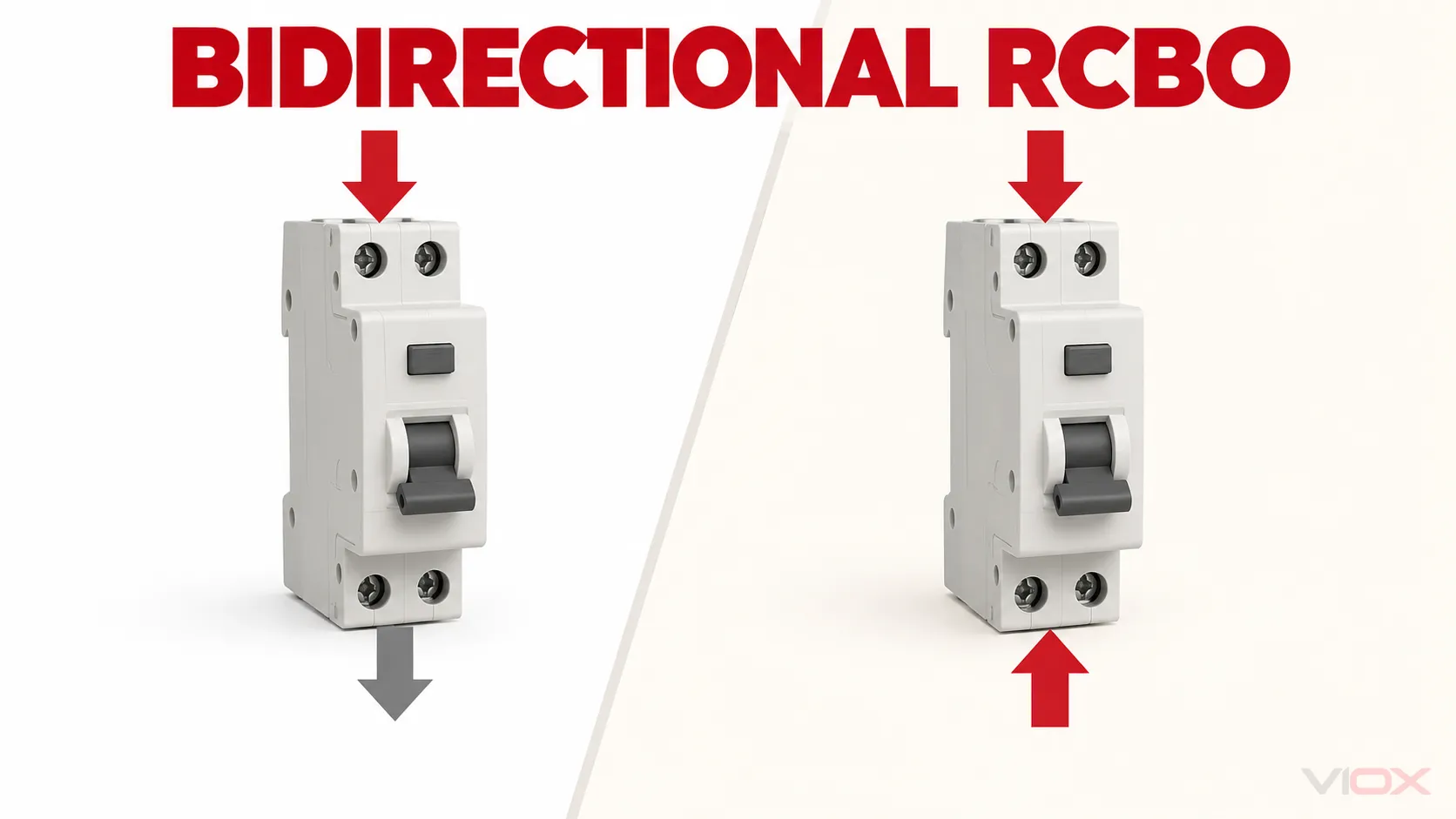
A bidirectional RCBO is a Residual Current operated Circuit-Breaker with integral Overcurrent protection whose manufacturer intends a source of supply to be connected to either or both sets of connection terminals. A unidirectional RCBO, by contrast, is intended to receive the source only at one defined terminal set.
The selection question is therefore not simply, “Can current flow both ways?” Alternating current already reverses direction every cycle, and net power can reverse in a building without making every final-circuit RCBO bidirectional. The decisive question is:
Could the intended circuit place a source of supply at either terminal set of this RCBO in any normal, alternate-source, test, isolation, or fault state—and does the exact model documentation permit that condition?
If the answer may be yes, use a device with an explicit manufacturer declaration suitable for that source arrangement. Do not infer suitability from appearance, DIN-rail fit, another model in the same range, or the absence of a visible arrow.
Safety boundary: Source mapping, protective-device selection, connection, inspection, and testing must be completed by competent persons under the rules applicable to the installation. This article is a specification guide, not a wiring procedure.
Key Selection Points
- Bidirectional is about permitted source connection, not just the direction of load current.
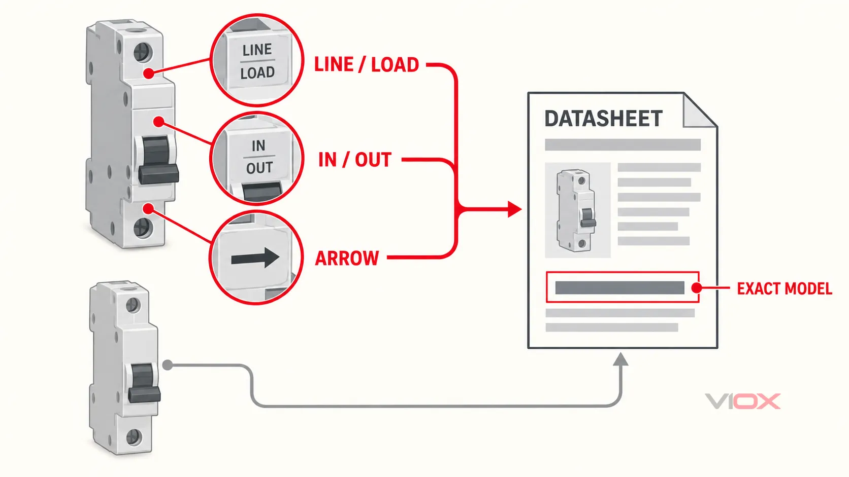
- Line/Load, In/Out, or directional-arrow markings indicate that terminal orientation matters.
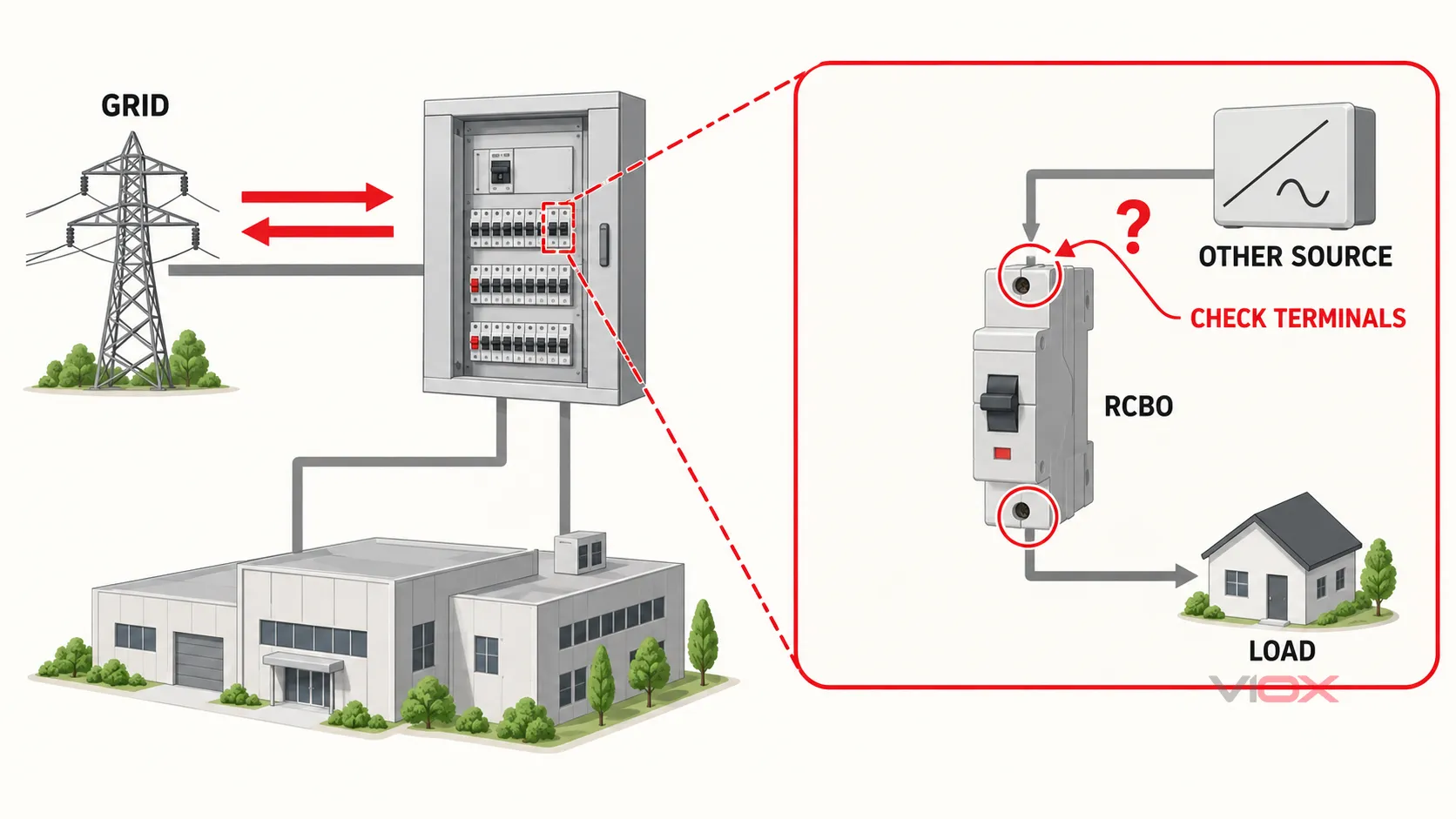
- Solar, storage, or EV equipment does not automatically make every RCBO in the board bidirectional. Check the actual source path through each device.
- Directionality is only one requirement. Residual-current type, sensitivity, poles, neutral switching, curve, breaking capacity, voltage dependence, and assembly compatibility remain separate decisions.
- Approve the exact catalog number. A declaration for one RCBO does not automatically apply to an older version or adjacent model.
Four Concepts That Must Not Be Confused
Many weak explanations combine four different ideas:
| Concept | What it means | What it does not prove |
|---|---|---|
| AC current direction | Instantaneous current reverses with the AC waveform | That either terminal set may be used as the source connection |
| Net power-flow direction | The installation imports or exports energy over time | That every protective device on every circuit needs bidirectional construction |
| Source position at the RCBO | A supply can energize one terminal set, the other terminal set, or both under different states | That the selected RCBO is suitable for those states |
| Manufacturer declaration | The exact model is intended for the stated source-terminal arrangement | That all other RCBO ratings and installation requirements are satisfied |
This distinction matters because an RCBO may contain electronic residual-current circuitry or other direction-sensitive features. A device can conduct normal current in an unexpected direction yet still be outside the connection conditions for which its protection functions and interruption behavior were declared.
The UK definition provides a useful, precise model. BS 7671:2018 Amendment 3:2024 defines a bidirectional protective device by the manufacturer’s intention that a source can be connected to either or both terminal sets. It also requires selection and erection to consider the appropriate use of unidirectional or bidirectional devices. For UK work, always check the IET edition and amendment status applicable at the design and certification date.
Directionality Decision Matrix
Use the actual circuit topology rather than the equipment category alone.
| Circuit condition | Directionality implication | Evidence needed before approval |
|---|---|---|
| One known source always connected to the designated Line/In terminal set | A unidirectional RCBO may be suitable | Exact wiring diagram, terminal markings, ratings, and local-rule compliance |
| A source can be connected to the opposite terminal set in any operating state | Bidirectional suitability must be addressed | Explicit exact-model declaration permitting that source connection |
| Two sources can energize opposite sides of the RCBO | The device and complete protection architecture require multi-source review | Operating-state diagram, source isolation/parallel rules, device declaration, neutral strategy, and coordination |
| Net export occurs elsewhere in the installation, but this RCBO remains on an ordinary load-only circuit | Export alone does not prove this RCBO needs replacement | Board topology confirming that no source appears on its load terminals |
| Markings or documentation are missing, contradictory, or revision-dependent | Stop; directionality is unresolved | Written manufacturer confirmation tied to the exact catalog number and document revision |
The matrix deliberately allows the answer “not enough evidence.” Selecting a bidirectional RCBO is not a visual-identification exercise when the product documentation is unclear.
How to Read RCBO Direction Markings
Inspect the device, side label, connection diagram, installation instructions, and current datasheet. Relevant indications include:
LINEandLOAD;INandOUT;- arrows showing a required connection direction;
- terminal numbers tied to a mandatory diagram;
- wording such as
bidirectional,line/load reversible, or an explicit statement that the source may be connected to either terminal set; and - model-specific restrictions involving the neutral, flying lead, busbar side, auxiliary supply, or test circuit.
BEAMA’s technical bulletin on unidirectional and bidirectional protective devices explains that Line/Load, In/Out, or directional-arrow markings must be followed. It also warns against assuming that a bidirectional declaration for one version proves the same capability for earlier or similar products.
What if there is no Line/Load marking?
The absence of a direction marking can be a useful clue within a controlled product-standard context, but it is not enough for procurement approval by itself. A label may be hidden, the instruction sheet may contain the restriction, a product may have changed between generations, or the available photo may not show every face.
Use the exact model’s current instructions or a written manufacturer declaration. If neither is available, record the directionality as unresolved rather than converting missing information into a safety claim.
Bidirectional does not mean Type B
Bidirectional describes permitted source-terminal conditions. Type AC, A, F, and B describe residual-current waveform response. B, C, and D may also describe overcurrent trip curves in another part of the specification. These labels answer different questions.
Use the VIOX guide to RCBO residual-current types for the waveform decision, then record directionality separately.
When May a Bidirectional RCBO Be Needed?
The following applications should trigger a source-path review, not an automatic product conclusion.
Solar photovoltaic generation
An inverter AC circuit can export power toward a distribution board. Determine which protective device directly connects that source, which terminal set can remain energized, how the inverter disconnects, and whether residual-current protection is required by the equipment instructions and applicable rules.
Do not assume that every unrelated lighting or socket RCBO must become bidirectional merely because the building has solar panels. Trace the source through the actual board architecture.
Battery energy storage
A grid-connected battery inverter may charge from the installation and discharge back into it. The possible modes—charging, discharging, backup operation, grid-connected operation, and isolation—must be mapped. Directionality is then evaluated at each protective device that lies in a possible source path.
Microgeneration and parallel generators
Where generation can operate in parallel with the distribution network, source location, disconnection of live conductors, neutral treatment, fault contribution, loss-of-mains behavior, and the role of each RCD/RCBO need system-level assessment. A bidirectional marking addresses only one of those variables.
Vehicle-to-home or vehicle-to-grid
Ordinary EV charging is a load condition. V2H or V2G adds an export source and creates a different topology. Verify that the EV supply equipment, transfer or parallel arrangement, residual-current protection, and RCBO are all approved for the intended operating modes. Do not use the word “bidirectional” on the charger as evidence about the separate RCBO.
Ordinary final circuits
An ordinary load-only circuit may still use a bidirectional RCBO, but the architecture does not automatically require one. Choose from the complete circuit specification and the documented consumer-unit system rather than treating bidirectionality as a universal upgrade.
Five-Step Bidirectional RCBO Selection Workflow
1. Identify every possible source
List the grid supply, PV inverter, battery inverter, generator, UPS, V2H/V2G equipment, and any transfer or parallel source. Include states created by maintenance, island operation, backup operation, or switching—not only the normal daytime condition.
2. Draw the power and energization states
For the RCBO position being assessed, show which side can be energized in each permitted state. A conceptual single-line diagram is more useful than assuming that the top terminals are always Line and the bottom terminals are always Load.
3. Read all direction evidence
Record the exact catalog number, label revision, Line/Load or In/Out markings, arrow, terminal diagram, instructions, and bidirectional declaration. Do not use a family-level sales description when the installed or ordered SKU is not identified.
4. Check the remaining protection requirements
Directionality does not replace the normal RCBO selection process. Verify:
- rated voltage and frequency;
- rated current
Inand conductor overload coordination; - residual operating current
IΔn; - Type AC, A, F, B, or other declared residual-current response;
- overcurrent trip curve and required fault-disconnection performance;
- pole arrangement, protected poles, and neutral switching;
- voltage-dependent or voltage-independent operation where relevant;
- short-circuit breaking capacity and any documented backup combination;
- ambient limits, terminals, busbar, enclosure, and assembly compatibility; and
- destination-market approval and applicable installation rules.
The full RCBO selection guide covers these parameters. IEC 61009-1:2024 provides the current international general product-standard framework within its published AC voltage, frequency, current, and short-circuit-capacity scope; it does not replace national installation rules or exact product instructions.
5. Approve an exact documented configuration
The output should be more precise than “bidirectional RCBO required.” A usable requirement states:
Exact RCBO model: [catalog number], manufacturer-declared for a source at [either terminal set / specified terminal arrangement], [poles and neutral behavior], [voltage/frequency],
In[A], [trip curve],IΔn[mA], residual-current Type [A/F/B/etc.], breaking capacity [kA under the applicable standard and voltage], plus the required assembly and market approvals.
Attach the current datasheet, instructions, terminal diagram, declaration, and any manufacturer correspondence to the project record.
What to Do with an Existing Unidirectional RCBO
If inspection finds a source connected to the Load/Out side of a device marked as unidirectional, do not assume that normal operation or a successful test-button press proves continued protection. The response depends on the exact device, how it is used for fault or additional protection, its condition, the installation rules, and manufacturer evidence.
Do not reverse the RCBO, move conductors, or substitute a nearby model as an informal correction. Record the exact markings and catalog number, identify the source arrangement, isolate and test under the applicable safe-work procedure, and obtain competent assessment plus manufacturer guidance. The BEAMA bulletin recommends a proportionate response and manufacturer consultation for installed cases.
VIOX Product Documentation Boundary
The current VIOX VRL22 RCBO page states top or bottom power entry for the documented series. That is relevant direction evidence, but a project should still map the exact ordered model, terminal diagram, neutral arrangement, and current document revision to the intended source topology. This article does not extend that statement to every VIOX RCBO or every historical VRL22 variant.
For a quotation or model-document review, send VIOX:
- the destination country and applicable installation rules;
- a single-line diagram showing every source and operating mode;
- which RCBO terminal set can be energized in each state;
- required poles and neutral switching;
- voltage, frequency,
In, curve,IΔn, residual-current type, and maximum prospective short-circuit current; - consumer-unit or distribution-board details; and
- required declarations, certificates, drawings, and document language.
Review the broader VIOX RCBO range only after those system inputs are known, or send the completed requirement to [email protected] for exact-model document matching.