On this page
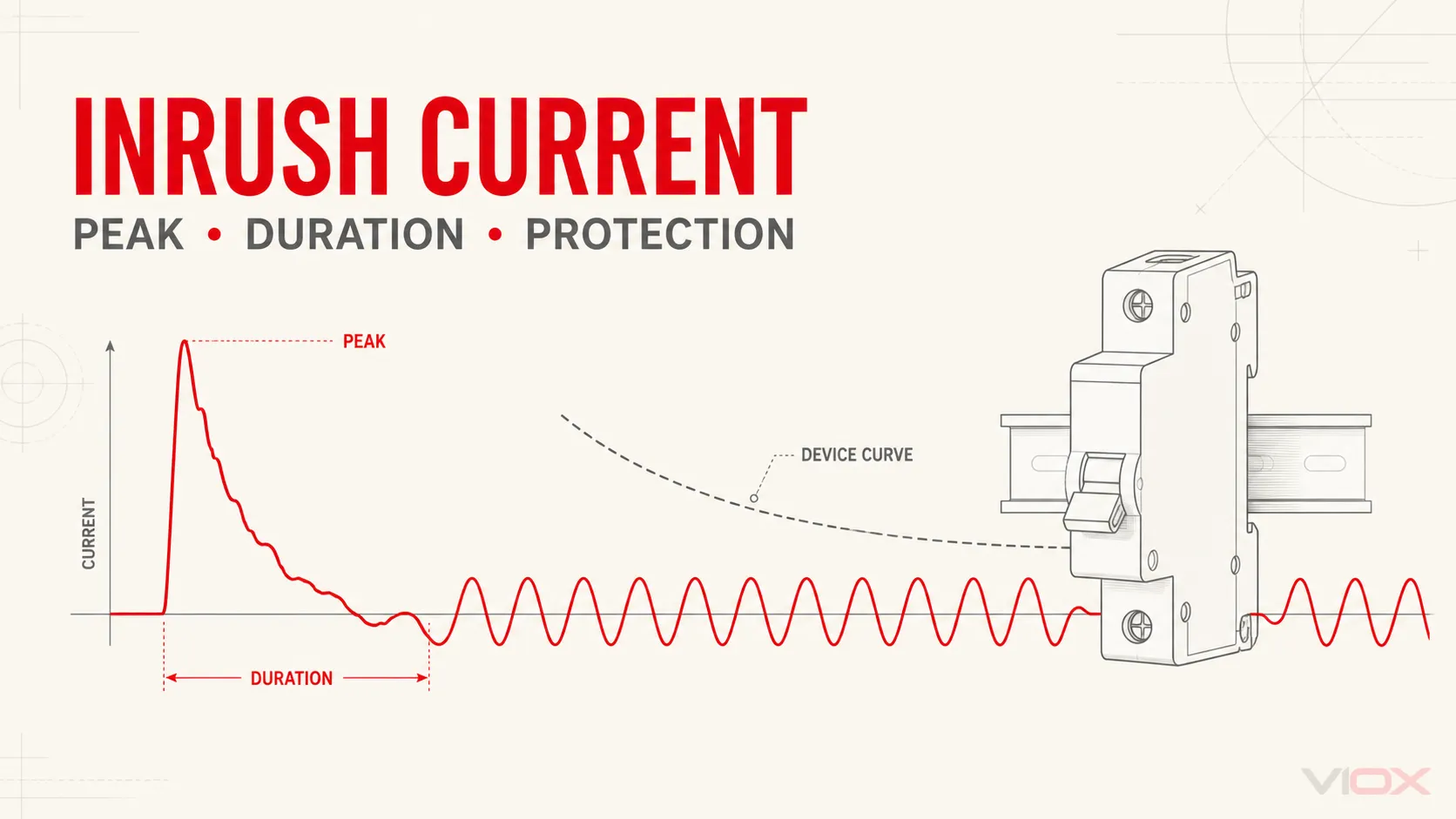
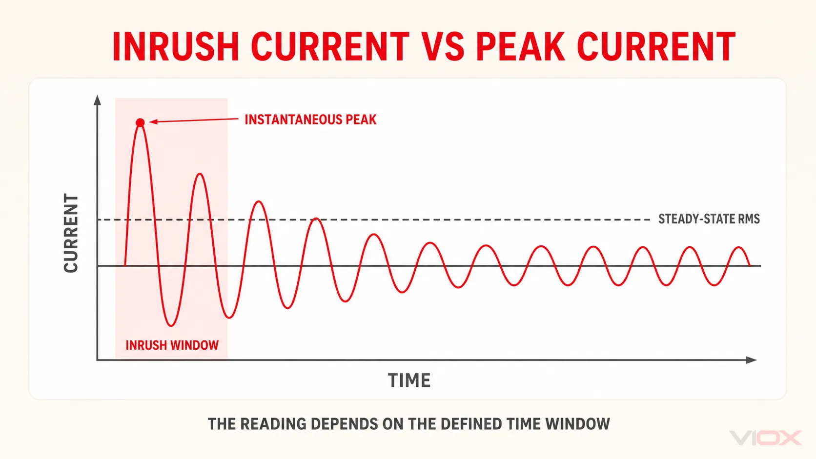
Inrush current is the temporary current drawn immediately after electrical equipment is energized. It can be much higher than the normal operating current, but the magnitude alone does not determine whether a breaker, fuse, contactor, cable, or load is correctly selected. Engineers must evaluate four variables together: peak magnitude, duration, measurement method, and the protective device’s time-current response.
This distinction explains why a clamp meter may display a startup current above a circuit breaker’s ampere rating without the breaker tripping. The event may be brief and remain below the breaker’s operating curve. Conversely, a lower but longer startup current can still produce nuisance tripping or excessive thermal stress.
Key Takeaways
- Inrush current is defined by both current magnitude and time.
- Peak current is a broader term. The highest point of an inrush waveform is a peak current, but not every peak current is inrush current.
- A normal multimeter reading may miss the event. Use an inrush-capable clamp meter or a current probe and oscilloscope when waveform detail matters.
- Generic multipliers are suitable only for preliminary screening. Final coordination needs load data, a defined measurement window, and the protective device’s published curve.
- Do not increase a breaker rating simply to stop nuisance tripping. Cable protection, short-circuit protection, contactor making duty, and selectivity must remain valid.
What Is Inrush Current?
Inrush current is a non-steady-state current that occurs when an electrical load is connected to its supply. The event begins at energization and decays toward the normal operating current as magnetic flux, rotor speed, capacitor voltage, or conductor temperature reaches its operating condition.
The waveform is not the same for every load:
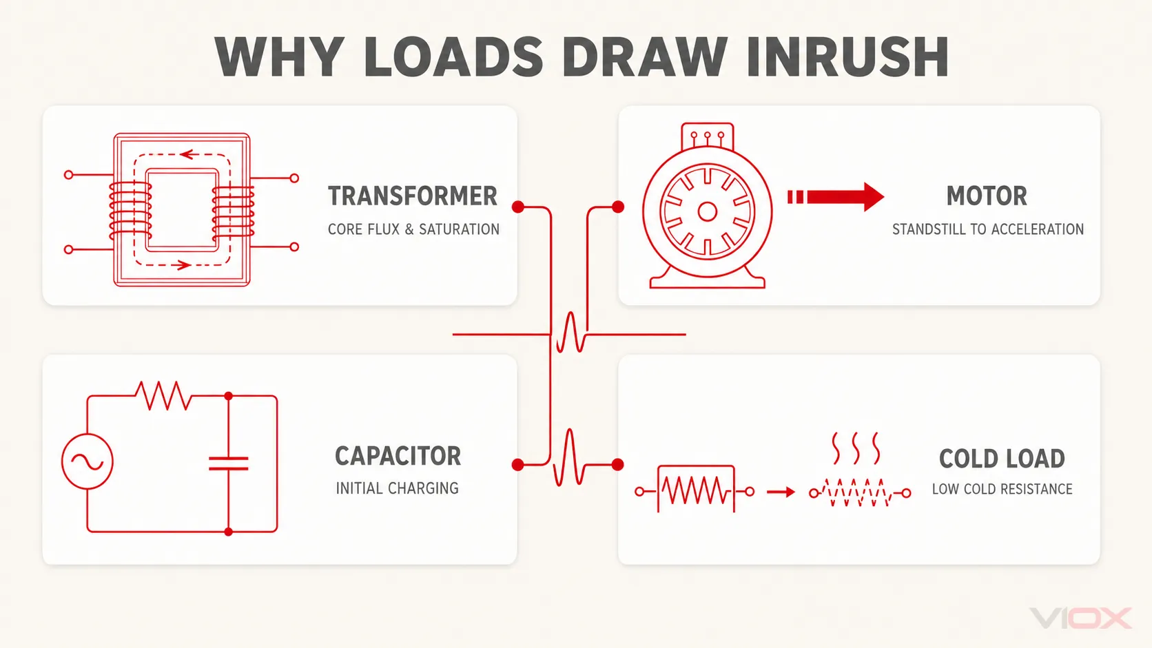
| Load | Main physical cause | Typical waveform behavior | Data needed for coordination |
|---|---|---|---|
| Transformer | Core flux offset and possible magnetic saturation | High, asymmetric magnetizing pulses that decay over several cycles or longer | Manufacturer inrush envelope, closing conditions, source impedance |
| Induction motor | No rotational back electromotive force at standstill | High starting current during acceleration, then decay as speed rises | Locked-rotor current, acceleration time, starting method |
| Capacitor, drive, or switch-mode power supply | Charging an initially uncharged DC-link or input capacitor | Very fast pulse limited by source and circuit impedance or a precharge circuit | Capacitance, source impedance, switching point, precharge behavior |
| Lamp or resistive heater | Cold element resistance is lower than hot resistance | Initial current falls as the element heats | Cold resistance, thermal time constant, switching frequency |
The current may last microseconds in a small electronic input stage, milliseconds in a precharged DC link, several AC cycles in a transformer, or seconds while a heavily loaded motor accelerates. Therefore, a statement such as “the inrush is 80 A” is incomplete unless it also identifies how the value was measured and how long it persisted.
Inrush Current vs Peak Current, RMS Current, and Starting Current
These terms are often mixed together, but they answer different engineering questions.
| Term | Meaning | Typical use |
|---|---|---|
| Inrush current | Temporary current associated with energization | Nuisance-trip analysis, voltage dip, contact making duty, precharge design |
| Instantaneous peak current | Highest instantaneous point within a stated time window | Electrodynamic stress, semiconductor or contact stress, waveform analysis |
| RMS current | Heating-equivalent current over a defined window | Thermal loading, cable and equipment heating, many clamp-meter readings |
| Motor starting current | Current drawn from standstill through acceleration | Motor feeder and starter coordination; may include more than the first transient peak |
| Locked-rotor current | Motor current at rated conditions with the rotor prevented from turning | Motor nameplate and starting studies where applicable |
| Short-circuit current | Fault current resulting from an unintended low-impedance path | Breaking capacity, protection operation, conductor and assembly fault withstand |
The peak of an inrush waveform is one peak-current value. However, “peak current” can also refer to a short-circuit peak, a repetitive semiconductor current, a converter ripple peak, or a circuit breaker’s rated short-circuit making capacity, commonly expressed as Icm in an IEC 60947-2 context. These values are not interchangeable.
The same caution applies to motor terminology. “Starting current” describes the current during acceleration. In casual usage it is often called inrush current, but a protection study should distinguish the initial waveform peak, the RMS locked-rotor or starting current, and the acceleration time.
For a separate explanation of fault-current ratings, see Icu vs Ics vs Icw vs Icm.
Why Electrical Loads Draw Inrush Current
Transformer Energization
A transformer core must establish magnetic flux when the winding is energized. The initial flux depends on the switching angle, supply voltage, residual flux in the core, source impedance, and core characteristics. An unfavorable combination can drive the core into saturation, sharply reducing magnetizing reactance and creating an asymmetric current waveform.
This is why two energizations of the same transformer can produce different peaks. A fixed multiplier cannot represent every closing angle, residual-flux state, or network condition. For final protection coordination, use manufacturer inrush data or a validated electromagnetic-transient model rather than relying only on transformer kVA.
Motor Starting
At standstill, an induction motor has no speed-generated back electromotive force. It draws a high current while producing acceleration torque. The current falls as the rotor accelerates, but its duration depends on supply voltage, load torque, motor inertia, starter method, and mechanical condition.
A motor that starts normally may produce a brief current that the protective device tolerates. A jammed load, low supply voltage, excessive acceleration time, or repeated starts can extend the event and increase thermal stress even if the first peak is unchanged.
Capacitor and Electronic-Load Charging
For an ideal capacitor:
i(t) = C × dv(t)/dtThe relationship shows why a rapid voltage change across a large capacitance produces a high charging current. It does not by itself predict the real peak. Actual current is limited and shaped by source impedance, cable impedance, equivalent series resistance and inductance, rectifiers, switching angle, and any precharge or active current-limiting circuit.
A rough initial screening expression is:
Iinitial ≈ ΔV / ZtotalThis is useful only when Ztotal represents the relevant source and charging-path impedance at the event’s time scale. It should not be treated as a complete design model for a drive, inverter, LED driver, or switch-mode power supply.
Cold Lamps and Heating Elements
The resistance of some metallic filaments and heating elements rises as temperature increases. At switch-on, the cold resistance can be substantially lower than the hot operating resistance, so the initial current is higher. The event then decays as the element warms.
Use the manufacturer’s cold-resistance or switching data when frequent operation, contact life, or protective-device behavior matters. A steady-state wattage alone does not describe the switch-on event.
How Long Does Inrush Current Last?
There is no universal duration. The correct answer is the time required for the specific load to approach its normal operating state.
| Equipment | What determines the duration? | What to verify |
|---|---|---|
| Transformer | Core flux, residual magnetism, network impedance, protection and winding design | Decay envelope over AC cycles and the manufacturer’s energization data |
| Motor | Motor inertia, load torque, available voltage, acceleration method | Current from standstill until stable speed, not only the first cycle |
| Capacitor input | Capacitance, charging resistance, source impedance, precharge control | Pulse width, repetitive switching, and precharge completion |
| Cold resistive load | Thermal mass and temperature coefficient | Time from cold resistance to operating resistance |
When comparing a measured event with a protective device, use the same time basis. A 100 ms triggered RMS reading, a sub-millisecond oscilloscope peak, and a several-second motor-starting RMS trace describe different parts of the event.
How to Measure Inrush Current Correctly
Use an Inrush-Capable Clamp Meter for Repeatable Field Checks
An inrush-capable clamp meter arms a trigger, detects the startup event, and calculates a value over the instrument’s defined capture interval. For example, Fluke describes an inrush function that takes approximately 400 samples over a 100 ms period and calculates the starting current. That value is useful and repeatable for motor troubleshooting, but it is not necessarily the waveform’s highest instantaneous peak.
For a field measurement:
- Confirm that the meter, probe, category rating, and current range are suitable for the circuit.
- Clamp around one current-carrying conductor, not the complete cable containing outgoing and returning conductors.
- Zero or configure the instrument as required by its manual.
- Arm the inrush trigger before energizing the load.
- Record the load condition, supply voltage, start method, capture mode, and repeated results.
- Compare like with like: use the same instrument mode and operating condition for trend data.
Use a Current Probe and Oscilloscope When the Waveform Matters
An oscilloscope with a correctly rated current probe is more appropriate when the task requires:
- the instantaneous peak and its polarity;
- switching-angle effects;
- DC offset or asymmetric transformer current;
- sub-cycle capacitor-charging pulses;
- decay time and repeated pulses;
- correlation with supply-voltage dip or control events.
Probe bandwidth, sampling rate, crest factor, saturation, and safety rating must be adequate. A technically precise graph from an overloaded or bandwidth-limited probe is still a wrong measurement.
Why a Standard Meter May Give the Wrong Impression
A standard current range may average the event, update too slowly, or capture a non-repeatable maximum. Conversely, a meter’s “peak” or “max” function may use a different window from its “inrush” function. Always record the instrument and mode with the value.
Inrush Current Calculation: What Can and Cannot Be Estimated
No single inrush current formula applies to transformers, motors, capacitors, and cold resistive loads. Use a model that matches the physical mechanism.
Motor Preliminary Estimate
For a preliminary motor-feeder study, use manufacturer starting-current or locked-rotor data. When only a valid locked-rotor ratio is available:
Istart,screening = ILR ratio × IratedThis estimates an RMS starting-current level under the stated conditions. It does not predict the first instantaneous peak, acceleration time, voltage depression, or current with a soft starter or variable-frequency drive. Use the motor and starter data for final coordination.
Transformer Preliminary Estimate
A multiplier applied to rated current may be used as a conservative screening assumption only when it comes from the transformer manufacturer, a project specification, or an accepted study method. A complete estimate may need the core’s saturation behavior, residual flux, switching angle, winding data, and source impedance.
The correct procurement request is not simply “What is the inrush multiple?” Ask for the current-versus-time envelope, test or calculation basis, energization conditions, and tolerances.
Capacitor-Charging Estimate
Use i = C × dv/dt to relate charging current to voltage slew rate, or a circuit model using the real charging-path impedance. Confirm whether a precharge resistor, NTC thermistor, controlled rectifier, or active limiter changes the initial circuit.
The stored energy after charging is:
E = 1/2 × C × V²Stored energy helps assess switching and precharge duty, but it is not a direct substitute for peak current or pulse duration.
The Minimum Data Set
Before treating any calculation as a selection input, record:
- supply voltage, frequency, and source impedance;
- equipment type and rated current or power;
- manufacturer startup or energization data;
- peak definition: instantaneous, half-cycle, 100 ms RMS, or another window;
- event duration and decay envelope;
- switching frequency and minimum time between starts;
- ambient and enclosure conditions;
- applicable protective-device standard and exact product curve.
Why Inrush Current Affects Breakers, Fuses, Contactors, and the Supply
Nuisance Tripping
Breakers and fuses respond to current over time. A short pulse may pass without operation while a lower, longer event crosses the device’s operating band. This is why comparing only Ipeak with the device’s rated current is not a valid trip prediction.
For a detailed explanation of operating bands, tolerances, and time-current plots, read Circuit Breaker Trip Curve Explained.
Voltage Dip
A first screening relationship is:
ΔV ≈ Iinrush × ZsourceThe expression indicates why a weak source or long feeder experiences a greater voltage dip for the same current. Actual AC-system voltage drop also depends on the network impedance angle, phase configuration, waveform, and event duration. Nearby contactors, PLC power supplies, lighting, or drives may reset even when the starting circuit itself remains energized.
Contact and Semiconductor Stress
Contactors, relays, switches, rectifiers, and semiconductors may face high making current, repeated pulses, or contact bounce during energization. Their suitability must be checked using the applicable utilization category, making duty, pulse rating, and manufacturer data rather than the steady-state current alone.
For motor feeders, see How to Select Contactors and Circuit Breakers Based on Motor Power.
Thermal and Mechanical Stress
Short pulses can produce local contact heating and electrodynamic force; repeated starts can accumulate heat before equipment returns to ambient temperature. The relevant stress depends on pulse energy, repetition, cooling, and component construction. A single peak-current value cannot quantify all of these effects.
How to Coordinate Protection with Inrush Current
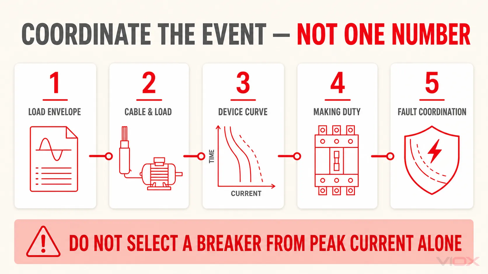
Use the following sequence instead of choosing a larger breaker from a multiplier table.
1. Define the Load Envelope
Obtain or measure the current-versus-time behavior under credible worst-case conditions. Include low supply voltage, loaded starts, residual transformer flux, minimum precharge interval, or cold-start temperature when relevant.
2. Protect the Cable and Load
Confirm that conductor ampacity, overload protection, short-circuit protection, and equipment limits remain satisfied. Increasing the protective-device rating to avoid a startup trip may leave the cable or load inadequately protected.
3. Compare the Entire Event with the Device Curve
Overlay or compare the load envelope with the manufacturer’s time-current curve, including tolerance bands and ambient corrections. Check both the thermal region and the instantaneous or short-time region.
MCB letter curves such as B, C, and D describe instantaneous operating ranges within the relevant product-standard context; they are not universal labels for every breaker. IEC 60898-1 covers specified AC circuit breakers for household and similar installations, while IEC 60947-2 addresses low-voltage circuit breakers intended for operation by instructed or skilled persons. Use the exact device’s standard, datasheet, and curve.
The broader MCB selection guide explains current rating, conductor protection, curve selection, breaking capacity, and coordination.
4. Check Switching and Control Components
Verify contactor or relay making duty, coil voltage during voltage dip, precharge contact rating, and the control sequence. A breaker that remains closed does not prove that every upstream and downstream component can tolerate the event.
5. Verify Fault Protection and Selectivity
An inrush-tolerant setting must still clear faults within the required time and coordinate with upstream and downstream devices. Breaking capacity and short-time withstand are fault-current properties, not inrush ratings.
Protection Review Checklist
| Check | Required evidence | Common error |
|---|---|---|
| Load envelope | Manufacturer curve or validated measurement | Using one undocumented multiplier |
| Measurement definition | Instrument, mode, time window, operating condition | Comparing instantaneous peak with RMS curve data |
| Cable/load protection | Ampacity and equipment protection requirements | Upsizing the breaker to stop trips |
| Device operation | Exact time-current curve and tolerance | Selecting only by B, C, or D letter |
| Making duty | Contactor, switch, relay, rectifier, or semiconductor data | Checking only steady-state current |
| Repetition | Starts per hour and cooling interval | Treating one successful start as continuous suitability |
| Fault coordination | Fault level, clearing time, selectivity, breaking capacity | Confusing inrush peak with short-circuit rating |
Ways to Reduce Inrush Current
| Method | Best suited to | Main limitation or verification point |
|---|---|---|
| NTC thermistor | Smaller capacitor-input and electronic loads | Hot restart may provide less resistance; thermal recovery and losses matter |
| Precharge resistor plus bypass contactor | DC links, drives, chargers, and larger capacitor banks | Control sequence, resistor energy, bypass contact making duty, and failure detection |
| Soft starter | AC induction motors requiring reduced-voltage acceleration | Reduced current also reduces available starting torque; application and ramp settings matter |
| Variable-frequency drive | Motors requiring speed control or managed acceleration | Input rectifier/DC-link inrush still requires the drive’s own precharge design |
| Controlled switching | Transformers or capacitor banks where closing angle is important | Requires system-specific control, sensing, and switching performance |
| Sequential energization | Multiple loads starting together | Adds control complexity and does not reduce each load’s individual inrush |
| Lower-impedance supply or feeder redesign | Systems limited by voltage dip | May increase prospective fault current and require protection reassessment |
Eaton describes a soft starter as a reduced-voltage method for reducing motor inrush. However, the correct ramp must still provide enough torque to accelerate the load without extending the start excessively.
Troubleshooting Unexpected Inrush Trips
- Identify exactly which device operated. Record pole, trip indication, fuse type, relay event code, and upstream/downstream status.
- Confirm when it operated. First energization, hot restart, loaded start, simultaneous start, or during normal running are different diagnostic branches.
- Measure supply voltage and startup current together. A voltage dip can lengthen motor acceleration or cause control components to drop out.
- Record the measurement mode. Do not compare a scope peak with a clamp-meter inrush value as if they were the same quantity.
- Inspect the load condition. Check mechanical binding, incorrect transformer taps, failed precharge circuits, damaged NTC devices, contactor chatter, and unexpected parallel loads.
- Compare with the exact device curve. Include ambient temperature, installation grouping, previous thermal loading, and tolerance.
- Correct the cause before changing protection. Any rating or setting change requires renewed checks of cable protection, fault clearing, selectivity, and equipment limits.
Frequently Asked Questions
Is inrush current the same as peak current?
No. Inrush current is a transient event associated with energization. Its highest instantaneous point is an inrush peak, but peak current is a broader measurement term that can apply to faults, switching, converters, and repetitive waveforms.
Why does a breaker not trip when inrush current exceeds its rated current?
The breaker’s ampere rating and its operating curve serve different purposes. The device responds according to current magnitude and duration within a tolerance band. A brief inrush event may remain below the operating curve even when its measured value exceeds the rated current.
What is the formula for inrush current?
There is no universal formula. Capacitor charging can be described using i = C × dv/dt; motor studies use manufacturer starting or locked-rotor data; transformer studies require energization data or a magnetic-saturation model. Generic multipliers are only preliminary screening assumptions.
How long does inrush current last?
It depends on the load and the definition used. Electronic charging pulses may be very short, transformer inrush may decay over multiple AC cycles, and motor starting current may persist through several seconds of acceleration. State the measurement window with the current value.
Should I choose a D-curve MCB for a high-inrush load?
Not automatically. Confirm the applicable device standard, exact manufacturer curve, cable protection, available fault current, required disconnection time, and selectivity. A curve that tolerates startup must still provide adequate fault protection.
Can a soft starter eliminate motor inrush current?
It can reduce and control starting current, but it does not make the event disappear. Reduced motor voltage also reduces available starting torque, so settings must suit the motor, load, and acceleration requirement.
Engineering Conclusion
Inrush current is not a single multiplier and not merely a large number at switch-on. A defensible design describes the event as a current-versus-time envelope, states how it was measured or calculated, and checks that envelope against cable protection, protective-device curves, switching duty, voltage dip, repetition, and fault coordination.
Use generic estimates to screen a design, not to approve it. For final specification, request the load’s startup or energization data and the exact protective-device curve. If you are coordinating a VIOX breaker, contactor, or control device with a high-inrush load, provide the supply system, load data, measured waveform or manufacturer envelope, and required operating sequence to [email protected].