On this page
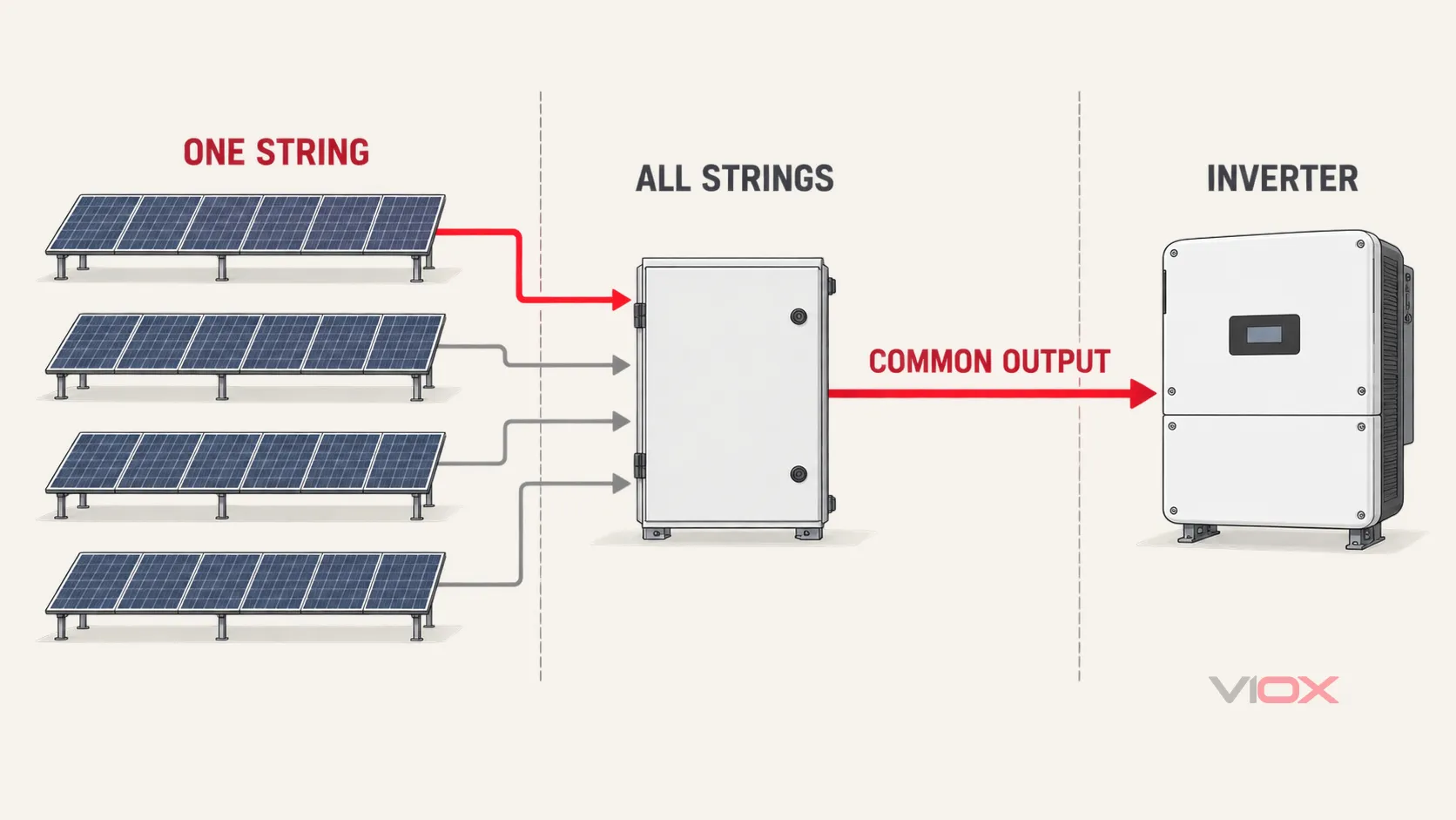
Start by separating a single-string fault from a whole-combiner fault. A missing string usually points to that string circuit, its fuse or breaker, its termination, or the array upstream. Loss of every string points instead to the output circuit, isolator, busbar, downstream cable, inverter state, or a system-wide isolation event.
Do not open the enclosure and begin probing from habit. Photovoltaic modules can continue producing DC whenever they are illuminated, and opening one disconnect may leave other conductors energized. Follow the site-specific energy-control procedure, identify every source, apply lockout/tagout where required, and verify the isolation state before touching internal parts. OSHA’s solar lockout/tagout guidance specifically requires energy sources to be identified, isolated, and verified before service work.
Key Takeaways
- Treat smoke, active arcing, melted insulation, carbon tracking, standing water, or a damaged enclosure as stop-work conditions.
- Compare voltage and current with the array design, inverter records, environmental conditions, and matched peer strings—not with a universal “normal” number.
- A blown fuse or tripped breaker is a symptom. Find the initiating fault before replacing or resetting it.
- Thermal imaging is most useful as a comparative test under known load. The equipment rating and manufacturer instructions determine the allowable temperature, not a generic temperature-difference rule.
- An I-V curve test evaluates a PV string or array. The combiner box may provide a convenient connection point in some architectures, but the test does not certify the combiner box itself.
- Replace heat-damaged, arced, cracked, or materially corroded parts. Tightening or cleaning cannot restore compromised insulation or contact surfaces.
Stop Before Testing: Define the Electrical Boundary
Combiner-box troubleshooting is qualified electrical work. Before opening the box, review the single-line diagram, string schedule, inverter event log, previous inspection records, and the instructions for the exact combiner, fuse holders, breakers, isolator, surge protective device (SPD), and monitoring module.
A local DC isolator does not automatically make every internal point safe. Depending on the topology, the array side can remain energized in sunlight, and a downstream conductor may be subject to another source or stored energy. The isolation plan must match the actual installation, not a generic diagram.
Stop and escalate when any of the following is present:
- smoke, active arcing, crackling, or a burning odor;
- melted insulation, carbonized material, or severe discoloration;
- standing water or wet live-part compartments;
- a cracked enclosure, failed door, or cable entry that no longer retains conductors;
- an unexplained insulation or ground-fault alarm;
- repeated operation of the same fuse or breaker after an attempted reset;
- missing drawings, labels, or device ratings needed to identify the circuit safely.
IEC 62446-2 covers preventive, corrective, and performance-related maintenance of grid-connected PV systems, including worker safety and troubleshooting. Its scope reinforces the central rule here: a maintenance action must be part of a documented PV-system process, not an isolated component guess. See IEC 62446-2:2020.
Fast Diagnostic Matrix
| Symptom | First safe check | What the result suggests | Next action |
|---|---|---|---|
| One string reports zero or unusually low current | Compare its monitoring record, open-circuit voltage, polarity, and protection-device state with matched strings | Correct voltage but no operating current points toward an open circuit, fuse/holder, breaker, termination, or monitoring issue; low voltage shifts attention upstream to the string | Isolate that string circuit, inspect the termination and protection path, then test the string separately if required |
| Every string is lost | Check inverter status, output isolator or breaker state, combiner output voltage, and downstream continuity under the approved procedure | Normal string inputs with no output points to the common bus, output device, or downstream circuit | Keep the box isolated and trace the common output path |
| Fuse opens or breaker trips again | Review polarity, conductor damage, reverse-current exposure, device rating, temperature conditions, and fault history | Repeated operation means the cause remains; it is not evidence that the protective device is “too small” | Do not up-rate the device as a shortcut; resolve the design or fault condition first |
| One termination is much hotter than comparable loaded points | Confirm comparable current, inspect the conductor preparation and contact area after isolation, and check the specified torque record | A localized hot spot suggests abnormal contact resistance or damaged hardware; uniform heating suggests load, derating, or enclosure conditions | Replace damaged parts and remake the connection to the exact instructions; use the dedicated overheating guide for design-level causes |
| Inverter reports insulation or ground fault | Use the approved isolation sequence to divide the array into sections; review moisture and cable-damage history | A fault that follows one string is likely upstream of the combiner; a fault remaining on the output side shifts attention to the combiner or homerun | Perform insulation testing only with sensitive equipment isolated and an approved test voltage |
| SPD indicator or remote contact changes state | Confirm the exact SPD status indication and inspect for signs of surge or thermal damage after isolation | A changed indicator can show the SPD module’s internal disconnector has operated; it does not prove the rest of the installation is undamaged | Replace only with the specified compatible module and inspect the associated protection and earthing path |
| Fault appears after rain or overnight condensation | Inspect seals, glands, drain or breather provisions, water tracks, corrosion, and cable entry orientation | Moisture-related timing points toward an enclosure or entry-system failure, but wet cables or modules can also create an upstream insulation fault | Do not re-energize a wet or corroded assembly; restore the complete environmental protection and replace affected parts |
| Electrical output is normal but SCADA data is missing | Check auxiliary supply, communication wiring, addressing, termination, and gateway status | The power circuit may be healthy while monitoring is unavailable | Repair the monitoring channel and confirm alarms before closing the work order |
1. One PV String Is Missing or Weak
Begin with the monitoring history, if available. Determine whether the change was sudden, gradual, irradiance-dependent, or associated with recent work or weather. Compare only strings with the same module type, series count, orientation, and similar irradiance.
After the approved isolation and verification steps, trace the affected circuit through its input terminal, fuse holder or breaker, bus connection, and monitoring sensor. A correct-looking open-circuit voltage does not prove that the circuit can carry current. An open or high-resistance connection can show plausible voltage with no load and collapse when the inverter draws current.
Use operating-current comparison when the system can be measured under the approved energized-work procedure and stable conditions. If the combiner path is intact but the string remains an outlier, move the investigation upstream to connectors, module junction boxes, conductors, shading, bypass-diode behavior, or module damage. The combiner is then a test boundary, not necessarily the failed component.
For an open fuse circuit, follow the separate guide on how to test a bad DC fuse in a PV system. PV fuse-links have application-specific requirements; IEC 60269-6 covers fuse-links intended to protect PV strings and arrays up to 1,500 V DC. Replace a fuse only with the specified PV/DC type and rating after identifying why it opened.
2. The Entire Combiner Has No Output
When all strings disappear together, do not test every module first. Check the common path:
- Confirm whether the inverter or downstream DC equipment has intentionally disconnected the input.
- Verify the state of the combiner output isolator, breaker, or switch-disconnector using the device’s own instructions.
- Compare individual string-side readings with the common output reading at approved test points.
- Inspect the output terminals, busbars, and downstream cable for an open connection, heat damage, or an isolation event.
Normal string-side voltage with no common output narrows the problem to the combiner’s common circuit or its immediate downstream path. No voltage on any input points away from the common bus and toward the array state, an upstream isolation action, a documentation error, or an incorrect test condition.
3. A Fuse Opens or a Breaker Trips Repeatedly
Protective-device operation is evidence of a condition, not a repair instruction. Before replacement or reset, check:
- whether the device is correctly specified for PV DC duty and the actual system voltage;
- whether polarity and pole arrangement match the design;
- whether conductor insulation or connectors show damage;
- whether parallel strings can drive reverse current into a faulted string;
- whether the device and enclosure are operating within documented temperature and current conditions;
- whether the event followed lightning, maintenance, rewiring, or module replacement.
Do not solve repeated operation by installing a higher-rated device without a fresh protection calculation. That can remove protection from the conductor or module circuit. For thermal nuisance operation, use the combiner-box fuse temperature-derating guide and the exact device manufacturer’s data.
4. A Terminal, Fuse Holder, or Bus Connection Is Hot
Under known load, compare equivalent points serving similar strings. A single hot termination is more diagnostic than a general rise throughout a sun-heated enclosure. Check current at the hot circuit so a high-load condition is not mistaken for a connection defect.
After isolation, inspect for loosened hardware, conductor strands outside the clamping area, incorrect lug or ferrule use, oxidation, pitting, softened polymer, or discoloration. Use only the torque value and conductor-preparation method specified for the exact terminal. Do not “retorque” a visibly heat-damaged connection and return it to service; the contact plating, spring force, insulation, or conductor may already be compromised.
For thermal design, enclosure exposure, and derating analysis, see Solar Combiner Box Overheating: Root Causes and Solutions. This troubleshooting page owns the fault-isolation decision, not a universal temperature limit.
5. The Inverter Reports an Insulation or Ground Fault
First determine whether the alarm identifies a measured insulation condition, a residual-current condition, an arc-fault event, or a model-specific diagnostic code. These are not interchangeable.
Use the approved isolation procedure to divide the DC system into progressively smaller sections: downstream cable, combiner output, individual string circuits, and then the array upstream. A fault that follows one isolated string points outside the combiner. A fault that remains with all strings disconnected shifts attention to the common circuit, SPD connection, internal wiring, or downstream homerun.
Insulation-resistance testing can damage SPDs, monitoring electronics, inverters, module-level power electronics, or other connected equipment if they are not isolated as required. Use the test voltage, connection method, acceptance value, and environmental correction required by the project documentation and equipment manufacturers. Do not apply a universal pass/fail value copied from another system.
6. The SPD Shows a Fault State
A PV DC SPD is intended to limit transient overvoltage and divert surge current; it does not clear a sustained short circuit. IEC 61643-31:2018 covers SPDs intended for the DC side of PV installations up to 1,500 V DC.
Read the indicator and remote-contact behavior from the exact SPD instructions. After isolation, inspect the module, base, backup protection, conductors, and protective-earth connection for thermal or surge damage. Replace a plug-in cartridge only with the compatible type specified for that base. A green replacement indicator does not by itself verify the earthing path, lead routing, backup protection, or condition of other equipment after a surge event.
7. Faults Appear After Rain or During High Humidity
Track the water path instead of only drying the enclosure. Inspect the door seal, hinges, latches, cable glands, unused openings, conduit entries, breather or drain arrangement, and mounting damage. Water staining and corrosion often reveal an earlier ingress event even when the box is dry during inspection.
Replace terminals, fuse holders, SPDs, conductors, or bus hardware when corrosion affects the contact area, plating, insulation, or mechanical strength. Restore the environmental rating as a complete installed assembly; a correctly rated enclosure can lose that protection through an incorrect gland, unsealed opening, damaged gasket, or poor mounting.
8. Monitoring Is Offline but Power Is Still Present
Separate the measurement system from the power path. Check auxiliary power, string-current sensors, communication polarity, shielding, network termination, device address, baud rate, gateway state, and recent configuration changes. Confirm that a sensor or channel mapping error is not presenting a healthy string as zero current.
Restore monitoring before closing the fault when alarms and string comparison are part of the plant’s protection or maintenance strategy. A producing array with blind monitoring is not the same as a fully verified system.
What Each Test Can—and Cannot—Prove
| Test | Useful for | Does not prove |
|---|---|---|
| Open-circuit voltage (Voc) | Polarity, approximate series count, open-circuit comparison, and locating an open section | Current-carrying ability, contact quality under load, or full string power |
| Operating current | Comparing matched strings under similar irradiance and inverter conditions | Module health when irradiance, orientation, or MPPT conditions differ |
| Continuity or resistance on an isolated component | Finding an open fuse, conductor, or contact path | Safe operation at rated PV voltage and current |
| Insulation resistance | Localizing leakage between current-carrying conductors and earth after correct isolation | The exact physical fault location without further sectional testing |
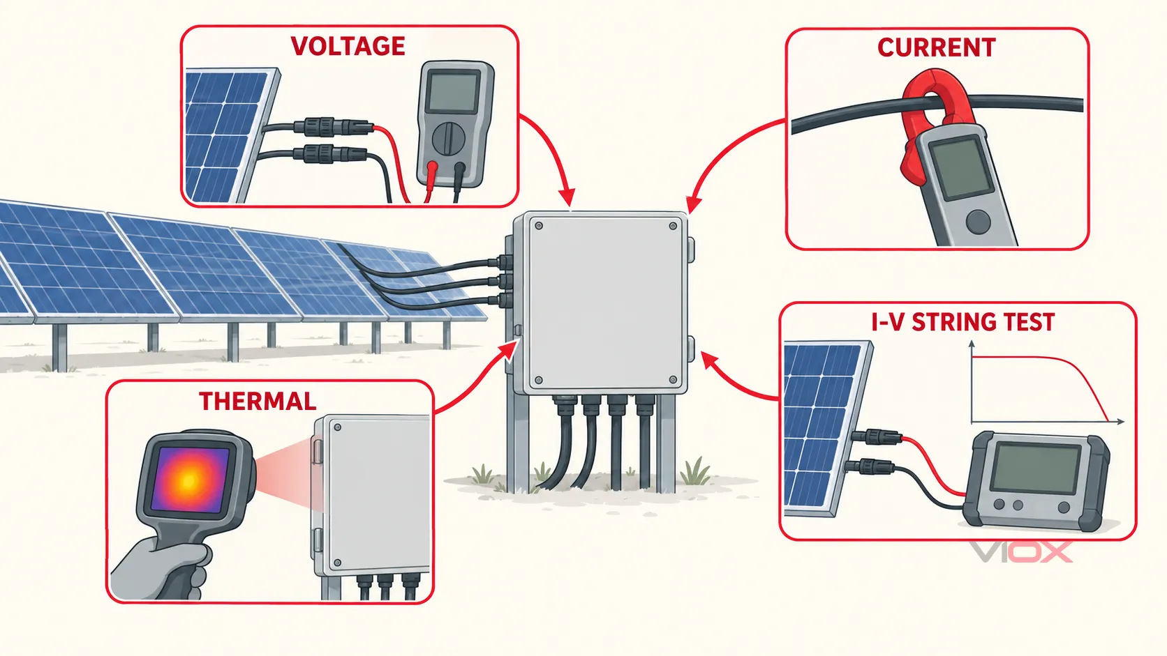
| Thermal imaging | Finding abnormal heat patterns under known load and tracking change over time | A universal pass/fail temperature independent of load, ambient conditions, emissivity, and component rating |
| I-V curve tracing | Characterizing a PV string or array and distinguishing current, voltage, mismatch, shading, or series-resistance behavior | The health or certification of the combiner-box assembly itself |
When I-V Curve Testing Helps
IEC 61829:2015 specifies procedures for on-site measurement of PV array current-voltage characteristics and the accompanying meteorological conditions. The IEA PVPS mobile-test-equipment report explains that an I-V analyzer may connect to PV string terminals inside field combiner boxes or to DC cables entering the inverter, depending on the plant architecture and isolation procedure.
Use I-V tracing after basic protection, polarity, and connection checks show that the combiner path is intact but a string still underperforms. The result diagnoses the PV source circuit; it should not be described as an “I-V test of the combiner box.”
Repair or Replace?
| Finding | Repair may be reasonable when | Replace the component or assembly when |
|---|---|---|
| Loose termination | No heat, arc, corrosion, thread, conductor, or insulation damage is present, and the connection can be remade to the exact instructions | There is pitting, carbon tracking, melted polymer, damaged plating, weakened spring force, stripped hardware, or annealed conductor |
| Open fuse | The initiating fault is identified and the holder is undamaged | The holder is overheated, cracked, loose, or no longer compatible with the specified replacement |
| Breaker or isolator operation | The external fault is corrected and the device passes the manufacturer’s inspection or test criteria | The device has arc damage, abnormal mechanism behavior, heat damage, or repeated unexplained operation |
| Water ingress | The source is corrected and all affected parts remain clean, dry, mechanically sound, and verifiable | Corrosion reaches electrical contacts or busbars, insulation is damaged, seals cannot be restored, or the enclosure is deformed or cracked |
| SPD fault indication | A compatible replaceable module is specified and the base and conductors are undamaged | The base, backup protection, conductors, or enclosure show thermal or surge damage |
| Missing documentation | Exact model records and ratings can be recovered | Safe rating, wiring, torque, or replacement compatibility cannot be established |
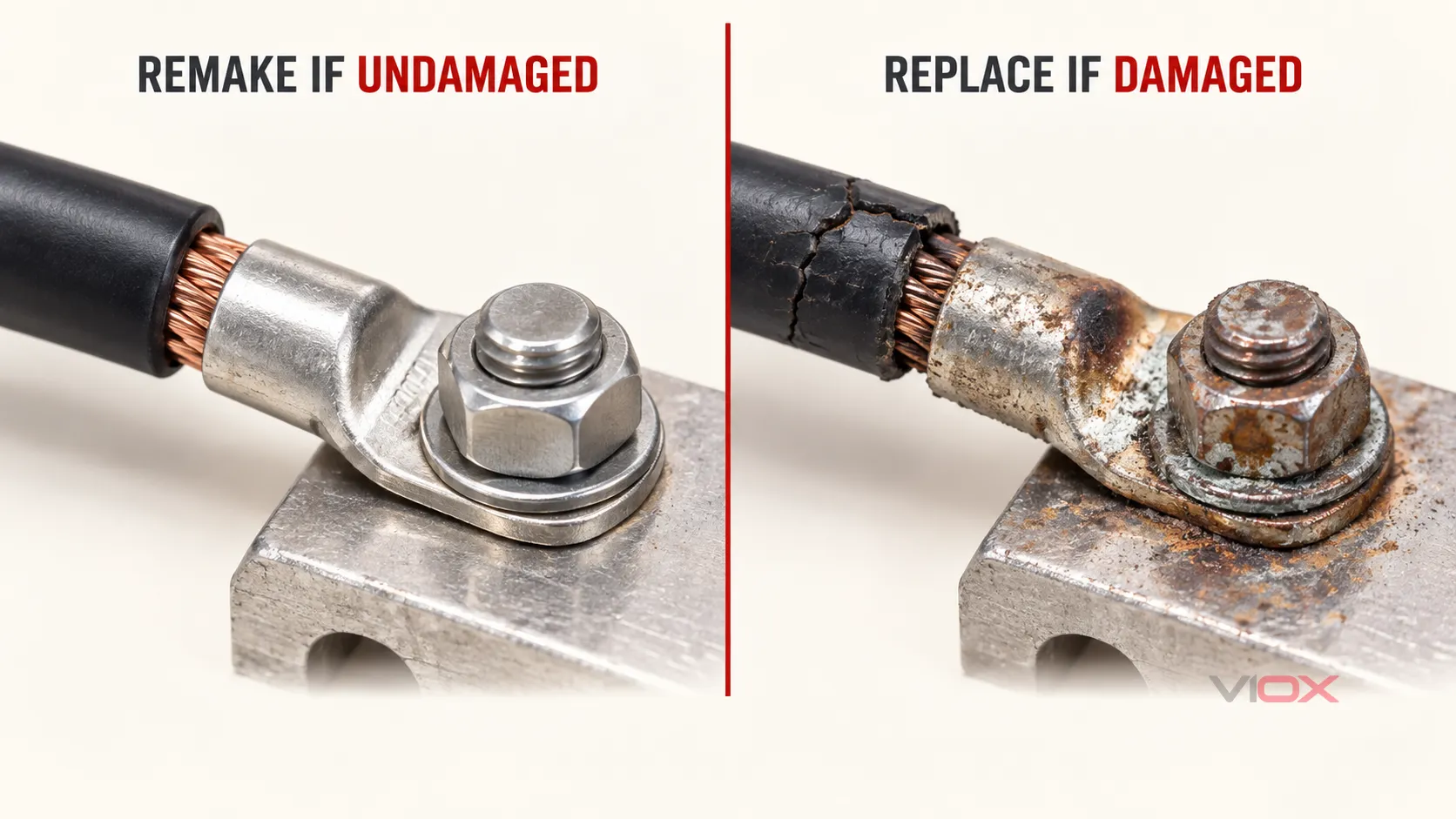
Replace the complete box when damage is widespread, the bus structure or enclosure is compromised, multiple components have aged or failed together, or restoring the original ratings cannot be demonstrated.
Return-to-Service Verification
Before energization, confirm that:
- the identified root cause—not only the visible symptom—has been corrected;
- replacement parts match the approved voltage, current, DC-duty, environmental, and compatibility requirements;
- polarity, conductor routing, protective-earth connections, labels, barriers, covers, glands, and unused openings are restored;
- terminations are completed to the exact manufacturer instructions and recorded values;
- tools, temporary grounds, jumpers, locks, and foreign materials are accounted for under the site procedure;
- the enclosure closes correctly and its sealing system is intact;
- string and output readings are plausible against the design and peer circuits after controlled re-energization;
- inverter alarms, SPD status, and monitoring channels return to the expected state.
IEC 62446-1 describes commissioning tests, inspection criteria, and documentation expected to verify safe installation and correct operation of grid-connected PV systems. Use the same documentation discipline after a material repair; see IEC 62446-1:2016.
Prevent the Same Fault from Returning
Record the symptom, environmental conditions, alarm history, isolation points, readings, photographs, parts replaced, torque values from the applicable instructions, and post-repair verification. Trend string current, thermal images, moisture evidence, and repeated protective-device events rather than relying on a fixed generic maintenance interval.
Use the site’s risk assessment, equipment instructions, operating environment, and fault history to set inspection frequency. The solar combiner box inspection checklist can support scheduled checks, while the PV combiner box guide provides the wider protection and component context.
If the existing assembly cannot be restored with verifiable ratings and documentation, compare the required string layout, voltage class, protection functions, monitoring needs, and environment with the VIOX solar PV combiner box range, then request documentation for the exact configuration before selection.
Sources
- OSHA — Solar Energy: Lockout/Tagout
- IEC 62446-1:2016 — PV system documentation, commissioning tests, and inspection
- IEC 62446-2:2020 — Maintenance of grid-connected PV systems
- IEC 61829:2015 — On-site measurement of PV array I-V characteristics
- IEA PVPS T13-24:2021 — Qualification of PV power plants using mobile test equipment
- IEC 60269-6:2010+A1:2021 — Fuse-links for PV strings and arrays
- IEC 61643-31:2018 — SPDs for photovoltaic installations