On this page
An elevator should be protected by electrical interface, not by one generic “elevator SPD.” Begin with the incoming supply and the disconnecting means covered by the adopted electrical code. Then assess controller and auxiliary power, exposed copper control or communication lines, remote equipment, alternate sources, and the bonding path as separate surge boundaries.
A conventional power surge protective device (SPD) belongs on a compatible power input—not automatically on a variable-frequency drive (VFD) output. The exact locations, protection modes, ratings, backup protection, and coordination must come from the adopted code, elevator-system documentation, SPD instructions, and the project’s electrical study.
Safety boundary: Elevator equipment can contain hazardous voltages, stored energy, multiple supplies, moving machinery, and safety circuits. Only qualified persons following the elevator manufacturer’s procedures, the site’s lockout/tagout program, and applicable codes should inspect or modify it. An SPD is not a substitute for elevator safety devices, overcurrent protection, grounding, bonding, or required maintenance.
Why One Panel SPD Is Not the Complete Elevator Protection Boundary
An elevator installation is a connected system. Depending on the design, conductive paths can include:
- the normal AC supply;
- an emergency or legally required standby supply;
- controller and auxiliary-control power;
- a VFD or other motor-control input;
- copper fire-alarm, monitoring, intercom, telephone, access-control, or building-management interfaces;
- travelling cables and remote landing equipment;
- protective-earth, bonding, shield, and equipment-enclosure connections.
A surge can enter through one path and leave through another. Protecting only the phase conductors at a distant distribution board may still leave a damaging voltage difference between controller power and an unprotected signal port, or between a cabinet reference and a remote copper cable.
This is the core design rule:
Every conductive path crossing a protection boundary must be documented, assessed, and either protected with compatible equipment or justified as not requiring an SPD.
The process does not mean installing an SPD everywhere. It means avoiding an undocumented path that bypasses the intended protection.
The Elevator Surge-Protection Boundary Matrix
Use the following matrix before selecting product ratings. It separates five engineering decisions that are often collapsed into one purchasing question.
| Boundary | What crosses it | Primary question | Evidence required | Stop condition |
|---|---|---|---|---|
| Incoming power or elevator disconnect | Normal or alternate-source power conductors and PE/bonding path | Does the adopted code require an SPD here, and what surge duty applies? | Adopted code edition, one-line diagram, system voltage and earthing arrangement, lightning-protection context, available fault current, SPD product data | Code edition, source arrangement, protection modes, or fault current is unknown |
| Controller and auxiliary power | Controller supply, transformer or power supply input, brake/control auxiliaries | Is the controller at the same protected node as the upstream SPD, or does it need a coordinated downstream stage? | Controller manual, cable route, equipment impulse-withstand information, upstream/downstream coordination data | Equipment withstand or exact connection path is unknown |
| Drive input | AC line side of a VFD or motor drive | Is the line-side SPD compatible with the drive and upstream protective system? | VFD manufacturer instructions, input topology, upstream SPD data, short-circuit and backup-protection information | Proposed location is the VFD output, or the drive maker does not approve the arrangement |
| Copper signal and communication paths | Monitoring, intercom, fire alarm, BMS, access control, remote I/O, exposed control wiring | Can a transient create a voltage difference between the signal reference and powered equipment? | Interface voltage/current, bandwidth or data rate, pin/pair arrangement, shielding and earthing method, signal-SPD data | Protocol and electrical interface are identified only by connector name |
| Remote equipment and alternate sources | Travelling cable, landings, machine-room links, standby supply, battery lowering or other auxiliary source | Does another path enter the protected zone or remain energized when the normal supply is isolated? | Full source schedule, isolation scheme, cable route, manufacturer diagrams, commissioning procedure | A source or conductive route is omitted from the isolation and protection drawings |
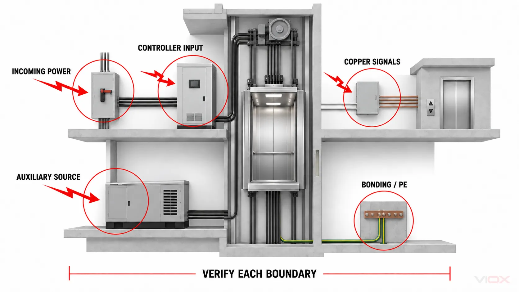
The matrix is deliberately product-neutral. A Type label or a high kA number cannot answer all five rows.
Check the Adopted Code Edition Before Selecting the SPD
Code statements about elevators must be tied to an edition and jurisdiction.
An official NFPA record for the 2023 NEC development cycle shows Article 620.51(E) requiring a listed SPD where the elevator disconnecting means supplies an emergency-system, legally required standby-system, or critical operations power-system load, with installation in accordance with Part II of Article 242. The wording and scope have changed between editions, and local adoption can lag or amend the model code. Verify the project’s adopted text in NFPA LiNK and confirm the interpretation with the authority having jurisdiction (AHJ).
That code check answers only part of the design question. It does not establish:
- the correct SPD voltage rating or protection modes;
- whether another SPD is needed at a controller or remote node;
- compatibility with a specific VFD;
- protection for signal and communication interfaces;
- coordination with upstream SPDs and backup protection.
Elevator-specific responsibilities also remain in scope. The ASME A17 standards overview identifies A17.1/CSA B44 as the safety code for elevators and escalators and A17.5/B44.1 as covering elevator and escalator electrical equipment. Use the applicable elevator code, listed-equipment documentation, and manufacturer instructions together with the electrical code. Do not let a generic SPD drawing override a controller or elevator-system instruction.
Protect the Main Supply and Disconnecting-Means Boundary
At the incoming-power boundary, collect the system facts before choosing a device:
- Nominal and maximum continuous voltage: include normal tolerance and the voltage appearing across each proposed protection mode.
- System and earthing arrangement: document phase-to-phase, phase-to-neutral, and phase/neutral-to-PE relationships that affect topology.
- Installation boundary: identify whether the location is at service equipment, a feeder, an elevator disconnect, or a downstream controller panel.
- Surge environment: record external lightning-protection context, exposed feeders, building entry routes, and upstream protection.
- Available fault current: verify the SPD’s short-circuit rating and any required backup fuse or circuit breaker at the actual connection point.
- Protection objective: identify the equipment and impulse-withstand objective at the protected node.
For AC low-voltage power SPDs in the IEC framework, IEC 61643-11:2025 provides the relevant product-requirement and test-method scope. A declaration to that standard still does not select the product for the project; the exact Uc, Up, discharge-current quantities, protection modes, temporary-overvoltage behavior, disconnection arrangement, and short-circuit data must be checked in the manufacturer’s documentation.
Do not size the elevator SPD by copying a kA value from another building. The separate SPD kA sizing guide explains why voltage compatibility, protection level, installation category, short-circuit safety, and coordination act as gates before current rating becomes a meaningful comparison.
Protect the Controller and the VFD Input—Not the Drive Output by Assumption
Elevator controllers combine power electronics, control power supplies, processors, I/O, communication ports, and safety-related circuits. Their susceptibility is therefore not represented by the motor voltage alone.
First, determine whether the controller is electrically close enough to the upstream SPD to share the same protected node under the applicable design method. A long or routed conductor can add inductive voltage, pick up coupled disturbances, or create another boundary. If a downstream SPD is proposed, it must coordinate with the upstream device; simply placing a smaller Type 2 or Type 3 unit nearer the controller does not prove energy coordination.
Second, treat the VFD line side and load side differently:
- Line side: a suitably selected and coordinated SPD may protect the incoming supply boundary, subject to the drive and SPD manufacturers’ instructions.
- DC link or internal nodes: do not modify or add protection unless the drive manufacturer explicitly provides for it.
- Motor output: a conventional mains SPD should not be added by analogy. VFD outputs contain PWM waveforms and can experience reflected-wave and
dv/dtstress. Drive-approved reactors, filters, cable practices, and motor-insulation measures solve a different problem.
The VIOX guide to VFD surge-protector selection covers that drive-specific boundary. This elevator page does not replace the VFD manual or claim that an SPD prevents every drive failure.
Protect Signal and Communication Paths as Separate Interfaces
A power SPD and a signal-line SPD are not interchangeable. They operate at different normal voltages, current levels, impedances, frequencies, and connector or pair arrangements.
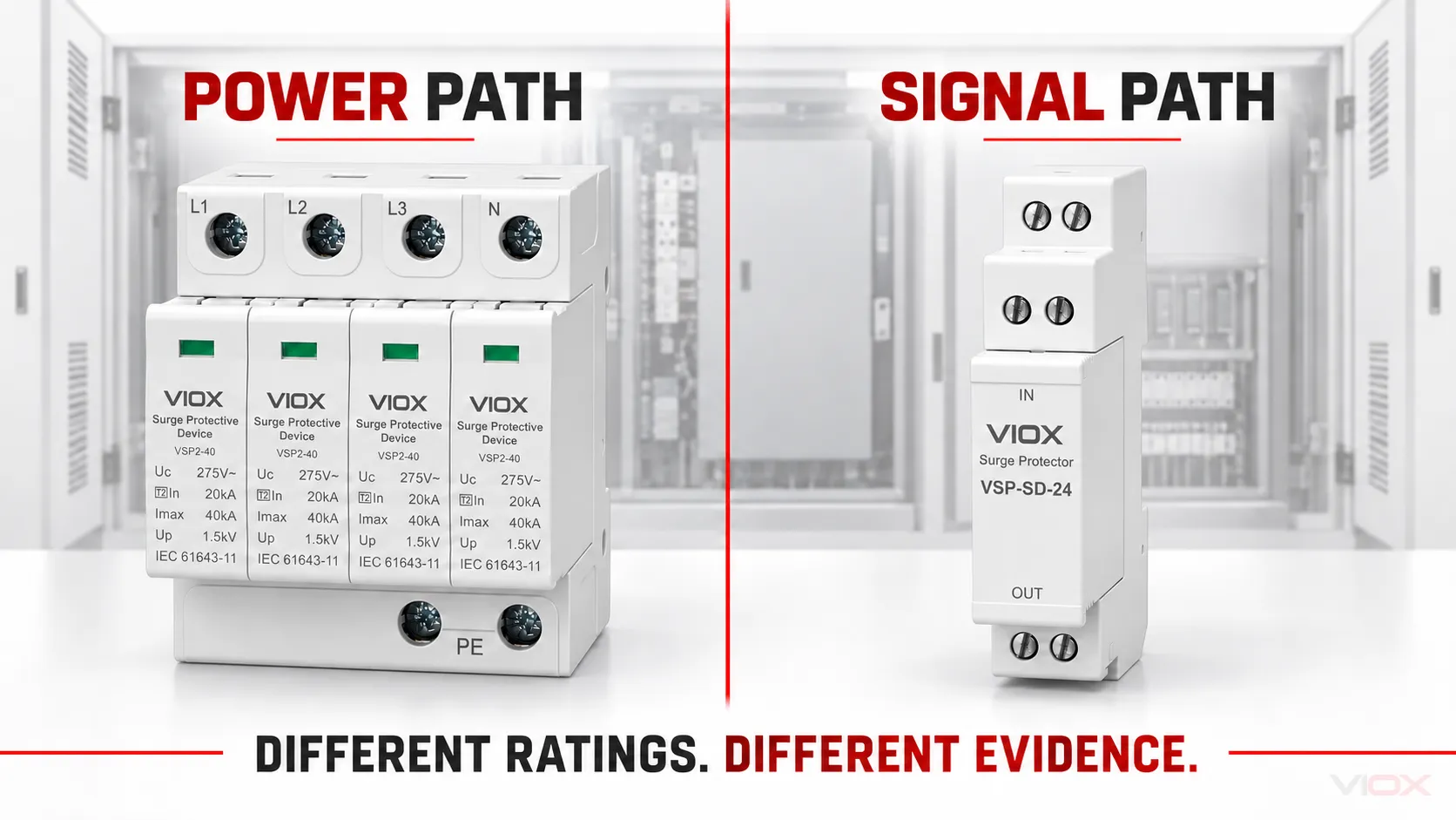
For every copper interface leaving the controller cabinet or crossing between building zones, record:
- interface function and equipment at both ends;
- maximum continuous signal or supply voltage;
- normal and fault current;
- data rate, frequency range, or allowable insertion loss;
- number of conductors, pairs, and protection modes;
- shield termination and bonding arrangement;
- isolation already provided by the connected equipment;
- expected surge test or environment;
- allowable residual voltage at the protected port.
IEC 61643-21:2025 covers requirements and test methods for SPDs connected to telecommunications and signalling networks. IEC 61643-22:2015 addresses selection and application principles for those networks. These scopes confirm why a power-SPD datasheet is insufficient for a copper signal port.
Do not select a signal SPD from the connector name alone. Two ports with similar connectors may use different pin assignments, common-mode voltage, bandwidth, shielding, or isolation. Use the exact interface data and follow the dedicated signal surge protector selection guide.
Where an optical-fibre link provides no conductive signal path, it can reduce one coupling route, but power, shields, metallic strength members, enclosures, and equipment bonding still need assessment. “Fibre” does not automatically make the entire remote installation surge-proof.
Account for Emergency, Standby, and Auxiliary Sources
An elevator may have more than one energized source or an auxiliary system that remains active when the normal supply is disconnected. The design team should build a source schedule, not assume that opening one disconnect removes every transient path.
For each source, identify:
- its origin and transfer arrangement;
- the conductor set and bonding reference;
- where it enters the elevator equipment boundary;
- whether an existing upstream SPD protects that route;
- how protection remains coordinated in every operating state;
- how maintenance personnel verify isolation.
This is especially important when the normal source, alternate source, controller auxiliaries, remote monitoring, or battery-backed functions have different disconnection points. The article does not prescribe a topology because elevator designs differ; the project drawings and manufacturer documentation must show it.
Select Ratings With an Evidence Schedule, Not a Generic Recipe
Once the boundaries are mapped, complete one evidence row for every proposed SPD.
| Selection field | What to document | Why it matters |
|---|---|---|
| Exact location and protected equipment | Panel, disconnect, controller input, remote interface, or other named node | Prevents a product from being approved without a defined protection job |
| Product standard and classification | Applicable UL, IEC, or other adopted product standard; Type/test class | Establishes the test framework, not automatic project suitability |
| Normal-voltage compatibility | Uc, MCOV, or interface working voltage by protection mode |
Avoids operation or degradation during normal system conditions |
| Protection performance | Up, VPR, measured limiting voltage, or signal limiting data under the applicable framework |
Relates the device result to the equipment withstand objective |
| Discharge duty | Iimp, In, Imax, Uoc, or applicable signal-port test quantities |
Must match the boundary and test framework; the values are not interchangeable |
| Temporary-overvoltage behavior | Published TOV or abnormal-voltage behavior where applicable | Separates brief surge duty from longer power-system abnormalities |
| Short-circuit and backup protection | SCCR, Isccr, follow-current or backup-device instructions as applicable |
Ensures the SPD can be safely connected at the actual fault level |
| Coordination evidence | Exact upstream/downstream pair, spacing or decoupling instructions, and protected-node check | A sequence of Type labels does not prove a coordinated system |
| Environmental and mechanical limits | Temperature, enclosure, altitude, contamination, vibration, mounting, conductor and torque limits | Confirms the installed environment matches the product instructions |
| Status and service evidence | Local indicator, removable module, remote contact, replacement criteria | Defines what maintenance can actually observe and record |
Where a requirement is unknown, mark it open. Do not replace missing equipment withstand, fault-current, or coordination data with a larger kA number.
The SPD coordination and cascading guide provides the four-gate verification method for voltage, energy, distance, and fault coordination. The general SPD installation requirements guide covers code and installation evidence beyond this elevator application.
Installation Details Can Change the Protection Result
An SPD’s declared protection level is not necessarily the voltage that appears at the equipment terminals. Connection conductors carrying surge current add inductive voltage, and the protected equipment may not share the same reference point as the SPD.
At each selected boundary, verify:
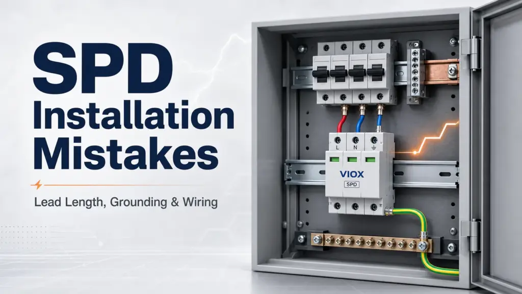
- the complete surge-current loop is short, direct, and routed according to the SPD instructions;
- line and PE/bonding connections do not create an unnecessary loop area;
- protected and unprotected conductors are separated to limit recoupling;
- the SPD is connected on the correct side of the disconnect or overcurrent device under the adopted rules and manufacturer instructions;
- backup protection matches the exact SPD documentation and available fault current;
- the enclosure and mounting provide the required environmental protection;
- signal-SPD bonding and shield treatment match the interface design;
- the installed device remains accessible for inspection or replacement without defeating elevator safety procedures.
Do not turn “short leads” into an unverified universal length. Record the actual route and check it against the product and project requirements.
Commissioning Must Prove the Installation, Not Simulate a Lightning Strike
Commissioning is a documentation and inspection task. It is not an instruction to inject a high-energy impulse into installed elevator equipment.
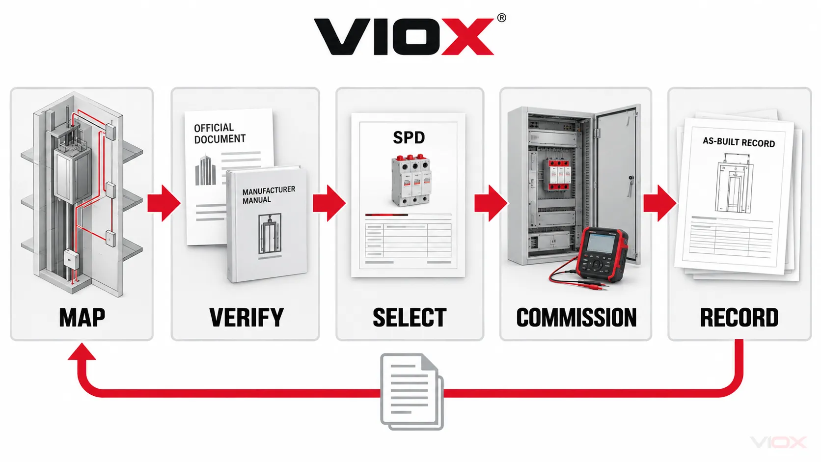
The handoff record should include:
- approved one-line and interface-boundary drawings;
- exact SPD manufacturer, model, option suffix, product standard, and datasheet revision;
- protection modes and declared electrical ratings;
- approved backup fuse or circuit breaker and available-fault-current check;
- upstream/downstream coordination evidence;
- as-installed conductor route, termination, torque record where required, and photographs;
- local indicator state and any removable-module or mechanical-keying check;
- remote-contact truth table and alarm test, if a remote contact is used;
- deviations, open items, and the responsible approver;
- the inspection trigger and replacement criteria from the exact product and elevator maintenance instructions.
An SPD remote contact is generally a status interface, not a surge-energy meter. It does not prove how large an event was or how much life remains. Use the SPD remote-signaling guide to document NO/NC/COM logic and the receiving PLC or BMS input.
Inspection should follow the adopted code, elevator maintenance program, product instructions, and site risk. It should also be triggered after relevant events such as an SPD status change, a known severe surge, upstream protective-device operation, electrical work, water ingress, overheating, or unexplained controller/communication faults. Avoid a fixed replacement age unless the manufacturer or project maintenance plan provides one.
Retrofit Workflow for an Existing Elevator
For a retrofit, use this sequence:
- Inventory every source and conductive interface. Include power, alternate supplies, controller auxiliaries, remote copper, shields, and PE/bonding.
- Confirm the adopted requirements. Record the electrical-code edition, elevator code, AHJ direction, and elevator/controller manufacturer instructions.
- Locate existing SPDs. Record exact models, protection modes, connection points, backup devices, status, and documentation gaps.
- Define protected nodes. Decide what equipment each SPD is intended to protect and whether remote nodes remain exposed.
- Close the evidence gaps. Obtain equipment withstand information, interface data, available fault current, and pair-specific coordination evidence.
- Select by boundary. Use a power SPD for a compatible power boundary and a signal SPD for the exact signalling interface; do not cross-apply them.
- Engineer the installation. Resolve conductor routing, bonding, enclosure, protection-device coordination, access, and isolation.
- Commission and record. Update drawings and maintenance records so a future status change identifies a location and action.
If the existing page, drawing, or panel label says only “surge protector,” the retrofit is not yet specified. The record needs to state what boundary it protects and what evidence supports that choice.
RFQ Checklist for Elevator Surge Protection
Ask suppliers and system integrators for the following:
- exact elevator power-system and auxiliary-source diagram;
- list of every power and copper signal interface crossing the protection boundary;
- adopted electrical and elevator-code editions;
- SPD manufacturer and full model code for each boundary;
- applicable product standard and third-party listing or certification record where required;
- voltage, protection-level, discharge-duty, TOV, short-circuit, and backup-protection data applicable to the exact model;
- controller, VFD, and signalling-interface compatibility confirmation;
- upstream/downstream coordination table or engineering evidence;
- installation drawing showing connection route and bonding reference;
- environmental and enclosure suitability;
- local and remote status behavior;
- commissioning procedure, as-built record, and replacement criteria.
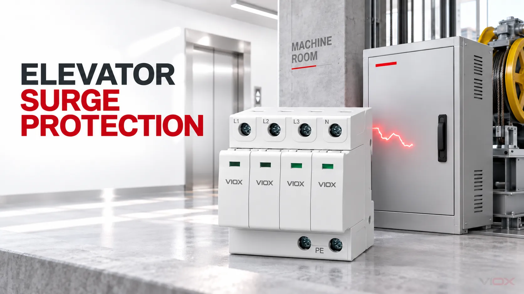
VIOX supplies surge protective device product families for power and selected signal applications. Product selection should follow this evidence schedule; the appearance of a VIOX product in an illustration is not a claim that one model fits every elevator system.
Final Rule
Elevator surge protection is complete only when every relevant conductive boundary has a documented decision.
A defensible design should be able to answer five questions:
- What can carry a surge into or out of this protected zone?
- Which equipment and interface is the SPD intended to protect?
- Are the voltage, protection modes, discharge duty, fault rating, and environmental limits compatible?
- Is the installed SPD coordinated with upstream devices, backup protection, conductor routing, and the equipment withstand objective?
- What commissioning and maintenance evidence proves the protection remains present?
If one answer is missing, the solution is not “choose a larger kA rating.” The solution is to close the missing boundary or evidence gap.