On this page
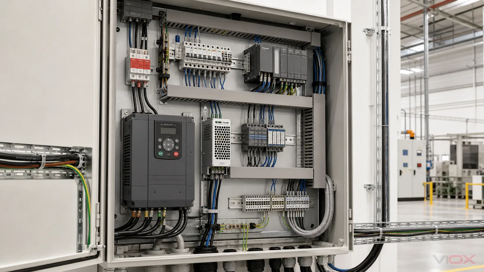
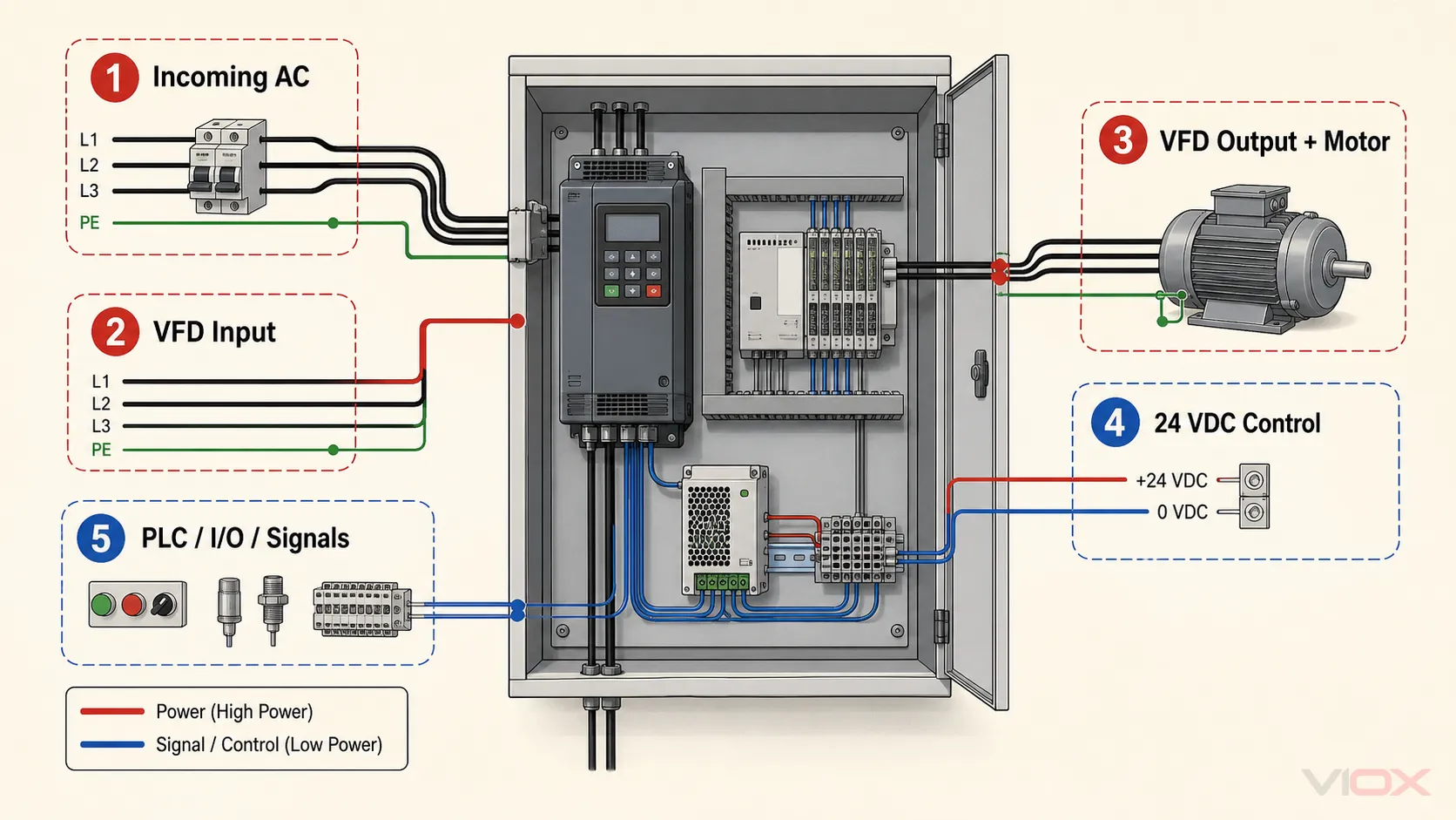
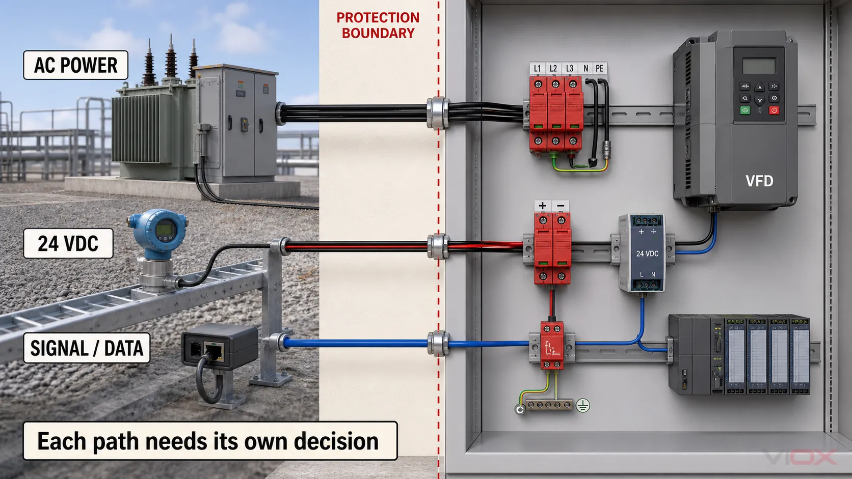
VFD surge protection must be designed around system interfaces, not around one surge protective device (SPD) at the cabinet incomer. Evaluate the incoming AC supply, the variable frequency drive input, the pulse-width-modulated motor output, the 24 VDC control supply, and every exposed control or communication line separately.
A power SPD on the incoming side can limit transients arriving through that power path. It does not automatically protect remote sensors, programmable logic controller (PLC) inputs, RS-485 wiring, Ethernet copper, encoders, or other conductive field circuits. A general-purpose SPD also should not be placed on a VFD output unless the drive and protection-device manufacturers expressly permit that arrangement.
Key Takeaways
- Map five interfaces before selecting products: incoming AC, VFD input, VFD output and motor cable, 24 VDC control power, and PLC/field signal lines.
- Separate external transients from drive-generated output stress: lightning and switching surges entering the panel are not the same phenomenon as repetitive PWM edges, reflected-wave voltage, dv/dt stress, or common-mode current on the motor side.
- Treat every conductive field cable as a possible entry path: power and signal circuits require different SPDs and different compatibility evidence.
- Verify the complete installed path: voltage, protection mode, upstream coordination, conductor routing, bonding, cable shields, signal function, and equipment instructions all affect the result.
Start With the Five-Interface Protection Boundary
The most useful first drawing is not an SPD product diagram. It is a boundary map showing where energy or transient voltage can enter, what equipment is exposed, and which document controls the decision.
| Interface | Main exposure to evaluate | Protection question | Required evidence |
|---|---|---|---|
| Incoming AC supply | Lightning effects, utility switching, contactor or capacitor switching elsewhere in the installation | Is a correctly selected power SPD required at the service, distribution, or VFD-panel node? | System voltage and earthing arrangement, exposure assessment, applicable installation rules, SPD data and coordination evidence |
| VFD input terminals | Residual transient voltage at the drive after upstream protection and wiring impedance | Does the selected cabinet-level protection keep the drive input within its documented immunity and installation conditions? | Exact drive instructions, SPD voltage/protection data, conductor path, upstream/downstream coordination |
| VFD output and motor cable | Repetitive PWM edges, reflected-wave voltage, dv/dt, common-mode current and motor-cable effects | What output reactor, dv/dt filter, sine filter, cable, bonding, or motor-insulation measures does the drive manufacturer require? | Exact drive-and-motor documentation; do not substitute a general-purpose SPD rule |
| 24 VDC control power | Transients coupled through the control-power supply, shared conductors, or external 24 V circuits | Does the DC supply or control bus need a compatible DC protection stage? | Nominal and maximum operating voltage, load current, grounding, protection level, supply and PLC instructions |
| PLC, I/O and communications | Surges induced or conducted on outdoor, long, inter-building, or remote field wiring | Which signal circuits need line-compatible protection at the boundary? | Signal voltage, current, bandwidth, topology, conductor count, grounding/shielding, and equipment documentation |
This map is the page’s central decision tool. If a conductive path crosses the protected-zone boundary, it needs an explicit decision. “Protected by the cabinet SPD” is not an acceptable assumption.
VFD Input and Output Are Different Electrical Environments
The incoming side of a VFD is connected to the power system. External transient overvoltages can arrive through that supply, so power-side SPD selection and coordination are relevant there. IEC 61643-12 describes selection, location, operation, and coordination principles for SPDs connected to low-voltage AC power circuits.
The VFD output is produced by a semiconductor converter and contains repetitive PWM switching edges. Motor-cable length, cable construction, grounding and bonding, motor insulation, switching frequency, and the drive manufacturer’s permitted output components all affect terminal stress. These are power-drive-system questions, not simply another incoming-surge location.
One manufacturer example makes the boundary clear: a Yaskawa FP605 technical reference instructs users not to connect a surge protective device to the drive output side. That statement is not a universal rule for every drive; it demonstrates why an output-side decision must come from the exact drive instructions rather than a generic SPD article.
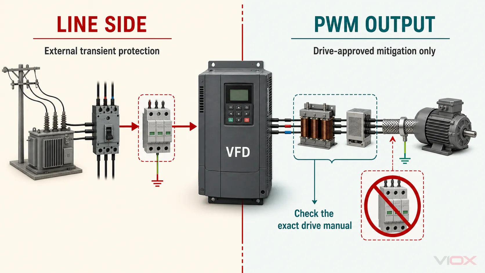
Use this decision rule:
| Location | Default engineering treatment | Stop condition |
|---|---|---|
| Incoming side of the VFD or control panel | Evaluate a power SPD as part of the upstream protection architecture | Stop if system voltage, topology, fault-current coordination, or manufacturer conditions are unknown |
| Between VFD and motor | Use only components and arrangements approved for the exact drive/motor system | Do not improvise an SPD connection from a generic diagram |
| Control and communication terminals | Evaluate each external conductive line as a signal/control interface | Stop if signal voltage, current, bandwidth, grounding, or wiring topology is unknown |
For a deeper explanation of upstream/downstream node verification, use the VIOX SPD coordination and cascading guide.
Build the Power-Side Protection Around Nodes
A facility can have several relevant protection nodes: the service entrance, main distribution, motor-control center, local VFD panel, and equipment area. The correct design is not automatically “one SPD at every panel.” Each node must have a defined protected load, exposure, voltage system, protection mode, and relationship to adjacent stages.
At the VFD panel, record at least:
- AC system voltage and frequency;
- earthing arrangement and the protection modes required by that arrangement;
- whether the supply exposure or lightning-protection concept changes the SPD duty;
- VFD input immunity and installation instructions;
- SPD Uc or MCOV, Up, Type or test class, In/Imax/Iimp where applicable, and declared short-circuit/backup-protection conditions;
- upstream and downstream SPD models and the manufacturer’s coordination evidence;
- conductor length, routing, loop geometry, protective-earth connection, and enclosure layout.
Do not select an SPD from one kA number. The SPD datasheet guide explains how the declarations fit together, while the MCOV guide and TOV guide separate continuous-voltage suitability from temporary overvoltage behavior.
Treat 24 VDC Control Power as Its Own Interface
The PLC, human-machine interface, remote I/O, sensors, relays, and communication equipment may continue to be exposed even when the incoming AC side is protected. A transient can enter through an external 24 VDC circuit, cross a power-supply boundary within its coupling limits, or be induced on field wiring.
Do not choose a DC control-line SPD from the “24 V” label alone. Verify:
- maximum normal operating voltage and polarity;
- line-to-line and line-to-earth protection modes;
- continuous load current when the protector is installed in series;
- voltage protection level under the declared test conditions;
- grounding or shield relationship;
- failure behavior and status indication;
- effect on the safety or availability function of the circuit.
Siemens documentation for specific S7-1200 fail-safe modules provides a useful bounded example: it identifies external surge-protection devices for 24 VDC power, Industrial Ethernet, digital I/O, sensor supply, analog I/O, and AC supply paths. The exact listed devices apply to that documented system, but the wider lesson is transferable: power, control, and signal interfaces are assessed separately.
Protect PLC, Sensor and Communication Paths by Signal Function
An AC power SPD is not connected in the signal path and cannot clamp a transient that arrives through a remote sensor or communication cable before that transient reaches the PLC interface.
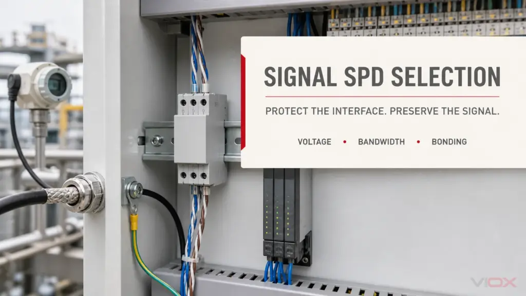
IEC 61643-21 covers SPDs connected to telecommunications and signalling networks, including networks that carry power on the same line. For an industrial control panel, the selection process begins with the actual interface—not with a generic “signal SPD” label.
| Circuit | Inputs that must be documented | Common compatibility risk |
|---|---|---|
| 4–20 mA analog loop | Maximum loop voltage/current, grounding, shield, measurement accuracy | Added series impedance or leakage changes the signal |
| 24 V digital I/O | Input/output type, current, common reference, switching behavior | Protector voltage or current limits do not match the I/O channel |
| RS-485 or Modbus RTU | Differential voltage, common-mode range, topology, data rate, conductor count | Excess capacitance or incorrect grounding degrades communication |
| Industrial Ethernet copper | Category, data rate, Power over Ethernet if present, shield arrangement | Protector is not compatible with bandwidth or powering method |
| Encoder or high-speed pulse line | Signal amplitude, frequency, line driver, reference, cable shield | Capacitance and insertion effects distort the waveform |
| Remote sensor cable | Sensor supply, signal type, cable route, outdoor/inter-building exposure | Protection is installed at only one end of a boundary that needs coordinated treatment |
Use the VIOX signal surge protector selection guide for the full voltage, current, bandwidth, topology, grounding, and documentation workflow.
Bonding, Shields and Routing Complete the Protection Boundary
An SPD is part of a current path. Its installed protection is affected by the path from the exposed conductor through the SPD and bonding system—not only by the value printed on the module.
For the VFD cabinet and connected equipment, verify:
- a defined protective-bonding path between cabinet, mounting plate, equipment and incoming protective conductor;
- drive-manufacturer shield termination and motor-cable instructions;
- physical separation and routing appropriate to power, motor-output, control and communication circuits;
- short, direct SPD connection geometry within the limits of the product instructions;
- field-cable entry points aligned with the selected signal-protection boundary;
- no unintended bypass path around the SPD through parallel wiring, shields or remote earth references.
The VIOX SPD wiring guide covers power-side conductor and backup-protection checks. Exact VFD cable, shield, grounding and EMC practices remain controlled by the drive manufacturer’s instructions and the project EMC design. IEC 61800-3 defines EMC requirements and test methods for adjustable-speed power drive systems, but it is not a substitute for the exact installation manual.
Convert the Architecture Into a Verifiable Specification
Complete one row for every interface before approving a product or panel drawing.
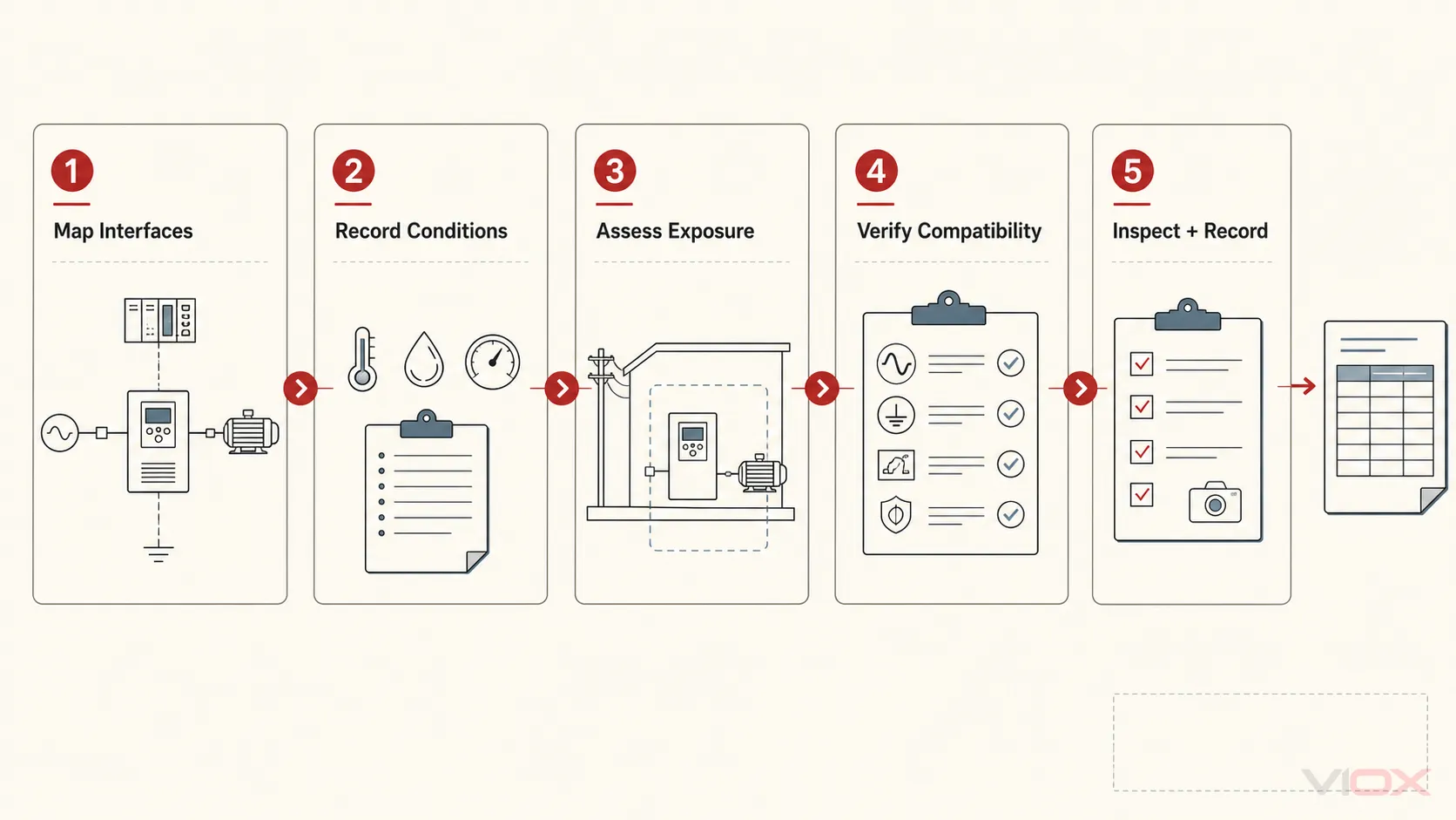
| Interface ID | Circuit and protected equipment | Normal electrical conditions | Transient exposure and boundary | Required SPD/function | Evidence required | Verification record |
|---|---|---|---|---|---|---|
| AC-01 | Panel incomer and VFD input | Voltage, frequency, topology | Upstream supply and panel node | Power SPD if required by design | SPD data, drive instructions, coordination and installation rules | Model, protection modes, conductor route, inspection result |
| DC-01 | 24 VDC control bus | Voltage range, current, grounding | Supply and external DC field circuits | Compatible DC protection where required | Supply/PLC instructions and protector data | Polarity, current path, status, restoration check |
| SIG-01 | PLC or remote field interface | Signal voltage, current, bandwidth, topology | Cable boundary and remote equipment | Compatible signal SPD where required | Interface and protector datasheets | Channel mapping, shield/bonding, functional test |
| MOT-01 | VFD output and motor cable | PWM output, cable and motor data | Drive-generated stress and external cable exposure | Drive-approved output mitigation only | Exact drive/motor instructions | Approved component and commissioning record |
| BOND-01 | Cabinet and cable bonding system | PE, shields, reference conductors | Surge-current return and coupling paths | Bonding/routing measures | Project drawings and equipment instructions | Visual inspection and as-built record |
This worksheet prevents three common specification failures: one device being assigned to every path, an output-side component being selected without drive approval, and a signal protector being chosen without interface compatibility.
Commission and Recheck the Complete System
Before energization, confirm that installed model numbers match the approved documents, plug-in modules are seated, status and remote contacts agree with their documented truth table, and every power or signal connection follows the applicable instructions. Record the final conductor paths, shield terminations, protective bonding, and upstream protective device.
Functional checks must be appropriate to the circuit. An ordinary multimeter cannot reproduce standardized impulse tests or prove the remaining surge capability of an SPD. For communication and I/O circuits, verify normal operation without treating a successful functional test as proof of surge performance.
After a significant event, unexplained drive failure, repeated SPD alarm, or control-system disturbance, do not replace components blindly. Preserve event and alarm records, inspect every interface, and determine whether the evidence points to an incoming transient, temporary overvoltage, wiring/bonding problem, motor-output stress, field-line entry, environmental damage, or another failure mechanism.
Final Design Rule
A VFD panel is protected only when every relevant conductive interface has an explicit, documented decision. Start at the incoming AC node, keep the PWM output under drive-manufacturer control, assess 24 VDC and each exposed signal line separately, and verify the bonding and coordination paths that make the devices work as a system.
For project-level SPD evaluation, review the VIOX surge protective device range and send the single-line diagram, AC and DC voltages, earthing arrangement, VFD model, motor-cable information, I/O and communication schedule, exposure conditions, target market, and required documentation to [email protected].
Sources
- IEC 61643-12:2020 — Low-voltage SPDs connected to AC power systems: selection and application principles
- IEC 61643-21:2025 — SPDs for telecommunications and signalling networks
- IEC 61800-3:2022 — EMC requirements and test methods for adjustable-speed power drive systems
- Siemens S7-1200 fail-safe modules — surge-immunity and external-protection examples
- Yaskawa FP605 technical reference — manufacturer-specific output-side restriction
This article defines an engineering review framework, not construction instructions for a specific panel. Follow the exact VFD, motor, PLC, SPD and signal-protection documentation, the project risk assessment, and the electrical rules applicable to the installation. Work inside industrial control equipment should be performed only by qualified personnel under an approved safe-work procedure.