ໃນໜ້ານີ້
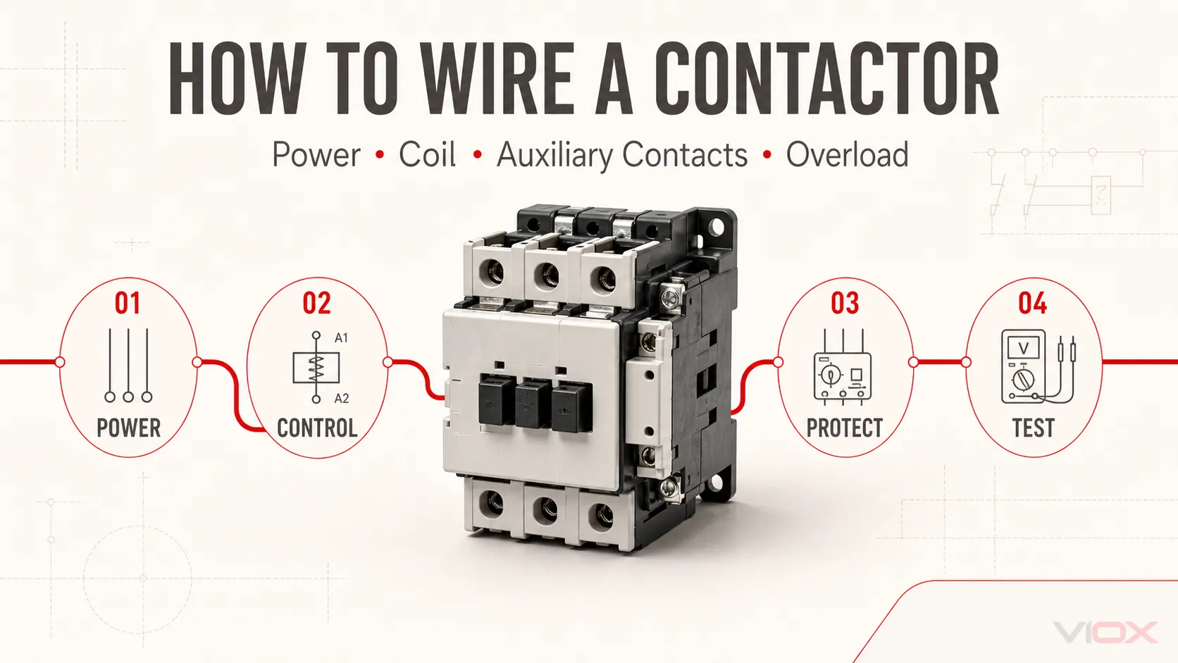
ໃນການຕໍ່ສາຍຄອນແທັກເຕີ, ໃຫ້ເຊື່ອມຕໍ່ວົງຈອນໄຟຟ້າຂາເຂົ້າເຂົ້າກັບຂົ້ວຕໍ່ທີ່ຜູ້ຜະລິດລະບຸວ່າເປັນດ້ານແຫຼ່ງຈ່າຍ, ເຊື່ອມຕໍ່ຂົ້ວຕໍ່ດ້ານໂຫຼດທີ່ສອດຄ້ອງກັນເຂົ້າກັບໂຫຼດ, ແລະ ຈ່າຍໄຟໃຫ້ຄອນແທັກເຕີຄອຍຜ່ານ A1 ແລະ A2 ໂດຍໃຊ້ແຮງດັນຄວບຄຸມທີ່ຖືກຕ້ອງ. ສຳລັບສະຕາດເຕີມໍເຕີ, ໄຟຟ້າຂອງມໍເຕີໂດຍປົກກະຕິຈະຜ່ານຣີເລໂຫຼດເກີນ, ໃນຂະນະທີ່ໜ້າສຳຜັດຕັດວົງຈອນແບບປິດປົກກະຕິຂອງຣີເລໂຫຼດເກີນຈະຖືກຕໍ່ເຂົ້າກັບວົງຈອນຄວບຄຸມຄອຍ.
ນັ້ນແມ່ນເສັ້ນທາງພື້ນຖານ, ແຕ່ເຄື່ອງໝາຍ, ທິດທາງການຈ່າຍໄຟທີ່ອະນຸຍາດ, ປະເພດຄອຍ, ແຮງດັນຄວບຄຸມ, ແລະ ການເຊື່ອມຕໍ່ອຸປະກອນເສີມອາດຈະແຕກຕ່າງກັນ. ໃຫ້ໃຊ້ແຜນວາດການຕໍ່ສາຍທີ່ພິມໄວ້ເທິງອຸປະກອນ ແລະ ແຜ່ນຂໍ້ມູນສຳລັບຮຸ່ນຄອນແທັກເຕີທີ່ແນ່ນອນສະເໝີ.
ຄວາມປອດໄພທາງໄຟຟ້າ: ວົງຈອນຄອນແທັກເຕີອາດມີແຫຼ່ງຈ່າຍໄຟຫຼາຍແຫຼ່ງ ແລະ ແຮງດັນທີ່ເປັນອັນຕະລາຍ. ການຕິດຕັ້ງ, ການທົດສອບ, ແລະ ການນຳໃຊ້ຄວນດຳເນີນການໂດຍບຸກຄະລາກອນໄຟຟ້າທີ່ມີຄຸນວຸດທິເທົ່ານັ້ນ ໂດຍໃຊ້ຂັ້ນຕອນການລັອກ/ແທັກ (lockout/tagout) ທີ່ກ່ຽວຂ້ອງ, ວິທີການທົດສອບແຮງດັນ, ອຸປະກອນປ້ອງກັນສ່ວນບຸກຄົນ, ຄຳແນະນຳຂອງຜູ້ຜະລິດ, ແລະ ກົດລະບຽບໄຟຟ້າທ້ອງຖິ່ນ. ຢ່າຖືວ່າຄຳແນະນຳທົ່ວໄປນີ້ເປັນສິ່ງທົດແທນແຜນວາດໂຄງການ ຫຼື ເອກະສານຜະລິດຕະພັນ.
Key Takeaways
- ຮັກສາວົງຈອນໄຟຟ້າ ແລະ ວົງຈອນຄວບຄຸມໃຫ້ແຍກອອກຈາກກັນທັງໃນແຜນວາດ ແລະ ໃນຕູ້ຄວບຄຸມ.
- L1/L2/L3 ແລະ T1/T2/T3 ແມ່ນເຄື່ອງໝາຍວົງຈອນຫຼັກທີ່ພົບເຫັນທົ່ວໄປ; A1 ແລະ A2 ລະບຸວົງຈອນຄອຍ.
- ຄ່າພິກັດຂອງຄອຍຕ້ອງກົງກັບແຫຼ່ງຈ່າຍຄວບຄຸມ, ບໍ່ແມ່ນແຮງດັນຂອງມໍເຕີ ຫຼື ໂຫຼດ.
- A2 ບໍ່ໄດ້ເຊື່ອມຕໍ່ກັບສາຍນິວທຣອນສະເໝີໄປ. ການເຊື່ອມຕໍ່ຂອງມັນຂຶ້ນຢູ່ກັບແຫຼ່ງຈ່າຍໄຟຄວບຄຸມ ແລະ ການອອກແບບຄອຍ.
- ຄອນແທັກເຕີເຮັດໜ້າທີ່ໃນການສະຫຼັບວົງຈອນ ບໍ່ແມ່ນການປ້ອງກັນໂຫຼດເກີນ ຫຼື ວົງຈອນສັ້ນຢ່າງສົມບູນ.
- ວົງຈອນ START/STOP ແບບສາມສາຍຕ້ອງການຄອນແທັກຊ່ວຍແບບເປີດປົກກະຕິເພື່ອຮັກສາສະຖານະ; ລາຍລະອຽດການຕໍ່ສາຍ ແລະ ການທົດສອບລະບົບທັງໝົດຕ້ອງປະຕິບັດຕາມຮຸ່ນ ແລະ ຂັ້ນຕອນຂອງໂຄງການຢ່າງເຄັ່ງຄັດ.
ແຜນວາດການຕໍ່ສາຍຄອນແທັກເຕີ: ພາບລວມຂອງວົງຈອນທີ່ສົມບູນ
ຊຸດສະຕາດເຕີມໍເຕີສາມເຟສພື້ນຖານປະກອບດ້ວຍສອງວົງຈອນທີ່ກ່ຽວຂ້ອງກັນ:
- ວົງຈອນກຳລັງ (Power circuit): ນຳກະແສໄຟຟ້າມໍເຕີຜ່ານອຸປະກອນປ້ອງກັນວົງຈອນສັ້ນ, ຄອນແທັກເຕີ, ຣີເລໂຫຼດເກີນ ແລະ ມໍເຕີ.
- ວົງຈອນຄວບຄຸມ (Control circuit): ຈ່າຍໄຟໃຫ້ຄອຍຂອງຄອນແທັກເຕີຜ່ານປຸ່ມ STOP, ຄອນແທັກຕັດວົງຈອນເມື່ອໂຫຼດເກີນ, ປຸ່ມ START ແລະ ຄອນແທັກຮັກສາສະຖານະ.
ແຜນວາດການເຮັດວຽກຕໍ່ໄປນີ້ສະແດງໃຫ້ເຫັນເຖິງຄວາມສຳພັນ. ມັນບໍ່ແມ່ນແບບແຕ່ງສ້າງສະເພາະຮຸ່ນ.
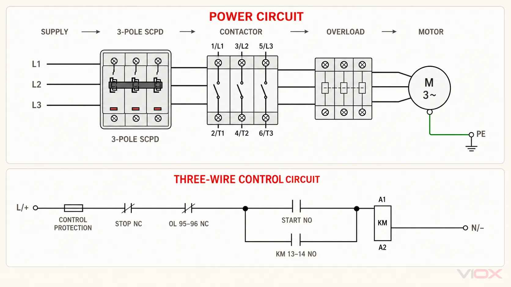
ວົງຈອນກຳລັງ

ການສະໜອງ       ຊຸດ SCPD 3-pole ຫຼື ຟິວທີ່ປະສານງານກັນ     ຄອນແທັກເຕີ      ໂຫຼດເກີນ       ມໍເຕີ
L1  --------[ pole 1                              ]--- 1/L1  2/T1 --- power pole --- U
L2  --------[ pole 2 — ອຸປະກອນ/ຊຸດທີ່ປະສານງານກັນ ]--- 3/L2  4/T2 --- power pole --- V
L3  --------[ pole 3                              ]--- 5/L3  6/T3 --- power pole --- W
PE  ------------------------------------------------------------------------- Frame


ວົງຈອນຄວບຄຸມສາມສາຍ

Control L/+ -- ການປ້ອງກັນວົງຈອນຄວບຄຸມ -- STOP NC -- OL 95-96 NC --+-- START NO --+-- A1
                                                              |              |
                                                              +-- KM 13-14 --+
                                                                             A2 -- N/-
ໃນແຜນວາດການຄວບຄຸມ, KM ລະບຸເຖິງຄອນແທັກເຕີ. ເມື່ອກົດປຸ່ມ START, ຄອຍຈະມີໄຟ. ຈາກນັ້ນໜ້າສຳຜັດຊ່ວຍແບບເປີດປົກກະຕິ 13-14 ຂອງຄອນແທັກເຕີຈະປິດ ແລະ ບາຍພາດປຸ່ມ START ທີ່ຖືກປ່ອຍ. ການກົດປຸ່ມ STOP ຫຼື ການຕັດວົງຈອນຂອງຣີເລໂຫຼດເກີນຈະເຮັດໃຫ້ວົງຈອນຄວບຄຸມເປີດອອກ ແລະ ປ່ອຍຄອນແທັກເຕີ.
ລະບຸຂົ້ວຕໍ່ຄອນແທັກເຕີກ່ອນການຕໍ່ສາຍ
ການກຳນົດຂົ້ວຕໍ່ແບບ IEC ຖືກນຳໃຊ້ຢ່າງກວ້າງຂວາງ, ແຕ່ຕຳແໜ່ງທາງກາຍະພາບ ແລະ ໜ້າສຳຜັດທີ່ມີໃຫ້ຈະແຕກຕ່າງກັນໄປຕາມແຕ່ລະຜະລິດຕະພັນ. ຄອນແທັກເຕີບາງລຸ້ນມີໜ້າສຳຜັດຊ່ວຍໃນຕົວ; ບາງລຸ້ນຕ້ອງການບລັອກເສີມ. ບາງລຸ້ນມີຂົ້ວຕໍ່ຄອຍຊ້ຳກັນເພື່ອເຮັດໃຫ້ການຕໍ່ສາຍໃນຕູ້ຄວບຄຸມງ່າຍຂຶ້ນ.
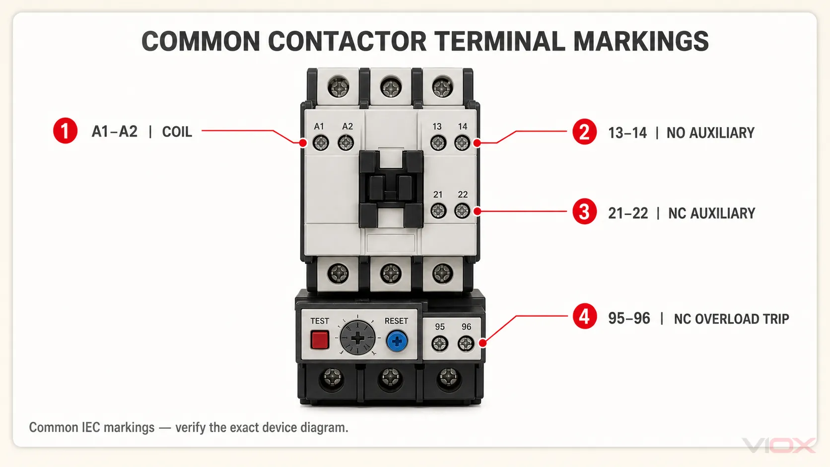
| ການໝາຍແບບທົ່ວໄປ | ໜ້າທີ່ການເຮັດວຽກທົ່ວໄປ | ສິ່ງທີ່ຕ້ອງກວດສອບ |
|---|---|---|
| 1/L1, 3/L2, 5/L3 | ຕົວນຳວົງຈອນຫຼັກຂາເຂົ້າ | ທິດທາງການສະໜອງໄຟ ແລະ ການຈັດລຽງເຟສທີ່ອະນຸຍາດ |
| 2/T1, 4/T2, 6/T3 | ຜົນຜະລິດທີ່ຜ່ານການສະຫຼັບໄປຫາໂຫຼດ ຫຼື ຣີເລໂຫຼດເກີນ | ການຈັບຄູ່ທີ່ຖືກຕ້ອງກັບຂົ້ວຕໍ່ສາຍທີ່ກ່ຽວຂ້ອງ |
| A1, A2 | ຄອຍຄອນແທັກເຕີ | ແຮງດັນໄຟຟ້າທີ່ກຳນົດ, AC ຫຼື DC, ຄວາມຖີ່ໃນກໍລະນີທີ່ກ່ຽວຂ້ອງ, ແລະ ຂໍ້ກຳນົດດ້ານຂົ້ວ |
| 13-14 | ໜ້າສຳຜັດຊ່ວຍເປີດປົກກະຕິອັນທຳອິດ | ຄວາມພ້ອມໃຊ້ງານ ແລະ ພິກັດຂອງວົງຈອນຄວບຄຸມ |
| 21-22 | ໜ້າສຳຜັດຊ່ວຍແບບປິດປົກກະຕິອັນທຳອິດ | ຄວາມພ້ອມໃຊ້ງານ ແລະ ໜ້າທີ່ໃນການລັອກກັນ (interlock) ຫຼື ການສະແດງຜົນທີ່ກຳນົດໄວ້ |
| 95-96 | ໜ້າສຳຜັດຕັດວົງຈອນເມື່ອໂຫຼດເກີນແບບປິດປົກກະຕິທົ່ວໄປ | ແຜນວາດຣີເລໂຫຼດເກີນທີ່ແນ່ນອນ ແລະ ການຈັດວາງການຣີເຊັດ |
| 97-98 | ໜ້າສຳຜັດຕັດວົງຈອນເມື່ອໂຫຼດເກີນແບບເປີດປົກກະຕິທົ່ວໄປ | ແຜນວາດຣີເລໂຫຼດເກີນທີ່ແນ່ນອນ ແລະ ໜ້າທີ່ການສະແດງຜົນ |
ສົນທິສັນຍາຂົ້ວຕໍ່ຂ້າງເທິງນີ້ໄດ້ຮັບການສະໜັບສະໜູນໂດຍເອກະສານຄອນແທັກເຕີຂອງຜູ້ຜະລິດ, ລວມເຖິງ ຄູ່ມືຄອນແທັກເຕີ ແລະ ຣີເລໂຫຼດເກີນຂອງ ABB. ແນວໃດກໍຕາມ, ການຄຸ້ນເຄີຍກັບໝາຍເລກຂົ້ວຕໍ່ບໍ່ໄດ້ໝາຍຄວາມວ່າທ່ານສາມາດຂ້າມການກວດສອບແຜນວາດຜະລິດຕະພັນທີ່ແນ່ນອນໄດ້.
ສຳລັບຄຳອະທິບາຍທີ່ເນັ້ນໃສ່ຂົ້ວຕໍ່ຫຼັກ, ເບິ່ງ L1, L2, T1, ແລະ T2 ຫມາຍຄວາມວ່າແນວໃດໃນ Contactor?.
ກ່ອນທີ່ທ່ານຈະຕໍ່ສາຍຄອນແທັກເຕີ: ຢືນຢັນ 6 ປັດໄຈນຳເຂົ້າ
ກ່ອນເລີ່ມຕົ້ນ, ໃຫ້ບັນທຶກ 6 ປັດໄຈນຳເຂົ້າທີ່ກຳນົດວົງຈອນຕົວຈິງ.
| ການປ້ອນຂໍ້ມູນ | ຄຳຖາມທີ່ຕ້ອງຕອບ | ເປັນຫຍັງມັນຈຶ່ງປ່ຽນແປງການຕໍ່ສາຍ |
|---|---|---|
| ແຫຼ່ງຈ່າຍໄຟຫຼັກ | ການຈັດລຽງເຟສ, ແຮງດັນໄຟຟ້າ, ແລະ ຄວາມຖີ່ | ຂົ້ວຕໍ່ຫຼັກ ແລະ ອຸປະກອນຕົ້ນທາງ |
| ໂຫຼດ | ມໍເຕີ, ເຄື່ອງເຮັດຄວາມຮ້ອນ, ໄຟເຍືອງທາງ, ຊຸດຄາປາຊິເຕີ, ຫຼື ໂຫຼດອື່ນໆ | ປະເພດການນຳໃຊ້ ແລະ ການປ້ອງກັນ |
| Contactor | ຮຸ່ນ, ການຈັດວາງຂົ້ວ, ແລະ ທິດທາງການເຊື່ອມຕໍ່ທີ່ອະນຸຍາດ | ແຜນຜັງຂົ້ວຕໍ່ທີ່ແນ່ນອນ |
| ມ້ວນ | ແຮງດັນ, ປະເພດ AC/DC, ຄວາມຖີ່, ແລະ ຂົ້ວໄຟຟ້າ | ການສະໜອງໄຟຄວບຄຸມ A1/A2 |
| ວິທີການຄວບຄຸມ | ອຸປະກອນທີ່ຮັກສາສະຖານະ, PLC, ຫຼື ປຸ່ມ START/STOP | ເຫດຜົນແບບສອງສາຍ ຫຼື ສາມສາຍ |
| ການປົກປ້ອງ | ວິທີການປ້ອງກັນວົງຈອນສັ້ນ ແລະ ໂຫຼດເກີນ | ອຸປະກອນທີ່ຕ້ອງການໃຫ້ເຮັດວຽກຮ່ວມກັນ |
ມໍເຕີອາດຈະເຮັດວຽກຢູ່ທີ່ແຮງດັນ 400 V ສາມເຟສ ໃນຂະນະທີ່ຄອຍຂອງຄອນແທັກເຕີເຮັດວຽກດ້ວຍແຮງດັນ 24 V DC, 110 V AC, 120 V AC, 230 V AC, ຫຼື ແຮງດັນຄວບຄຸມອື່ນໆທີ່ລະບຸໄວ້. ຫ້າມຄາດເດົາແຮງດັນຂອງຄອຍຈາກແຮງດັນຂອງໂຫຼດໂດຍເດັດຂາດ.
ຖ້າຫາກຍັງບໍ່ໄດ້ເລືອກຄອນແທັກເຕີ, ໃຫ້ໃຊ້ຄູ່ມືແຍກຕ່າງຫາກເພື່ອ ເລືອກຄອນແທັກເຕີ, ຣີເລໂຫຼດເກີນ, ແລະ ເບຣກເກີວົງຈອນ ຈາກຂໍ້ມູນຂອງມໍເຕີ. ບົດຄວາມນີ້ສົມມຸດວ່າການເລືອກອົງປະກອບ ແລະ ການອອກແບບການປ້ອງກັນໄດ້ສຳເລັດແລ້ວ.
ຂັ້ນຕອນທີ 1: ແຍກແຫຼ່ງຈ່າຍໄຟທຸກແຫຼ່ງ ແລະ ກວດສອບໃຫ້ແນ່ໃຈວ່າວົງຈອນບໍ່ມີກະແສໄຟຟ້າແລ້ວ
ຕູ້ຄວບຄຸມອາດມີແຫຼ່ງຈ່າຍໄຟຫຼັກ, ໝໍ້ແປງຄວບຄຸມແຍກຕ່າງຫາກ, ແຫຼ່ງຈ່າຍໄຟ PLC ພາຍນອກ, ຫຼື ສັນຍານທາງໄກທີ່ຍັງມີໄຟລ້ຽງຢູ່ຫຼັງຈາກທີ່ຕັດການເຊື່ອມຕໍ່ຫຼັກແລ້ວ.
ກ່ອນທີ່ຈະສຳຜັດກັບຕົວນຳໄຟຟ້າ, ໃຫ້ລະບຸແຫຼ່ງພະລັງງານທຸກແຫຼ່ງ, ປິດເຄື່ອງ ແລະ ແຍກອຸປະກອນອອກ, ປະຕິບັດຕາມມາດຕະການລັອກ/ຕິດປ້າຍ (lockout/tagout) ທີ່ກຳນົດໄວ້, ແລະ ໃຫ້ຜູ້ທີ່ມີຄວາມຊຳນານກວດສອບສະພາວະທີ່ບໍ່ມີໄຟລ້ຽງດ້ວຍອຸປະກອນທົດສອບທີ່ເໝາະສົມຕາມຂັ້ນຕອນທີ່ໄດ້ຮັບການອະນຸມັດ. ຄຳແນະນຳກ່ຽວກັບຄອນແທັກເຕີຂອງ Schneider Electric ກໍໄດ້ຈຳກັດການຕິດຕັ້ງ ແລະ ການບໍລິການໄວ້ສະເພາະບຸກຄະລາກອນທີ່ມີຄວາມຊຳນານເທົ່ານັ້ນ ແລະ ຮຽກຮ້ອງໃຫ້ຕັດການເຊື່ອມຕໍ່ໄຟຟ້າທັງໝົດກ່ອນການບໍລິການ.
ສຳລັບໂຄງການລະດັບສາກົນ, ໃຫ້ປະຕິບັດຕາມກົດລະບຽບແຫ່ງຊາດ, ຂໍ້ກຳນົດທ້ອງຖິ່ນ, ຂັ້ນຕອນການເຮັດວຽກໃນສະຖານທີ່, ແລະ ຄຳແນະນຳຂອງຜູ້ຜະລິດທີ່ກ່ຽວຂ້ອງ. ສຳລັບການຕິດຕັ້ງໃນສະຫະລັດອາເມຣິກາ, ສະບັບທີ່ນຳໃຊ້ໃນທ້ອງຖິ່ນຂອງ NFPA 70, ມາດຕະຖານໄຟຟ້າແຫ່ງຊາດ (National Electrical Code) ຈະເປັນຕົວຄວບຄຸມຂໍ້ກຳນົດໃນການຕິດຕັ້ງ; NFPA 70E ຈະກ່າວເຖິງການປະຕິບັດງານດ້ານໄຟຟ້າຢ່າງປອດໄພ. ຂໍ້ກຳນົດຂອງ OSHA ອາດຈະນຳໃຊ້ໄດ້ເຊັ່ນກັນ, ລວມເຖິງ 29 CFR 1910.333 ສຳລັບການຕັດໄຟ, ການກວດສອບ, ແລະ ການປະຕິບັດງານຂອງບຸກຄະລາກອນທີ່ມີຄວາມຊຳນານ, ແລະ 29 CFR 1910.147 ບ່ອນທີ່ການບໍລິການ ຫຼື ການບຳລຸງຮັກສາມີຄວາມກ່ຽວຂ້ອງກັບພະລັງງານທີ່ເປັນອັນຕະລາຍ. ການນຳໃຊ້ຂຶ້ນຢູ່ກັບສະຖານທີ່ເຮັດວຽກ ແລະ ວຽກງານທີ່ກ່ຽວຂ້ອງ.
ຂັ້ນຕອນທີ 2: ຕິດຕັ້ງຄອນແທັກເຕີ ແລະ ວາງແຜນເສັ້ນທາງສາຍໄຟ
ຕິດຕັ້ງຄອນແທັກເຕີໃສ່ຮາງ DIN, ແຜ່ນຍຶດ, ຫຼື ຊຸດສະຕາດເຕີທີ່ກຳນົດໄວ້ ໃນທິດທາງທີ່ຜູ້ຜະລິດອະນຸຍາດ. ກວດສອບໃຫ້ແນ່ໃຈວ່າບລັອກອຸປະກອນເສີມ, ຣີເລໂຫຼດເກີນ, ຝາປິດ, ແລະ ສະກູຂົ້ວຕໍ່ຍັງສາມາດເຂົ້າເຖິງໄດ້.
ເດີນສາຍໄຟກຳລັງ ແລະ ສາຍຄວບຄຸມຜ່ານຮາງສາຍໄຟທີ່ກຳນົດໄວ້, ຮັກສາຄວາມຕໍ່ເນື່ອງຂອງສາຍດິນປ້ອງກັນໃຫ້ເປັນອິດສະຫຼະຈາກການເຮັດວຽກຂອງຄອນແທັກເຕີ, ຮັກສາໄລຍະຫ່າງ ແລະ ການລະບາຍອາກາດທີ່ຈຳເປັນ, ແລະ ຮັກສາໝາຍເລກສາຍໄຟໃຫ້ເຫັນໄດ້ຊັດເຈນຢູ່ທີ່ຂົ້ວຕໍ່.
ຢ່າຄາດເດົາວ່າຄອນແທັກເຕີທຸກລຸ້ນຮັບໄຟຈາກດ້ານເທິງເທົ່ານັ້ນ. ບາງກຸ່ມຜະລິດຕະພັນອະນຸຍາດໃຫ້ມີທິດທາງການຈ່າຍໄຟທາງເລືອກພາຍໃຕ້ເງື່ອນໄຂທີ່ກຳນົດໄວ້, ໃນຂະນະທີ່ບາງລຸ້ນມີຂໍ້ກຳນົດສະເພາະຂອງຮຸ່ນ ຫຼື ໃບຢັ້ງຢືນ. ໃຫ້ປະຕິບັດຕາມຂົ້ວຕໍ່ທີ່ມີເຄື່ອງໝາຍ ແລະ ແຜ່ນຂໍ້ມູນການຕິດຕັ້ງ.
ຂັ້ນຕອນທີ 3: ຕໍ່ສາຍວົງຈອນໄຟຟ້າຫຼັກ
ການຕໍ່ສາຍຄອນແທັກເຕີສາມເຟສ
ສຳລັບການຈັດວາງຄອນແທັກເຕີສາມຂົ້ວທົ່ວໄປ:
- ເຊື່ອມຕໍ່ເຟສຂາເຂົ້າທີ່ມີການປ້ອງກັນເຂົ້າກັບຂົ້ວຕໍ່ຂອງຄອນແທັກເຕີທີ່ລະບຸໄວ້ເປັນ 1/L1, 3/L2, ແລະ 5/L3.
- ເຊື່ອມຕໍ່ 2/T1, 4/T2, ແລະ 6/T3 ເຂົ້າກັບອຸປະກອນຖັດໄປໃນເສັ້ນທາງພະລັງງານ.
- ສຳລັບສະຕາດເຕີມໍເຕີທີ່ໃຊ້ຣີເລໂຫຼດເກີນແຍກຕ່າງຫາກ, ໃຫ້ເດີນສາຍຕົວນຳມໍເຕີທີ່ຈຳເປັນທັງໝົດຜ່ານຣີເລໂຫຼດເກີນຕາມແຜນວາດຂອງມັນ.
- ເຊື່ອມຕໍ່ຜົນຜະລິດຂອງຣີເລໂຫຼດເກີນເຂົ້າກັບຂົ້ວຕໍ່ມໍເຕີທີ່ລະບຸໂດຍຜູ້ຜະລິດມໍເຕີ.
- ເຊື່ອມຕໍ່ສາຍດິນປ້ອງກັນເຂົ້າກັບໂຄງມໍເຕີ ແລະ ຈຸດເຊື່ອມຕໍ່ທີ່ຈຳເປັນ. ຫ້າມເດີນສາຍ PE ຜ່ານຂົ້ວຂອງຄອນແທັກເຕີປົກກະຕິ.
ຮັກສາລຳດັບເຟສໃຫ້ສອດຄ່ອງກັນຕະຫຼອດຄອນແທັກເຕີ ແລະ ຣີເລໂຫຼດເກີນ. ການໝູນຂອງມໍເຕີຈະຕ້ອງໄດ້ຮັບການກວດສອບໃນລະຫວ່າງການທົດສອບລະບົບ ເນື່ອງຈາກລຳດັບເຟສຂາເຂົ້າ ແລະ ການເຊື່ອມຕໍ່ມໍເຕີເປັນຕົວການົດທິດທາງຕົວຈິງ.
ການຕໍ່ສາຍຄອນແທັກເຕີເຟສດຽວ
ໂຫຼດເຟສດຽວອາດຈະໃຊ້ຂົ້ວຫຼັກໜຶ່ງຂົ້ວຫຼືຫຼາຍກວ່ານັ້ນ ຂຶ້ນຢູ່ກັບຄອນແທັກເຕີ, ການຈັດວາງລະບົບ, ຂໍ້ກຳນົດການແຍກວົງຈອນ, ແລະ ກົດລະບຽບການເດີນສາຍໄຟໃນທ້ອງຖິ່ນ.
ເສັ້ນທາງພະລັງງານພື້ນຖານແມ່ນ:
ຕົວນຳໄຟຟ້າຂາເຂົ້າທີ່ມີການປ້ອງກັນ -> ຂົ້ວຕໍ່ຫຼັກຂອງຄອນແທັກເຕີ -> ຕົວນຳໄຟຟ້າໄປຫາໂຫຼດການຈະຕັດວົງຈອນສາຍນິວທຣອນ ຫຼື ສາຍທີ່ມີໄຟອີກເສັ້ນໜຶ່ງນຳນັ້ນ ແມ່ນຂຶ້ນກັບການອອກແບບ ບໍ່ແມ່ນກົດເກນທົ່ວໄປຂອງຄອນແທັກເຕີ. ຢ່າຄັດລອກຕົວຢ່າງການໃຊ້ສອງຂົ້ວໂດຍບໍ່ໄດ້ກວດສອບລະບົບໄຟຟ້າ, ຂໍ້ກຳນົດໃນການຕັດວົງຈອນ, ໂຫຼດ ແລະ ຄຳແນະນຳສະເພາະຂອງອຸປະກອນນັ້ນໆ.
ຖ້າໂຄງການນຳໃຊ້ອຸປະກອນທີ່ຕິດຕັ້ງເທິງຮາງ DIN ສຳລັບລະບົບໄຟເຍືອງທາງ, ລະບົບທຳຄວາມຮ້ອນ ຫຼື ລະບົບຄວບຄຸມອາຄານ, ຄູ່ມືການເລືອກ ແລະ ການຕໍ່ສາຍ Modular Contactor ກວມເອົາກຸ່ມຜະລິດຕະພັນທີ່ສະເພາະເຈາະຈົງກວ່ານັ້ນ.
ຂັ້ນຕອນທີ 4: ຕໍ່ສາຍເຂົ້າກັບຂົ້ວຕໍ່ຄອຍ A1 ແລະ A2
ຄອຍແມ່ນອິນພຸດການເຮັດວຽກຂອງຄອນແທັກເຕີ. ການປ້ອນແຮງດັນຄວບຄຸມຕາມພິກັດເຂົ້າໄປທີ່ A1 ແລະ A2 ຈະສ້າງແຮງແມ່ເຫຼັກທີ່ເຮັດໃຫ້ໜ້າສຳຜັດຫຼັກ ແລະ ໜ້າສຳຜັດຊ່ວຍປິດວົງຈອນ. ການຕັດແຮງດັນດັ່ງກ່າວອອກຈະເຮັດໃຫ້ກົນໄກປ່ອຍອອກ.
ປະຕິບັດຕາມລຳດັບນີ້:
- ອ່ານປ້າຍກຳກັບຄອຍ ແລະ ລະຫັດສິນຄ້າ.
- ຢືນຢັນແຮງດັນໄຟຟ້າຂອງຄອຍທີ່ກຳນົດໄວ້.
- ຢືນຢັນວ່າຄອຍເປັນປະເພດ AC ຫຼື DC.
- ສຳລັບຄອຍ AC, ໃຫ້ຢືນຢັນຄວາມຖີ່ທີ່ລະບຸໄວ້ໃນກໍລະນີທີ່ກ່ຽວຂ້ອງ.
- ສຳລັບຄອຍ DC, ໃຫ້ກວດສອບວ່າຂົ້ວໄຟຟ້າຖືກໝາຍໄວ້ ຫຼື ຖືກກຳນົດໂດຍຄອຍອີເລັກໂທຣນິກ ຫຼື ໂມດູນປ້ອງກັນກະແສເກີນ.
- ລະບຸຕົວນຳສອງເສັ້ນຂອງແຫຼ່ງຈ່າຍໄຟຄວບຄຸມຕົວຈິງ.
- ເດີນສາຍວົງຈອນຄວບຄຸມທີ່ຜ່ານສະວິດໄປຍັງ A1 ແລະ ເສັ້ນທາງກັບທີ່ກຳນົດໄວ້ໄປຍັງ A2, ເວັ້ນເສຍແຕ່ວ່າແຜນວາດຂອງຜະລິດຕະພັນຈະລະບຸການຈັດວາງທີ່ແຕກຕ່າງອອກໄປ.
ຕົວນຳກັບທີ່ A2 ຖືກກຳນົດໂດຍແຫຼ່ງຈ່າຍໄຟຄວບຄຸມ ບໍ່ແມ່ນໂດຍປ້າຍກຳກັບຂົ້ວຕໍ່ພຽງຢ່າງດຽວ. ຕົວຢ່າງເຊັ່ນ: ໃນລະບົບໄຟຟ້າ 220/380 V, ຄອຍ AC 220 V ທີ່ໄດ້ມາດຕະຖານອາດຈະໃຊ້ແຫຼ່ງຈ່າຍໄຟແບບ Line-to-Neutral, ໃນຂະນະທີ່ຄອຍ AC 380 V ທີ່ໄດ້ມາດຕະຖານອາດຈະໃຊ້ແຫຼ່ງຈ່າຍໄຟແບບ Line-to-Line. ເຫຼົ່ານີ້ເປັນພຽງຕົວຢ່າງຂອງວົງຈອນຄວບຄຸມເທົ່ານັ້ນ: ແຮງດັນໄຟຟ້າທີ່ກຳນົດຕົວຈິງ, ການປ້ອງກັນວົງຈອນຄວບຄຸມ, ວິທີການເດີນສາຍໄຟ, ແລະ ການເຊື່ອມຕໍ່ A1/A2 ຕ້ອງປະຕິບັດຕາມປ້າຍຊື່ຂອງຄອຍ, ແຜນວາດທີ່ແນ່ນອນຂອງຜູ້ຜະລິດ ແລະ ກົດລະບຽບທ້ອງຖິ່ນທີ່ກ່ຽວຂ້ອງ.
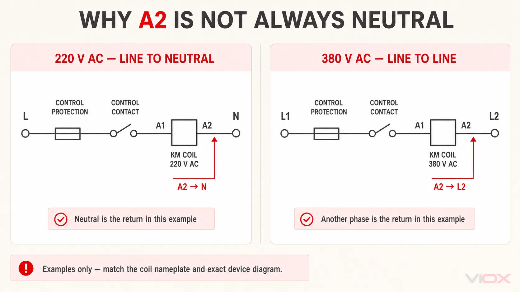
A2 ຕ້ອງເຊື່ອມຕໍ່ກັບສາຍ N ສະເໝີໄປບໍ?
ບໍ່. A2 ເຊື່ອມຕໍ່ກັບດ້ານກັບຂອງວົງຈອນຄອຍ. ເຊິ່ງອາດຈະເປັນສາຍ N, ເຟສອື່ນ, 0 V DC, ຫຼືສາຍຄວບຄຸມອື່ນທີ່ກຳນົດໄວ້, ຂຶ້ນຢູ່ກັບແຫຼ່ງຈ່າຍໄຟຄວບຄຸມ.
ຕົວຢ່າງປະກອບມີ:
- ການຄວບຄຸມ AC ແບບເຟສຫາສາຍ N;
- ການຄວບຄຸມ AC ແບບເຟສຫາເຟສ;
- ດ້ານທຸຕິຍະພູມຂອງໝໍ້ແປງຄວບຄຸມທີ່ແຍກອອກມາຕ່າງຫາກ;
- ແຫຼ່ງຈ່າຍໄຟຄວບຄຸມ 24 V DC;
- ໂມດູນຄວບຄຸມອີເລັກໂທຣນິກທີ່ກຳນົດໂດຍຜູ້ຜະລິດຄອນແທັກເຕີ.
ຢ່າເຊື່ອມຕໍ່ສາຍ N ເຂົ້າກັບ A2 ພຽງເພາະວ່າແຜນວາດທົ່ວໄປສະແດງໄວ້ແບບນັ້ນ. ໃຫ້ກວດສອບແຫຼ່ງຈ່າຍໄຟຄວບຄຸມ ແລະ ພິກັດຂອງຄອຍກ່ອນ.
ຂັ້ນຕອນທີ 5: ເລືອກການຄວບຄຸມແບບສອງສາຍ ຫຼື ສາມສາຍ
ວິທີການຄວບຄຸມຈະເປັນຕົວ ກຳນົດສິ່ງທີ່ຈະເກີດຂຶ້ນເມື່ອສັນຍານຄວບຄຸມ ຫຼື ແຫຼ່ງຈ່າຍໄຟຖືກຕັດຂາດ.
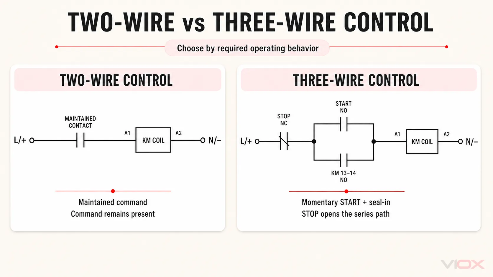
| ວິທີການຄວບຄຸມ | ອຸປະກອນຄວບຄຸມທົ່ວໄປ | ຕ້ອງການຄອນແທັກຮັກສາສະຖານະ (Holding contact) ບໍ່? | ພຶດຕິກຳທົ່ວໄປ |
|---|---|---|---|
| ການຄວບຄຸມແບບສອງສາຍ | ສະວິດເລືອກແບບຮັກສາສະຖານະ, ເທີໂມສະແຕດ, ສະວິດລູກລອຍ, ສະວິດຄວາມດັນ, ຣີເລ, ຫຼື ຄຳສັ່ງ PLC ແບບຮັກສາສະຖານະ | ບໍ່ | ຄອນແທັກເຕີເຮັດວຽກຕາມຄຳສັ່ງທີ່ຮັກສາສະຖານະໄວ້ |
| ການຄວບຄຸມແບບສາມສາຍ | ປຸ່ມກົດ STOP ແລະ START ແບບຊົ່ວຄາວ | ແມ່ນແລ້ວ | ຄອນແທັກເຕີຍັງຄົງມີໄຟລ້ຽງຜ່ານໜ້າສຳຜັດຊ່ວຍ ຈົນກວ່າປຸ່ມ STOP, ການຕັດວົງຈອນເມື່ອໂຫຼດເກີນ, ຫຼື ໄຟຟ້າດັບຈະເຮັດໃຫ້ວົງຈອນເປີດອອກ |
ການຄວບຄຸມຄອນແທັກເຕີແບບສອງສາຍພື້ນຖານ
ເສັ້ນທາງການຄວບຄຸມທີ່ງ່າຍທີ່ສຸດແມ່ນ:
ແຫຼ່ງຈ່າຍໄຟຄວບຄຸມ -> ອຸປະກອນປ້ອງກັນວົງຈອນຄວບຄຸມ -> ໜ້າສຳຜັດຄວບຄຸມແບບຄົງທີ່ -> A1
A2 -> ສາຍກັບຂອງວົງຈອນຄວບຄຸມ
ເມື່ອໜ້າສຳຜັດແບບຄົງທີ່ປິດ, ຄອຍຈະມີໄຟລ້ຽງ. ເມື່ອມັນເປີດ, ຄອຍຈະປ່ອຍ. ເນື່ອງຈາກຄຳສັ່ງຄວບຄຸມຍັງຄົງຢູ່, ລະບົບສອງສາຍບາງລະບົບສາມາດເລີ່ມຕົ້ນໃໝ່ໄດ້ເມື່ອໄຟຟ້າຄວບຄຸມກັບມາ. ໃຫ້ພິຈາລະນາວ່າພຶດຕິກຳດັ່ງກ່າວສາມາດຍອມຮັບໄດ້ສຳລັບເຄື່ອງຈັກ ຫຼື ຂະບວນການນັ້ນຫຼືບໍ່ ກ່ອນທີ່ຈະເລືອກວົງຈອນດັ່ງກ່າວ.
ການຄວບຄຸມ START/STOP ແບບສາມສາຍ
ວົງຈອນສາມສາຍໃຊ້ປຸ່ມຢຸດ (STOP) ແບບປິດປົກກະຕິ, ປຸ່ມເລີ່ມ (START) ແບບເປີດປົກກະຕິ, ແລະໜ້າສຳຜັດຊ່ວຍຂອງຄອນແທັກເຕີແບບເປີດປົກກະຕິ.
L/+ -- STOP NC -- OL 95-96 NC --+-- START NO --+-- A1
                                 |              |
                                 +-- KM 13-14 --+
                                                A2 -- N/-
ການດໍາເນີນງານ:
- ເມື່ອປຸ່ມ STOP ແລະໜ້າສຳຜັດໂຫຼດເກີນປິດຢູ່, ການກົດປຸ່ມ START ຈະເຮັດໃຫ້ຄອຍມີໄຟ.
- ຄອນແທັກເຕີຈະປິດໜ້າສຳຜັດຫຼັກ ແລະໜ້າສຳຜັດຊ່ວຍ 13-14.
- ໜ້າສຳຜັດ 13-14 ທີ່ປິດຢູ່ຈະສ້າງເສັ້ນທາງຂະໜານອ້ອມປຸ່ມ START.
- ການປ່ອຍປຸ່ມ START ຈະບໍ່ຕັດວົງຈອນຄອຍອີກຕໍ່ໄປ.
- ການກົດປຸ່ມ STOP ຈະເປີດເສັ້ນທາງຄວບຄຸມແບບອະນຸກົມ ແລະປ່ອຍຄອນແທັກເຕີ.
- ການຕັດວົງຈອນເນື່ອງຈາກໂຫຼດເກີນຈະເປີດໜ້າສຳຜັດ 95-96 ແລະປ່ອຍຄອນແທັກເຕີເຊັ່ນກັນ.
- ການສູນເສຍໄຟລ້ຽງວົງຈອນຄວບຄຸມຈະເຮັດໃຫ້ຄອນແທັກເຕີປ່ອຍ; ໂດຍປົກກະຕິແລ້ວຈະຕ້ອງມີຄຳສັ່ງ START ໃໝ່ຫຼັງຈາກໄຟກັບມາເປັນປົກກະຕິ.
ຖ້າຄອນແທັກເຕີດຶງຕົວສະເພາະໃນຂະນະທີ່ກົດປຸ່ມ START ຄ້າງໄວ້, ໃຫ້ກວດສອບຄອນແທັກຮັກສາສະຖານະ (holding contact), ການກຳນົດຂົ້ວຕໍ່ຂອງມັນ, ແລະ ການຕໍ່ສາຍຂະໜານອ້ອມປຸ່ມ START.
ຂັ້ນຕອນທີ 6: ເຊື່ອມຕໍ່ຣີເລໂຫຼດເກີນສຳລັບຊຸດສະຕາດເຕີມໍເຕີ
ຄອນແທັກເຕີເປັນອຸປະກອນສະຫຼັບໄຟຟ້າ. ໂດຍປົກກະຕິແລ້ວມັນບໍ່ໄດ້ໃຫ້ການປ້ອງກັນໂຫຼດເກີນຂອງມໍເຕີ ຫຼື ການຕັດວົງຈອນສັ້ນດ້ວຍຕົວມັນເອງ. ຊຸດສະຕາດເຕີມໍເຕີພື້ນຖານໂດຍທົ່ວໄປຈະລວມເອົາຄອນແທັກເຕີເຂົ້າກັບຣີເລໂຫຼດເກີນ ແລະ ສາຍໄຟຄວບຄຸມທີ່ຈຳເປັນ. ຄວາມແຕກຕ່າງໄດ້ຖືກອະທິບາຍໄວ້ໃນ ຄອນແທັກເຕີທຽບກັບເຄື່ອງເລີ່ມຕົ້ນມໍເຕີ.
ສຳລັບການຈັດວາງແບບຣີເລໂຫຼດເກີນແຍກຕ່າງຫາກທົ່ວໄປ:
- ເຊື່ອມຕໍ່ຂົ້ວຕໍ່ຜົນອອກດ້ານໂຫຼດຂອງຄອນແທັກເຕີເຂົ້າກັບຂົ້ວຕໍ່ໄຟເຂົ້າຂອງຣີເລໂຫຼດເກີນ ຕາມທີ່ຜູ້ຜະລິດໄດ້ສະແດງໄວ້.
- ເຊື່ອມຕໍ່ຂົ້ວຕໍ່ຜົນອອກດ້ານໄຟຟ້າຂອງຣີເລໂຫຼດເກີນເຂົ້າກັບມໍເຕີ.
- ວາງຄອນແທັກຕັດວົງຈອນແບບປິດປົກກະຕິຂອງຣີເລໂຫຼດເກີນ, ເຊິ່ງໂດຍທົ່ວໄປແມ່ນ 95-96, ໄວ້ໃນວົງຈອນອະນຸກົມກັບຄອຍຂອງຄອນແທັກເຕີ.
- ໃຊ້ຂົ້ວຕໍ່ເປີດປົກກະຕິ (normally open) ສຳລັບການທຣິບ, ໂດຍທົ່ວໄປແມ່ນ 97-98, ເພື່ອເປັນຕົວຊີ້ບອກຄວາມຜິດພາດ ຫຼື ເປັນອິນພຸດຂອງລະບົບຄວບຄຸມເມື່ອຈຳເປັນເທົ່ານັ້ນ ແລະ ຕ້ອງຢູ່ໃນຂອບເຂດພິກັດຂອງມັນ.
- ຕັ້ງຄ່າຣີເລໂຫຼດເກີນໂດຍອີງຕາມປ້າຍຊື່ຂອງມໍເຕີ, ຄວາມຕ້ອງການຂອງການນຳໃຊ້, ກົດລະບຽບທີ່ກ່ຽວຂ້ອງ ແລະ ຄຳແນະນຳຂອງຜູ້ຜະລິດ.
- ປະສານງານສະຕາດເຕີກັບອຸປະກອນປ້ອງກັນວົງຈອນສັ້ນທີ່ຢູ່ທາງຕົ້ນທາງຕາມຄວາມຈຳເປັນ.
ເມື່ອຣີເລໂຫຼດເກີນທຣິບ, ຂົ້ວຕໍ່ 95-96 ຈະເປີດອອກ. ຄອຍຂອງຄອນແທັກເຕີຈະຂາດໄຟ, ໜ້າສຳຜັດຫຼັກຈະເປີດອອກ ແລະ ມໍເຕີຈະຢຸດເຮັດວຽກ. ດັ່ງນັ້ນ, ຣີເລໂຫຼດເກີນຈຶ່ງບໍ່ຈຳເປັນຕ້ອງຕັດກະແສໄຟຟ້າເຕັມຂອງມໍເຕີຜ່ານຂົ້ວຕໍ່ທຣິບຊ່ວຍຂອງມັນ; ມັນພຽງແຕ່ສັ່ງໃຫ້ຄອນແທັກເຕີເປີດວົງຈອນເທົ່ານັ້ນ.
ສຳລັບຟັງຊັນການປ້ອງກັນ ແລະ ການເຮັດວຽກຂອງຂົ້ວຕໍ່, ໃຫ້ເບິ່ງ ຄຳອະທິບາຍກ່ຽວກັບຣີເລໂຫຼດເກີນແບບຄວາມຮ້ອນ. ແຜນວາດ DOL ຂອງຜູ້ຜະລິດ, ເຊັ່ນ ຄຳແນະນຳກ່ຽວກັບຄອນແທັກເຕີ ແລະ ໂຫຼດເກີນຂອງ Schneider Electric, ຄວນຖືກນຳໃຊ້ສຳລັບການປະສົມປະສານຜະລິດຕະພັນທີ່ເຂົ້າກັນໄດ້ຢ່າງຖືກຕ້ອງ.
ຂັ້ນຕອນທີ 7: ເພີ່ມ Auxiliary Contacts, Feedback, ແລະ Coil Suppression
Auxiliary contacts ເຮັດໜ້າທີ່ນຳສົ່ງສັນຍານຄວບຄຸມ ແລະ ສັນຍານສະແດງຜົນ, ບໍ່ແມ່ນກະແສໄຟຟ້າຫຼັກຂອງໂຫຼດ.
ໜ້າທີ່ທົ່ວໄປປະກອບມີ:
- 13-14 NO: ວົງຈອນຮັກສາສະຖານະ (holding circuit) ຫຼື ສັນຍານຕອບກັບການເຮັດວຽກ (RUN feedback);
- 21-22 NC: ການອະນຸຍາດໃຫ້ເຮັດວຽກ (permissive), ການລັອກກັນການເຮັດວຽກແບບງ່າຍ (simple interlock), ຫຼື ສັນຍານສະແດງຜົນການຢຸດເຮັດວຽກ (OFF indication);
- ໜ້າສຳຜັດ NO/NC ເພີ່ມເຕີມ: ສະຖານະ PLC, ໄຟສັນຍານ, ການຄວບຄຸມລຳດັບ, ຫຼື ການລັອກກັນ (interlocking).
ກວດສອບພິກັດວົງຈອນຄວບຄຸມຂອງໜ້າສຳຜັດຊ່ວຍສຳລັບແຮງດັນ, ກະແສໄຟຟ້າ, ແລະ ປະເພດໂຫຼດຕົວຈິງ. ໜ້າສຳຜັດທີ່ເໝາະສົມສຳລັບອິນພຸດ PLC ອາດຈະບໍ່ເໝາະສົມສຳລັບການສະຫຼັບໂຫຼດແມ່ເຫຼັກໄຟຟ້າຂະໜາດໃຫຍ່ໂດຍກົງ.
ຄອຍຂອງຄອນແທັກເຕີແບບອິນດັກທີຟສາມາດສ້າງແຮງດັນຊົ່ວຄາວໃນເວລາທີ່ຕັດພະລັງງານ. ໃນບ່ອນທີ່ຕ້ອງການການສະກັດກັ້ນ, ໃຫ້ໃຊ້ອຸປະກອນເສີມ ຫຼື ວິທີການສະກັດກັ້ນທີ່ລະບຸໄວ້ສຳລັບຄອຍນັ້ນ:
- ໄດໂອດ ຫຼື ໂມດູນອີເລັກໂທຣນິກສຳລັບຄອຍ DC ທີ່ເຂົ້າກັນໄດ້;
- ເຄືອຂ່າຍຕົວຕ້ານທານ-ຕົວເກັບປະຈຸ, ວາຣິສເຕີ, ຫຼື ໂມດູນທີ່ຜູ້ຜະລິດລະບຸໄວ້ສຳລັບຄອຍ AC ທີ່ເຂົ້າກັນໄດ້;
- ຣີເລອິນເຕີເຟສ ເມື່ອຜົນຜະລິດຄວບຄຸມບໍ່ສາມາດສະໜອງ ຫຼື ຕັດກະແສໄຟຟ້າໃຫ້ຄອຍໄດ້ຢ່າງປອດໄພ.
ຫ້າມເພີ່ມອຸປະກອນສະກັດກັ້ນຕາມໃຈມັກ. ປະເພດຂອງການສະກັດກັ້ນສາມາດສົ່ງຜົນກະທົບຕໍ່ຂົ້ວໄຟຟ້າ, ເວລາໃນການປ່ອຍ, ຄວາມເຂົ້າກັນໄດ້, ແລະ ຄວາມເຄັ່ງຕຶງໃນການສະຫຼັບຂອງອຸປະກອນຄວບຄຸມ.
ຂັ້ນຕອນທີ 8: ຂັນໃຫ້ແໜ້ນ, ຕິດປ້າຍ, ແລະ ກວດສອບທຸກຂົ້ວຕໍ່
ໃຫ້ໃຊ້ປະເພດຕົວນຳ, ອຸປະກອນເສີມຂົ້ວຕໍ່, ຄວາມຍາວໃນການກຽມສາຍ, ແລະ ແຮງບິດໃນການຂັນທີ່ລະບຸໄວ້ສຳລັບຂົ້ວຕໍ່ ແລະ ຮຸ່ນຂອງຄອນແທັກເຕີທີ່ແນ່ນອນ. ບໍ່ມີຄ່າແຮງບິດຂອງຄອນແທັກເຕີທີ່ເປັນມາດຕະຖານສາກົນທີ່ເຊື່ອຖືໄດ້: ຂົ້ວຕໍ່ຫຼັກ ແລະ ຂົ້ວຕໍ່ຄວບຄຸມອາດຈະຕ້ອງການເຄື່ອງມື ແລະ ການຕັ້ງຄ່າທີ່ແຕກຕ່າງກັນ ເຖິງແມ່ນວ່າຈະຢູ່ໃນອຸປະກອນດຽວກັນກໍຕາມ.
ກ່ອນທີ່ຈະປິດຝາຄອບ, ໃຫ້ປຽບທຽບໝາຍເລກສາຍໄຟກັບແຜນວາດ, ກວດສອບການຈັບຄູ່ລະຫວ່າງສາຍໄຟກັບໂຫຼດ ແລະ A1/A2 ໃຫ້ກົງກັບປ້າຍກຳກັບຂອງຄອຍ, ຢືນຢັນເສັ້ນທາງອະນຸກົມ STOP/95-96 ແລະ ສາຂາການຮັກສາສະຖານະ 13-14, ກວດສອບການສຽບຕົວນຳ ແລະ ການແຍກວົງຈອນກຳລັງ/ຄວບຄຸມ, ຢືນຢັນຄວາມຕໍ່ເນື່ອງຂອງສາຍດິນປ້ອງກັນ, ແລະ ຕິດຕັ້ງແຜ່ນກັ້ນ ແລະ ຝາຄອບທັງໝົດຄືນໃໝ່.
ຂັ້ນຕອນທີ 9: ການທົດສອບເປີດໃຊ້ງານຄອນແທັກເຕີເປັນໄລຍະ
ໃຫ້ໃຊ້ຂັ້ນຕອນການທົດສອບເປີດໃຊ້ງານທີ່ໄດ້ຮັບການອະນຸມັດຂອງໂຄງການ. ໃນບ່ອນທີ່ການອອກແບບອະນຸຍາດ, ໃຫ້ທົດສອບວົງຈອນຄວບຄຸມກ່ອນທີ່ຈະປ່ອຍກະແສໄຟຟ້າຫຼັກເຂົ້າສູ່ໂຫຼດ.
ການທົດສອບວົງຈອນຄວບຄຸມ
- ໃຫ້ແຍກວົງຈອນກຳລັງຂອງໂຫຼດອອກ ແລະ ຈ່າຍໄຟໃຫ້ສະເພາະວົງຈອນຄວບຄຸມພາຍໃຕ້ຂັ້ນຕອນທີ່ໄດ້ຮັບການອະນຸມັດເທົ່ານັ້ນ.
- ດຳເນີນການສັ່ງງານ ແລະ ຢືນຢັນການດຶງຕົວຂອງຄອນແທັກເຕີຢ່າງສົມບູນໂດຍບໍ່ມີສຽງດັງຜິດປົກກະຕິຢ່າງຕໍ່ເນື່ອງ.
- ກວດສອບສະຖານະຂອງໜ້າສຳຜັດຊ່ວຍ NO/NC ທີ່ຄາດໄວ້ ແລະ ການເຮັດວຽກຂອງວົງຈອນຮັກສາສະຖານະແບບສາມສາຍ.
- ກົດປຸ່ມ STOP ແລະຢືນຢັນການຕັດວົງຈອນອອກ.
- ໃຊ້ຟັງຊັນການທົດສອບທີ່ອະນຸຍາດຂອງຣີເລໂຫຼດເກີນ ເພື່ອຢືນຢັນວ່າການທຣິບຈະເປີດວົງຈອນຄອຍ.
ການທົດສອບການເຮັດວຽກຂອງວົງຈອນຫຼັກ
ຫຼັງຈາກວົງຈອນຄວບຄຸມຜ່ານການກວດສອບແລ້ວ:
- ຕັດກະແສໄຟຟ້າອີກຄັ້ງ, ກວດສອບວົງຈອນຫຼັກໃຫ້ສຳເລັດ, ແລະຕິດຕັ້ງຝາປິດ ແລະ ແຜ່ນກັ້ນກັບຄືນບ່ອນເກົ່າ.
- ປ່ອຍກະແສໄຟຟ້າຕາມຂັ້ນຕອນທີ່ໄດ້ຮັບການອະນຸມັດ ແລະ ເລີ່ມການເຮັດວຽກຂອງໂຫຼດ.
- ຢືນຢັນການເຮັດວຽກທີ່ຖືກຕ້ອງຂອງຂົ້ວຕໍ່ ແລະ ການຈ່າຍໄຟໃຫ້ໂຫຼດຕາມທີ່ຄາດໄວ້.
- ສຳລັບມໍເຕີ, ໃຫ້ກວດສອບທິດທາງການໝູນໂດຍໃຊ້ຂັ້ນຕອນທີ່ປອດໄພຂອງໂຄງການກ່ອນການນຳໃຊ້ງານ.
- ຢືນຢັນການເຮັດວຽກຂອງການຢຸດ/ການຕັດວົງຈອນ (STOP/dropout) ແລະ ບັນທຶກການຕັ້ງຄ່າ, ຜົນລວມທັງການປ່ຽນແປງແບບແຕ້ມທີ່ໄດ້ຮັບການອະນຸມັດ.
ຫ້າມເປີດໄຟເຂົ້າຄອນແທັກເຕີຊ້ຳໆ ຖ້າມີສຽງດັງຜິດປົກກະຕິ, ມີກິ່ນໄໝ້, ເບຣກເກີຕັດວົງຈອນ, ຫຼື ມີປະກາຍໄຟຜິດປົກກະຕິ. ໃຫ້ຕັດແຍກລະບົບໄຟຟ້າອອກ ແລະ ກວດສອບວົງຈອນກ່ອນ.
ບັນຫາການຕໍ່ສາຍຄອນແທັກເຕີທີ່ພົບເລື້ອຍ
| ອາການ | ການກວດສອບເບື້ອງຕົ້ນ | ສາເຫດທີ່ເປັນໄປໄດ້ | ແນວທາງການແກ້ໄຂ |
|---|---|---|---|
| ຄອນແທັກເຕີບໍ່ດຶງຕົວ (ບໍ່ເຮັດວຽກ) | ແຮງດັນໄຟຟ້າໂດຍກົງລະຫວ່າງ A1-A2 ໃນລະຫວ່າງການສົ່ງຄຳສັ່ງ | ແຮງດັນຄອຍຜິດ, ວົງຈອນ STOP ເປີດຢູ່, ວົງຈອນ 95-96 ເປີດຢູ່, ສາຍຄວບຄຸມກັບ (control return) ຂາດຫາຍ, ຄອຍເສຍຫາຍ | ຕິດຕາມເສັ້ນທາງການຄວບຄຸມທຽບກັບແຜນວາດວົງຈອນ ແລະ ກວດສອບຂໍ້ມູນຂອງຄອຍ |
| ຄອນແທັກເຕີດຶງຕົວສະເພາະໃນຂະນະທີ່ກົດປຸ່ມ START ເທົ່ານັ້ນ | ຄວາມຕໍ່ເນື່ອງຜ່ານເສັ້ນທາງຮັກສາສະຖານະ | 13-14 ບໍ່ໄດ້ເຊື່ອມຕໍ່ຂະໜານກັບ START, ຂົ້ວຕໍ່ຊ່ວຍຜິດ, ໜ້າສຳຜັດຊ່ວຍບໍ່ປິດ | ແກ້ໄຂ ແລະ ທົດສອບສາຂາຮັກສາສະຖານະດ້ວຍຕົນເອງ |
| ຄອນແທັກເຕີມີສຽງດັງແກຣກໆ | ແຮງດັນໄຟຟ້າຂອງຄອຍໃນຂະນະທີ່ພະຍາຍາມດຶງ | ແຮງດັນໄຟຟ້າຕໍ່າເກີນໄປ, ແຫຼ່ງຈ່າຍໄຟຄວບຄຸມບໍ່ສະຖຽນ, ການເຊື່ອມຕໍ່ວ່າງ, ປະເພດຄອຍຫຼືຄວາມຖີ່ບໍ່ຖືກຕ້ອງ, ມີສິ່ງເປິເປື້ອນທາງກົນຈັກ | ຕັດແຍກ ແລະ ແກ້ໄຂແຫຼ່ງຈ່າຍໄຟ, ການເຊື່ອມຕໍ່, ຫຼື ສະພາບຂອງອຸປະກອນ |
| ຄອຍຮ້ອນເກີນໄປ ຫຼື ເສຍຫາຍ | ປ້າຍກຳກັບຄອຍ ທຽບກັບການສະໜອງໄຟຄວບຄຸມຕົວຈິງ | AC/DC ບໍ່ກົງກັນ, ແຮງດັນເກີນ, ຄວາມຖີ່ຜິດ, ການເຮັດວຽກຊ້ຳໆຫຼາຍເກີນໄປ, ຄວາມຜິດພາດທາງກົນຈັກທີ່ປ້ອງກັນບໍ່ໃຫ້ດຶງເຂົ້າເຕັມທີ່ | ປ່ຽນຊິ້ນສ່ວນທີ່ເສຍຫາຍ ແລະ ແກ້ໄຂສະເປັກການຄວບຄຸມໃຫ້ຖືກຕ້ອງ |
| ຄອນແທັກເຕີເຮັດວຽກແຕ່ໂຫຼດບໍ່ເຮັດວຽກ | ແຮງດັນທີ່ຂົ້ວຕໍ່ດ້ານແຫຼ່ງຈ່າຍ ແລະ ດ້ານໂຫຼດໃນທັງສອງສະຖານະ | ອຸປະກອນຕົ້ນທາງເປີດຢູ່, ເຟສຂາດ, ຄອນແທັກຫຼັກເສຍຫາຍ, ຣີເລໂຫຼດເກີນເປີດຢູ່, ຄວາມຜິດພາດຂອງສາຍໄຟປາຍທາງ | ຕິດຕາມວົງຈອນຫຼັກແຕ່ລະເຟສພາຍໃຕ້ວິທີການທົດສອບທີ່ໄດ້ຮັບການອະນຸມັດ |
| ໂຫຼດເກີນຕັດວົງຈອນແຕ່ຄອນແທັກເຕີຍັງມີໄຟລ້ຽງຢູ່ | ຕຳແໜ່ງ 95-96 ໃນວົງຈອນຄອຍ | ໜ້າສຳຜັດທຣິບຖືກຂ້າມ, ຄູ່ຂົ້ວຕໍ່ຜິດ, ຄວາມຜິດພາດໃນການຕໍ່ສາຍຄວບຄຸມ | ຕໍ່ສາຍໜ້າສຳຜັດທຣິບ NC ຄືນໃໝ່ໃນເສັ້ນທາງອະນຸກົມທີ່ກຳນົດໄວ້ |
| ຜົນອອກຂອງ PLC ເກີດຄວາມຜິດພາດ ຫຼື ຣີເຊັດ | ການກະຕຸ້ນຄອຍ ແລະ ການຈັດວາງອຸປະກອນປ້ອງກັນແຮງດັນເກີນ | ຜົນອອກບໍ່ສາມາດຂັບຄອຍໄດ້, ການປ້ອງກັນແຮງດັນເກີນຜິດພາດ, ບັນຫາການອ້າງອີງຮ່ວມ (common-reference) | ໃຊ້ຕົວເຊື່ອມຕໍ່ທີ່ເຂົ້າກັນໄດ້ ຫຼື ໂມດູນຄວບຄຸມຄອນແທັກເຕີ |
| ມໍເຕີໝຸນໃນທິດທາງທີ່ຜິດ | ລຳດັບເຟສທີ່ມໍເຕີ | ສອງເຟສສະຫຼັບກັນ | ຕັດວົງຈອນໄຟຟ້າ ແລະ ແກ້ໄຂລຳດັບເຟສໂດຍໃຊ້ຂັ້ນຕອນທີ່ໄດ້ຮັບການອະນຸມັດ |
ຂໍ້ຜິດພາດໃນການຕໍ່ສາຍຄອນແທັກເຕີທີ່ຄວນຫຼີກລ່ຽງ
| ຄວາມຜິດພາດ | ກົດທີ່ຖືກຕ້ອງ |
|---|---|
| ການເລືອກຄອຍຈາກແຮງດັນໄຟຟ້າມໍເຕີ | ຈັບຄູ່ຄອຍໃຫ້ກົງກັບແຫຼ່ງຈ່າຍໄຟຄວບຄຸມ |
| ການປະຕິບັດຕໍ່ A1/A2 ເປັນຂົ້ວຕໍ່ໂຫຼດ | ໃຊ້ A1/A2 ສຳລັບວົງຈອນຄອຍເທົ່ານັ້ນ |
| ໂດຍສົມມຸດວ່າ A2 ເປັນສາຍນິວທຣອນສະເໝີ | ລະບຸວົງຈອນກັບຂອງການຄວບຄຸມ AC ຫຼື DC ຕົວຈິງ |
| ການລະເວັ້ນຄອນແທັກຮັກສາສະຖານະ (holding contact) | ວາງຄອນແທັກຊ່ວຍແບບ NO ທີ່ຖືກຕ້ອງໄວ້ຄອມ START |
| ການໃຊ້ຄອນແທັກເຕີເປັນອຸປະກອນປ້ອງກັນມໍເຕີພຽງຢ່າງດຽວ | ປະສານງານການປ້ອງກັນໂຫຼດເກີນ ແລະ ວົງຈອນສັ້ນແຍກອອກຈາກກັນ |
| ການນຳກະແສໄຟຟ້າໂຫຼດຜ່ານຄອນແທັກຊ່ວຍ | ຮັກສາໜ້າສຳຜັດຊ່ວຍໃຫ້ຢູ່ໃນຂອບເຂດພິກັດຂອງວົງຈອນຄວບຄຸມ |
| ການຄັດລອກຄ່າແຮງບິດ ຫຼື ຂະໜາດສາຍໄຟທົ່ວໄປ | ໃຊ້ຂໍ້ມູນຜະລິດຕະພັນ ແລະ ຂົ້ວຕໍ່ທີ່ຖືກຕ້ອງແນ່ນອນ |
| ການລະເລີຍຂົ້ວຂອງຄອຍ DC | ປະຕິບັດຕາມເຄື່ອງໝາຍຂອງຄອຍອີເລັກໂທຣນິກ ແລະ ການປ້ອງກັນສັນຍານລົບກວນ |
| ການຕັດແຍກສະເພາະວົງຈອນຫຼັກ | ລະບຸ ແລະ ຕັດແຍກແຫຼ່ງຄວບຄຸມທີ່ເປັນອິດສະຫຼະທຸກແຫຼ່ງ |
ຖາມເລື້ອຍໆ
ສາຍໄຟໃດທີ່ເຊື່ອມຕໍ່ກັບ A1 ແລະ A2 ຢູ່ເທິງຄອນແທັກເຕີ?
A1 ແລະ A2 ເຊື່ອມຕໍ່ກັບແຫຼ່ງຈ່າຍໄຟຄວບຄຸມຂອງຄອນແທັກເຕີ ຜ່ານອຸປະກອນຄວບຄຸມທີ່ກຳນົດ. ວົງຈອນທົ່ວໄປຈະສົ່ງສາຍຄວບຄຸມທີ່ຜ່ານສະວິດໄປຫາ A1 ແລະສາຍກັບຂອງວົງຈອນຄວບຄຸມໄປຫາ A2, ແຕ່ການຈັດວາງທີ່ແນ່ນອນແມ່ນຂຶ້ນກັບແຮງດັນຂອງຄອຍ, ປະເພດ AC/DC, ຂົ້ວໄຟຟ້າ ແລະ ແຜນວາດຂອງຜູ້ຜະລິດ.
A2 ຢູ່ເທິງຄອນແທັກເຕີຈຳເປັນຕ້ອງມີສາຍນິວທຣອນ (neutral) ບໍ່?
ບໍ່ສະເໝີໄປ. A2 ອາດຈະເຊື່ອມຕໍ່ກັບສາຍນິວທຣອນໃນວົງຈອນຄວບຄຸມ AC ແບບ line-to-neutral, ແຕ່ມັນອາດຈະເຊື່ອມຕໍ່ກັບເຟສອື່ນ, 0 V DC, ຫຼືສາຍກັບຂອງວົງຈອນຄວບຄຸມອື່ນແທນ. ໃຫ້ກວດສອບຄອຍ ແລະ ແຫຼ່ງຈ່າຍໄຟຄວບຄຸມໃຫ້ແນ່ໃຈ.
L1, L2, L3 ແລະ T1, T2, T3 ໝາຍຄວາມວ່າແນວໃດ?
ພວກມັນເປັນເຄື່ອງໝາຍຂົ້ວຕໍ່ຂອງວົງຈອນຫຼັກທີ່ພົບເຫັນທົ່ວໄປ. L1/L2/L3 ໂດຍປົກກະຕິຈະລະບຸດ້ານຂາເຂົ້າຂອງສາຍໄຟ, ໃນຂະນະທີ່ T1/T2/T3 ລະບຸຜົນຜະລິດທີ່ຜ່ານການສະວິດທີ່ສອດຄ້ອງກັນ. ຜະລິດຕະພັນແບບ IEC ອາດຈະສະແດງ 1/L1, 3/L2, 5/L3 ແລະ 2/T1, 4/T2, 6/T3. ໃຫ້ຢືນຢັນແຜນວາດຂອງອຸປະກອນທີ່ແນ່ນອນ ແລະ ທິດທາງການຈ່າຍໄຟທີ່ອະນຸຍາດ.
ເຈົ້າຈະຕໍ່ສາຍຄອນແທັກເຕີແນວໃດເພື່ອໃຫ້ມັນເຮັດວຽກຕໍ່ໄປຫຼັງຈາກປ່ອຍປຸ່ມ START?
ໃຫ້ໃຊ້ໜ້າສຳຜັດຊ່ວຍແບບເປີດປົກກະຕິ (normally open), ໂດຍທົ່ວໄປແມ່ນ 13-14, ຕໍ່ຂະໜານກັບປຸ່ມ START ແບບເປີດປົກກະຕິ. ເມື່ອຄອຍມີໄຟເຂົ້າ, 13-14 ຈະປິດ ແລະ ຮັກສາວົງຈອນຂອງຄອຍໄວ້ຈົນກວ່າປຸ່ມ STOP, ການຕັດວົງຈອນຍ້ອນໂຫຼດເກີນ (overload), ຫຼືການສູນເສຍໄຟຄວບຄຸມຈະເຮັດໃຫ້ເສັ້ນທາງອະນຸກົມເປີດອອກ.
ຄອນແທັກເຕີສາມຂົ້ວສາມາດໃຊ້ກັບໂຫຼດເຟສດຽວ (single-phase) ໄດ້ບໍ່?
ມັນອາດຈະເປັນໄປໄດ້ສຳລັບບາງຄອນແທັກເຕີ ແລະ ການນຳໃຊ້, ແຕ່ການຈັດວາງຂົ້ວ, ວິທີການເຊື່ອມຕໍ່, ປະເພດການນຳໃຊ້, ພິກັດກະແສໄຟຟ້າ, ແລະ ການສະຫຼັບສາຍທີ່ມີໄຟ ຫຼື ສາຍນິວທຣອນ ຕ້ອງໄດ້ຮັບການຢືນຢັນຈາກຜູ້ຜະລິດ ແລະ ກົດລະບຽບການຕິດຕັ້ງ. ຢ່າຄາດເດົາວ່າຄອນແທັກເຕີມໍເຕີສາມຂົ້ວທຸກລຸ້ນຈະມີການເຊື່ອມຕໍ່ແບບເຟດດຽວທີ່ໄດ້ຮັບການອະນຸມັດຄືກັນ.
ຄອນແທັກເຕີຈຳເປັນຕ້ອງມີຣີເລໂຫຼດເກີນ, ເບຣກເກີວົງຈອນ, ຫຼື ຟິວສ໌ ຫຼືບໍ່?
ການນຳໃຊ້ມໍເຕີໂດຍປົກກະຕິຕ້ອງການການປ້ອງກັນໂຫຼດເກີນທີ່ເໝາະສົມ, ແລະ ວົງຈອນຕ້ອງການການປ້ອງກັນວົງຈອນສັ້ນ ແລະ ການປ້ອງກັນສາຍໄຟທີ່ປະສານງານກັນ. ຂຶ້ນຢູ່ກັບການອອກແບບ, ໜ້າທີ່ເຫຼົ່ານີ້ອາດຈະໃຊ້ຣີເລໂຫຼດເກີນ, ເບຣກເກີວົງຈອນປ້ອງກັນມໍເຕີ, ຟິວສ໌, ເບຣກເກີວົງຈອນ, ໄດຣຟ໌, ຫຼື ການປະສົມປະສານທີ່ໄດ້ຮັບການອະນຸມັດ. ຄອນແທັກເຕີພຽງຢ່າງດຽວສ່ວນໃຫຍ່ເປັນອຸປະກອນສະຫຼັບໄຟຟ້າ.
ຜົນຜະລິດຂອງ PLC ສາມາດຂັບຄອຍລ໌ຂອງຄອນແທັກເຕີໂດຍກົງໄດ້ຫຼືບໍ່?
ໄດ້ກໍຕໍ່ເມື່ອຜົນຜະລິດຂອງ PLC ສາມາດໃຊ້ງານຮ່ວມກັນໄດ້ກັບແຮງດັນໄຟຟ້າຂອງຄອຍລ໌, ກະແສໄຟຟ້າສະຖຽນ, ຄວາມຕ້ອງການໃນການເລີ່ມເຮັດວຽກ, ໂຫຼດການສະຫຼັບ, ແລະ ການຈັດວາງອຸປະກອນປ້ອງກັນສັນຍານລົບກວນ. ຖ້າບໍ່ດັ່ງນັ້ນ ໃຫ້ໃຊ້ຣີເລຂັ້ນກາງ ຫຼື ໂມດູນອິນເຕີເຟສຄອນແທັກເຕີທີ່ເຂົ້າກັນໄດ້. ປະຕິບັດຕາມເອກະສານຂອງທັງ PLC ແລະ ຄອນແທັກເຕີ.
ລາຍການກວດສອບການເດີນສາຍໄຟຂັ້ນສຸດທ້າຍ
| ກວດສອບ | ເງື່ອນໄຂຜ່ານການກວດສອບ |
|---|---|
| ແຜນວາດທີ່ຖືກຕ້ອງ | ການເດີນສາຍໄຟຕ້ອງກົງກັບຄອນແທັກເຕີ, ຣີເລໂຫຼດເກີນ, ແລະ ແຜນວາດໂຄງການ |
| ພະລັງງານ ແລະ ການປ້ອງກັນ | ຕົວນຳຫຼັກຕ້ອງຕໍ່ຕາມຂົ້ວທີ່ກຳນົດ; ການປ້ອງກັນວົງຈອນສັ້ນ, ໂຫຼດເກີນ ແລະ ການປ້ອງກັນຕົວນຳຕ້ອງມີຄວາມສອດຄ່ອງກັນ |
| ມ້ວນ | ແຮງດັນ, ປະເພດ AC/DC, ຄວາມຖີ່, ຂົ້ວໄຟຟ້າ ແລະ ວົງຈອນກັບຂອງການຄວບຄຸມຕ້ອງກົງກັບການອອກແບບ |
| ຕรรกะການຄວບຄຸມ | ການຢຸດ (STOP) ແລະ ການຕັດວົງຈອນເມື່ອໂຫຼດເກີນຕ້ອງຕໍ່ແບບອະນຸກົມ; ໜ້າສຳຜັດ NO ທີ່ຖືກຕ້ອງຈະເຮັດໜ້າທີ່ຮັກສາສະຖານະອ້ອມປຸ່ມ START |
| PE ແລະ ການຕໍ່ລົງດິນ | ຄວາມຕໍ່ເນື່ອງຂອງສາຍດິນປ້ອງກັນຕ້ອງບໍ່ຂຶ້ນກັບການເຮັດວຽກຂອງຄອນແທັກເຕີ |
| ການສິ້ນສຸດ | ຕົວນຳ, ແຮງບິດ, ປ້າຍຊື່, ແຜ່ນກັ້ນ ແລະ ຝາປິດ ຕ້ອງປະຕິບັດຕາມຂໍ້ມູນຂອງຜູ້ຜະລິດຢ່າງເຄັ່ງຄັດ |
| ການທົດສອບການເຮັດວຽກ | ການດຶງເຂົ້າ, ການຮັກສາສະຖານະ, ການຢຸດ, ການຕັດວົງຈອນເມື່ອໂຫຼດເກີນ, ການເຮັດວຽກຂອງໂຫຼດ, ແລະ ການໝຸນຂອງມໍເຕີໃນກໍລະນີທີ່ກ່ຽວຂ້ອງ ທັງໝົດນີ້ຕ້ອງຜ່ານການທົດສອບ |
ສະຫລຸບ
ການຕໍ່ສາຍຄອນແທັກເຕີທີ່ຖືກຕ້ອງເລີ່ມຕົ້ນດ້ວຍການແຍກວົງຈອນກຳລັງອອກຈາກວົງຈອນຄວບຄຸມ. ຂົ້ວຕໍ່ຫຼັກຈະສະຫຼັບພະລັງງານລະຫວ່າງຂົ້ວຕໍ່ແຫຼ່ງຈ່າຍແລະຂົ້ວຕໍ່ໂຫຼດ; A1 ແລະ A2 ຈະຈ່າຍໄຟໃຫ້ກັບຄອຍ; ຄອນແທັກຊ່ວຍເຮັດໜ້າທີ່ຮັກສາສະຖານະ, ສົ່ງສັນຍານຕອບກັບ, ຫຼື ເຊື່ອມໂຍງການເຮັດວຽກ; ແລະ ຣີເລໂຫຼດເກີນສາມາດປົດຄອນແທັກເຕີອອກໄດ້ເມື່ອເກີດພາວະມໍເຕີໂຫຼດເກີນ.
ກົດລະບຽບທີ່ສຳຄັນທີ່ສຸດຄືການຖືເອົາເຄື່ອງໝາຍຂົ້ວຕໍ່ແລະແຜນວາດຂອງອຸປະກອນນັ້ນໆເປັນຫຼັກ. ຂໍ້ກຳນົດທົ່ວໄປເຊັ່ນ L/T, A1/A2, 13-14, ແລະ 95-96 ມີປະໂຫຍດໃນການທຳຄວາມເຂົ້າໃຈວົງຈອນ ແຕ່ບໍ່ສາມາດໃຊ້ແທນແຜ່ນຂໍ້ມູນຂອງຜະລິດຕະພັນ, ແຜນວາດໂຄງການ, ການສຶກສາດ້ານການປ້ອງກັນ, ຫຼື ຂໍ້ກຳນົດການຕິດຕັ້ງໃນທ້ອງຖິ່ນໄດ້.
ສຳລັບການປະເມີນຜະລິດຕະພັນຫຼັງຈາກທີ່ໄດ້ກຳນົດຄວາມຕ້ອງການດ້ານການຄວບຄຸມແລະການປ້ອງກັນແລ້ວ, ໃຫ້ກວດສອບ ຊຸດອຸປະກອນແມັກເນຕິກ (AC Contactor) ລຸ້ນ VIOX ແລະ ຢືນຢັນພາລະໂຫຼດ, ກະແສໄຟຟ້າໃນການເຮັດວຽກ, ຈຳນວນຂົ້ວຕໍ່, ແຮງດັນໄຟຟ້າຂອງຄອຍ, ຄອນແທັກຊ່ວຍ, ຣີເລໂຫຼດເກີນທີ່ເຂົ້າກັນໄດ້, ແລະ ການປະສານງານດ້ານວົງຈອນສັ້ນທີ່ຈຳເປັນ.
ແຫຼ່ງຂໍ້ມູນທາງເຕັກນິກ
- IEC 60947-4-1:2023 — ຄອນແທັກເຕີ ແລະ ອຸປະກອນສະຕາດມໍເຕີ
- ABB — ຄູ່ມືຄອນແທັກເຕີ ແລະ ຣີເລໂຫຼດເກີນ
- Schneider Electric — ວິທີການເຊື່ອມຕໍ່ຄອນແທັກເຕີ ແລະ ຣີເລໂຫຼດເກີນສຳລັບ DOL Starter
- Schneider Electric — ເອກະສານຄຳແນະນຳການໃຊ້ງານຄອນແທັກເຕີ TeSys Deca
- Rockwell Automation — ແຜນວາດການຕໍ່ສາຍໄຟຕາມມາດຕະຖານ IEC ແບບທົ່ວໄປ
- NFPA 70 — ປະມວນກົດໝາຍໄຟຟ້າແຫ່ງຊາດ
- NFPA 70E — ມາດຕະຖານຄວາມປອດໄພທາງໄຟຟ້າໃນບ່ອນເຮັດວຽກ
- OSHA 29 CFR 1910.333 — ການຄັດເລືອກ ແລະ ການນຳໃຊ້ວິທີປະຕິບັດງານ