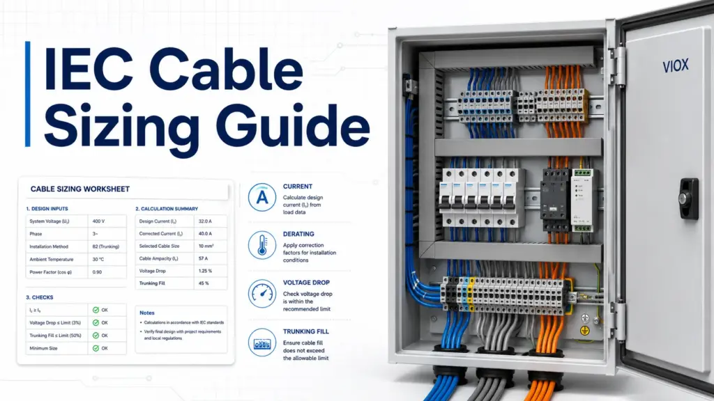
Direct Answer: How Do You Size a Cable for an IEC Low-Voltage Panel?
To size a cable for an IEC-style low-voltage control panel, start with the design current, choose a conductor with enough current-carrying capacity after derating, check voltage drop, verify short-circuit protection, confirm terminal and protective device compatibility, and make sure the cable fits safely inside the trunking or duct.
IEC 60204-1 is important because it covers electrical equipment of machines, including control panels, wiring practices, protective bonding, conductor identification, and verification. But it is not a simple “one-size cable table.” A correct cable size depends on load current, installation method, ambient temperature, grouping, insulation type, protective device rating, voltage drop, fault current, and local project requirements.
Key Takeaways
- Do not select cable size from breaker rating alone. A 32A, 40A, or 63A breaker only tells you the protection level; the conductor must still be checked against installation conditions.
- Cable derating matters. Ambient temperature, grouping inside trunking, insulation material, and installation method can reduce usable ampacity.
- Voltage drop is a separate check. A cable can be thermally safe but still too small for a long run because the equipment receives insufficient voltage.
- Trunking fill affects heat and maintenance. Overfilled trunking makes wiring difficult, increases heat concentration, and reduces future serviceability.
- IEC 60204-1 is a machine electrical equipment standard. For exact cable ampacity tables, designers often also refer to applicable national wiring rules, IEC 60364-based rules, cable manufacturer data, and project specifications.
IEC Cable Sizing Workflow
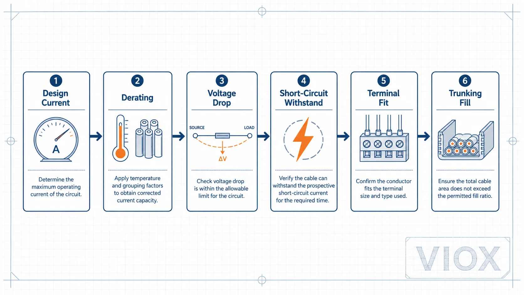
The practical sizing sequence is:
| Step | What to Check | Why It Matters |
|---|---|---|
| 1 | Design current | Establishes the load the cable must carry |
| 2 | Protective device rating | Ensures the breaker or fuse protects the cable |
| 3 | Installation method | Changes allowable current-carrying capacity |
| 4 | Derating factors | Corrects for temperature, grouping, insulation, and enclosure conditions |
| 5 | Voltage drop | Prevents low voltage at motors, power supplies, PLCs, and field devices |
| 6 | Short-circuit withstand | Ensures the cable survives until protection clears the fault |
| 7 | Trunking fill | Ensures heat dissipation, wiring space, and maintainability |
| 8 | IEC 60204-1 panel checks | Covers machine wiring, protective bonding, conductor identification, and verification |
For general electrical formula support, see VIOX’s guide to low-voltage electrical formulas for panel design and maintenance.
Step 1: Calculate the Design Current
Design current is the expected current carried by the cable under normal operating conditions. It is not always the same as the breaker rating.
Single-Phase AC Load
For a single-phase load:
I = P / (V × PF × η)Where:
I= current in amperesP= output or input power in watts, depending on available dataV= supply voltagePF= power factorη= efficiency, if calculating from mechanical output power
For a resistive heater, power factor and efficiency corrections may be simple. For a motor, pump, fan, compressor, or VFD-fed load, check the nameplate or datasheet rather than assuming unity power factor.
Three-Phase AC Load
For a balanced three-phase load:
I = P / (√3 × V × PF × η)Where V is the line-to-line voltage.
This formula is useful for estimating motor feeder current, but final selection should still be checked against the motor full-load current, starting method, overload protection, and manufacturer data.
Step 2: Match the Cable to the Protective Device
The protective device must protect the cable from overload and short circuit. In simple terms, the cable should be able to carry the circuit design current, and the breaker or fuse should disconnect before the cable insulation is damaged.
A common design relationship is:
Ib ≤ In ≤ IzWhere:
Ib= design current of the circuitIn= rated current or setting of the protective deviceIz= current-carrying capacity of the cable after installation conditions are considered
This relationship is a useful engineering rule, but it must be applied with the relevant wiring standard, cable table, protective device curve, and project specification.
If the circuit uses an MCB, the cable size must also coordinate with the breaker’s trip curve and breaking capacity. For related breaker selection, see MCB breaking capacity: 6kA vs 10kA.
Step 3: Apply Cable Derating Factors
Cable tables usually give current-carrying capacity under defined reference conditions. Real control panels rarely match those conditions exactly.
The corrected capacity can be checked conceptually as:
Iz_corrected = Iz_table × Ca × Cg × Ci × CvWhere:
Ca= ambient temperature correction factorCg= grouping correction factorCi= installation method or enclosure correction factorCv= ventilation or other project-specific correction factor
Some designers calculate the required table capacity instead:
Iz_table_required = Ib / (Ca × Cg × Ci × Cv)Both approaches are trying to answer the same question: after real installation conditions are considered, can the cable safely carry the design current?
Common Cable Derating Factors
| Derating Factor | What It Represents | Typical Risk if Ignored |
|---|---|---|
| Ambient temperature | Higher surrounding temperature reduces heat dissipation | Insulation aging, nuisance trips, hot trunking |
| Cable grouping | Multiple loaded cables heat each other | Undersized conductors in crowded duct |
| Installation method | Free air, conduit, tray, trunking, enclosure wiring | Wrong ampacity table selection |
| Insulation material | PVC, XLPE, rubber, silicone, high-temperature cable | Wrong temperature rating assumption |
| Ventilation | Sealed cabinet, forced ventilation, hot machine area | Local overheating |
| Harmonics | Neutral current in non-linear loads | Undersized neutral or overheating |
This is why “63A cable size” cannot be answered responsibly with one number. A 63A feeder in free air, a sealed cabinet, and a hot machine enclosure may need different conductors.
Worked Example: Derating a 40A Feeder in a Control Cabinet
Assume a 40A feeder is installed inside a control cabinet with several other loaded conductors in the same trunking. The cable table value cannot be used directly because the real installation runs hotter than the reference condition.
Example calculation:
Design current Ib = 40A
Ambient correction factor Ca = 0.91
Grouping correction factor Cg = 0.80
Installation/enclosure factor Ci = 0.95

Required table capacity = Ib / (Ca × Cg × Ci)
Required table capacity = 40 / (0.91 × 0.80 × 0.95)
Required table capacity ≈ 57.9A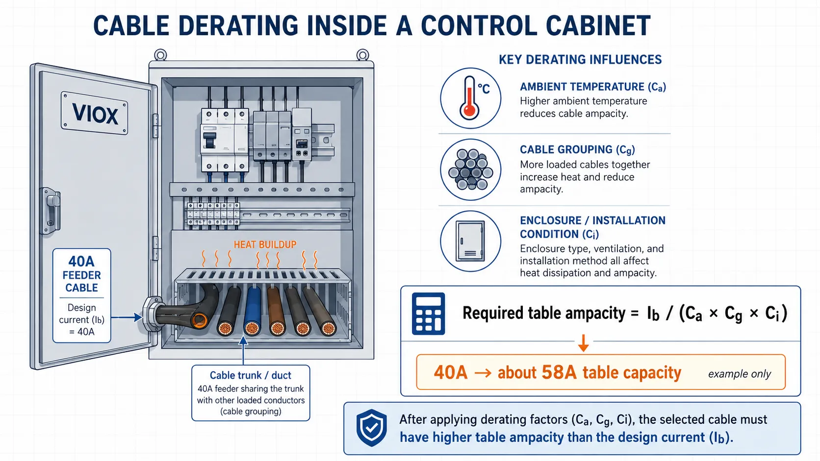
This does not automatically mean the next cable size is correct. It means the selected cable must have a table ampacity of at least about 58A before these correction factors are applied. The final conductor size still depends on insulation type, terminal rating, voltage drop, short-circuit withstand, and local rules.
| Input | Example Value | Engineering Meaning |
|---|---|---|
| Design current | 40A | Actual load current to be carried |
| Ambient factor | 0.91 | Higher temperature reduces usable ampacity |
| Grouping factor | 0.80 | Multiple loaded conductors heat each other |
| Enclosure factor | 0.95 | Cabinet/trunking condition reduces heat dissipation |
| Required table ampacity | About 58A | Cable table value needed before derating |
Step 4: Check Voltage Drop
Voltage drop is the reduction in voltage between the supply point and the load. It becomes important on long cable runs, motor starting circuits, 24V DC control wiring, and field device circuits.
Simplified Single-Phase Voltage Drop
For a two-wire single-phase circuit:
ΔV = 2 × I × L × RWhere:
ΔV= voltage dropI= load currentL= one-way cable lengthR= conductor resistance per unit length
The factor 2 accounts for outgoing and return conductors.
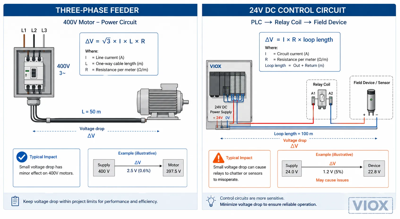
Three-Phase Voltage Drop
For a balanced three-phase circuit:
ΔV = √3 × I × L × (R × cosφ + X × sinφ)Where:
R= conductor resistanceX= conductor reactancecosφ= power factor
For many low-voltage panel calculations, designers use manufacturer-provided mV/A/m voltage drop tables because they are faster and less error-prone.
Voltage Drop Percentage
Voltage drop % = (ΔV / Supply voltage) × 100The acceptable voltage drop limit depends on the project, equipment sensitivity, local rules, and whether the circuit is power, lighting, motor, or control. For control circuits and PLC input circuits, voltage drop can cause intermittent faults even when the cable is thermally safe.
Worked Example: Three-Phase Voltage Drop
Assume a three-phase motor feeder has:
- Load current: 32A
- Cable length: 40 m one way
- Resistance value from cable data: 3.08 ohm/km
- Reactance ignored for a simplified first check
- Supply voltage: 400V
Convert resistance to ohm per meter:
3.08 ohm/km = 0.00308 ohm/mSimplified three-phase voltage drop:
ΔV ≈ √3 × I × L × R
ΔV ≈ 1.732 × 32 × 40 × 0.00308
ΔV ≈ 6.8V
Voltage drop percentage:
Voltage drop % = 6.8 / 400 × 100
Voltage drop % ≈ 1.7%
This simplified result may look acceptable, but motor starting can create a much higher current for a short time. For long motor circuits, check both running voltage drop and starting voltage drop.
Worked Example: 24V DC Control Circuit Voltage Drop
Low-voltage DC control circuits are more sensitive to voltage drop than many engineers expect. A few volts lost in a 400V power circuit may be harmless; a few volts lost in a 24V circuit can stop a relay, sensor, or solenoid from working reliably.
For a 24V DC circuit:
- Load current: 2A
- One-way cable length: 30 m
- Loop length: 60 m
- Conductor resistance: 13.3 ohm/km, or 0.0133 ohm/m
ΔV = I × R × loop length
ΔV = 2 × 0.0133 × 60
ΔV ≈ 1.6V
Voltage drop % = 1.6 / 24 × 100
Voltage drop % ≈ 6.7%In a PLC cabinet, this may be enough to cause intermittent input faults, weak solenoid operation, or relay chatter. For 24V DC circuits, voltage drop should be checked early, not after the machine is already wired.
Step 5: Check Short-Circuit Withstand
A cable must withstand the thermal energy of a short circuit until the protective device clears the fault.
The common adiabatic check is:
S ≥ √(I²t) / kWhere:
S= conductor cross-sectional areaI= prospective short-circuit currentt= disconnection timek= material and insulation constant
This is especially relevant near transformers, main incoming panels, motor control centers, and high-fault-level industrial systems. For miniature breakers, available fault current must also be checked against breaking capacity. VIOX has a separate guide on how to calculate short-circuit current for MCB selection.
Quick Cable Size Examples: 32A, 40A, and 63A
The table below shows how engineers usually approach common circuit ratings such as 32A, 40A, and 63A. It is not a substitute for a project calculation, but it helps explain why the same breaker rating can require different cable sizes in different panels.
| Circuit Current | Typical Application Question | Practical Design Reminder |
|---|---|---|
| 32A | What cable size should be used with a 32A isolator or 32A MCB? | Check whether the load is continuous, motor-starting, single-phase, three-phase, or installed in hot trunking |
| 40A | Is the standard 40A cable size still valid after derating? | Derating and voltage drop may push the conductor larger than a simple ampacity table suggests |
| 63A | What cable size is suitable for a 63A breaker or 63A feeder? | Short-circuit withstand, termination size, trunking fill, and heat rise become more important |
For copper conductors in common low-voltage installations, designers often see approximate ranges such as 4-6 mm² for some 32A circuits, 6-10 mm² for some 40A circuits, and 10-16 mm² for some 63A circuits. These are not universal rules. Final selection must be based on the cable standard, installation method, ambient temperature, conductor insulation, protective device, voltage drop, and local code.
This is the point where many field mistakes happen: the installer chooses a cable from a memory table, but the panel has high ambient temperature, several loaded conductors in the same duct, and a long run to the machine. The result is a cable that looks “normal” on paper but runs hot in service.
Cable Diameter vs Conductor Cross-Section
Searches such as “conductor diameter” and “cable outer diameter” often come from engineers sizing glands, trunking, conduit, or terminal entries.
These are different values:
| Term | Meaning | Why It Matters |
|---|---|---|
| Conductor cross-section | Copper or aluminum area, usually in mm² | Determines current capacity and resistance |
| Conductor diameter | Physical diameter of the conductor | Useful for conductor construction, not enough for cable gland sizing |
| Cable outer diameter | Overall diameter including insulation and sheath | Needed for glands, trunking fill, bending radius, and enclosure entry |
| Cable bending radius | Minimum bend allowed by manufacturer | Prevents insulation damage and conductor stress |
For trunking or gland selection, use the cable manufacturer’s outer diameter, not only the conductor cross-section.
Step 6: Calculate Trunking Fill
Trunking fill is the percentage of the trunking internal area occupied by cables. Overfilled trunking causes heat concentration, difficult maintenance, poor airflow, and higher risk of insulation damage during installation.
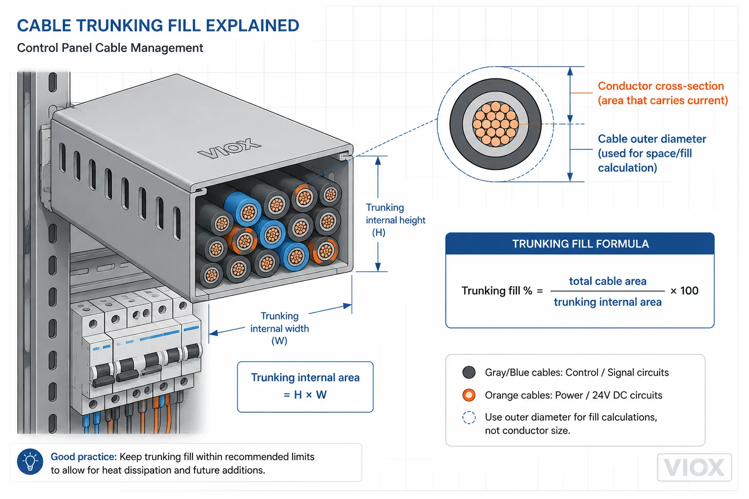
Cable Area
If the cable outside diameter is known:
Cable area = π × d² / 4Where d is the cable outside diameter.
Trunking Fill
Trunking fill % = (Total cable area / Internal trunking area) × 100Many panel builders use a conservative fill target to allow wiring space, airflow, and future maintenance. The exact maximum should be checked against project specifications, panel builder rules, and applicable local standards.
Trunking Fill Example
| Item | Example Value |
|---|---|
| Trunking internal size | 60 mm × 60 mm |
| Internal area | 3,600 mm² |
| Cable outside diameter | 8 mm |
| Area per cable | About 50 mm² |
| Number of cables | 30 |
| Total cable area | About 1,500 mm² |
| Fill ratio | About 42% |
This may be acceptable in one project and too crowded in another, depending on heat, cable grouping, service access, and panel layout.
Practical Trunking Fill Guide for Panel Builders
The right trunking size is not only a math problem. Panel builders also need space for ferrules, wire markers, bends, service loops, cable segregation, and future replacement work.
| Trunking Situation | What It Usually Means | Design Action |
|---|---|---|
| Low fill, clean routing | Easy maintenance and better airflow | Usually preferred for control panels |
| Medium fill with many loaded conductors | Heat and grouping correction become important | Recheck derating and cable grouping |
| High fill near contactors or drives | Hot area plus dense wiring | Increase trunking size or separate circuits |
| Mixed power and signal wiring | Noise and maintenance risk | Use separation, shielding, or separate routes |
| Many 24V DC wires | Voltage drop and terminal density matter | Check loop length and terminal organization |
As a practical rule, do not treat the trunking calculation as “how many wires can physically fit.” Treat it as “how many wires can fit while staying cool, identifiable, serviceable, and compliant with the panel design.”
IEC 60204-1 Checklist Items Related to Cable Sizing
IEC 60204-1 is often searched together with cable sizing because it applies to the electrical equipment of machines. For control panels, it is relevant to more than conductor ampacity.
| IEC 60204-1-Related Topic | What Designers Should Check |
|---|---|
| Conductor selection | Current, voltage drop, mechanical strength, insulation, and installation conditions |
| Protective bonding | Protective earth continuity and bonding conductor adequacy |
| Power and control separation | Avoiding interference, heat, and unsafe routing between different circuit types |
| Wire identification | Conductor colors, numbers, markers, and documentation consistency |
| Control circuits | Correct control voltage, overcurrent protection, and safe circuit design |
| Verification | Continuity, insulation resistance, voltage tests where applicable, and functional testing |
| Documentation | Wiring diagrams, terminal plans, conductor identification, and component data |
For detailed panel work, IEC 60204-1 should be used together with the machine risk assessment, applicable national adoption, equipment manufacturer data, and project specifications.
Some searches around IEC 60204-1 mention wire cross-section requirements, power and signal wire separation, wire colors, 24V control circuits, dielectric testing, and control cabinet verification checklists. Those topics are related to cable sizing, but they are not the same task. Cable sizing decides the conductor; IEC 60204-1 verification checks whether the machine electrical equipment has been wired, identified, protected, bonded, documented, and tested correctly.
IEC 60204-1 vs IEC 60364: Do Not Mix the Contexts
One common mistake is using a building-wiring mindset for machine control panels. IEC 60204-1 and IEC 60364 are related to electrical safety, but they are not used in exactly the same way.
| Topic | IEC 60204-1 Context | IEC 60364 Context |
|---|---|---|
| Main focus | Electrical equipment of machines | Electrical installations of buildings |
| Typical user | Machine builder, panel builder, automation engineer | Electrical contractor, building designer, installation engineer |
| Wiring environment | Control cabinets, machines, moving equipment, actuators, sensors | Building distribution circuits, final circuits, fixed wiring |
| Cable sizing relevance | Machine wiring, control circuits, protective bonding, verification | Installation cable sizing, protective measures, voltage drop, current capacity |
| Practical warning | Do not use it as a standalone ampacity table | Do not ignore machine-specific wiring and control requirements |
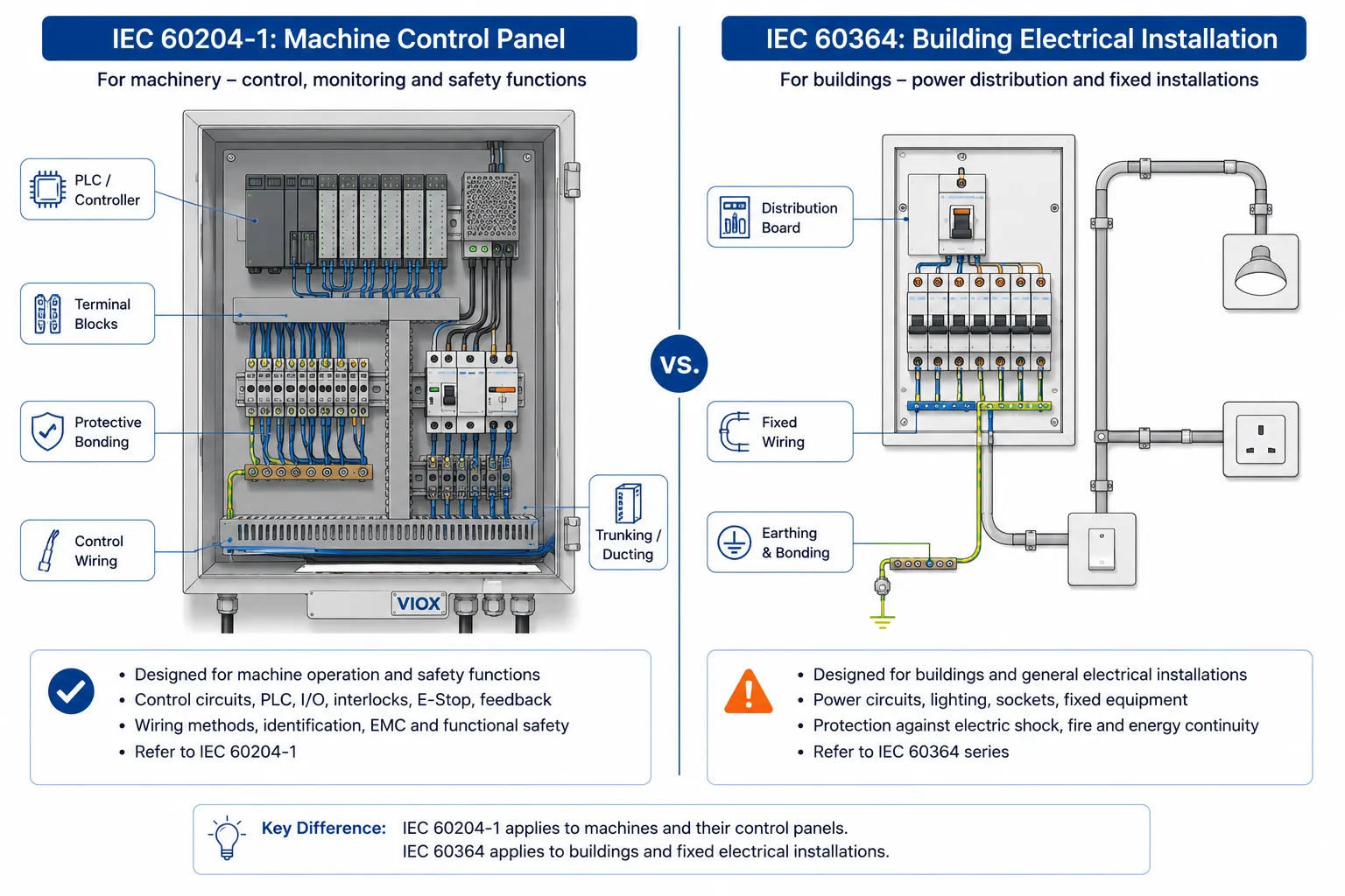
For VIOX readers, the key point is simple: if you are designing a machine control panel, IEC 60204-1 matters. If you are sizing building installation cables, local rules based on IEC 60364 may be more central. Many projects require both viewpoints.
Power Cables vs Control Cables vs Signal Cables
Cable sizing inside industrial panels is not only about ampacity. Different circuits have different failure modes.
| Cable Type | Main Concern | Common Mistake |
|---|---|---|
| Power cable | Current capacity, short-circuit withstand, voltage drop | Sizing only by load current and ignoring fault level |
| Motor cable | Starting current, heat, EMC, voltage drop | Ignoring motor starting and VFD output cable rules |
| 24V DC control cable | Voltage drop, terminal density, identification | Using long thin wires that cause PLC input faults |
| Signal cable | Noise immunity, shielding, separation | Routing next to power cables without considering interference |
| Protective earth conductor | Fault current path and bonding continuity | Treating PE as ordinary signal wiring |
For control panels with contactors, relays, sensors, PLCs, and power supplies, routing and separation can matter as much as cross-section.
Common IEC Cable Sizing Mistakes
| Mistake | Why It Causes Problems | Better Practice |
|---|---|---|
| Selecting cable by breaker rating only | Ignores derating, installation method, and voltage drop | Start with design current and check all correction factors |
| Ignoring grouping in trunking | Multiple loaded cables raise temperature | Apply grouping factor or increase conductor size |
| Using conductor size instead of cable outer diameter for trunking | Underestimates space needed | Use manufacturer cable OD for fill calculation |
| Forgetting voltage drop on 24V DC circuits | PLCs, sensors, and relays may behave intermittently | Check voltage at the load under worst-case current |
| Treating IEC 60204-1 as a cable ampacity table | Misunderstands the standard’s role | Use IEC 60204-1 for machine electrical equipment requirements and use relevant cable tables for ampacity |
| Mixing power and signal wiring without planning | Noise, heating, and maintenance issues | Separate, shield, or route according to circuit type and project rules |
| Not checking terminal compatibility | Cable may fit electrically but not mechanically | Verify terminal cross-section range, ferrule type, and tightening requirements |
Practical Selection Checklist
Before finalizing a cable size, confirm:
- Load current and duty cycle
- Single-phase or three-phase supply
- AC or DC circuit
- Protective device type and rating
- Cable material: copper or aluminum
- Insulation temperature rating
- Installation method: free air, trunking, conduit, tray, cabinet wiring
- Ambient temperature inside the panel or machine area
- Number of loaded conductors grouped together
- Voltage drop at operating and starting conditions
- Short-circuit withstand until protective device operation
- Terminal block, breaker, contactor, and gland compatibility
- Trunking fill and bending radius
- Marking, documentation, and IEC 60204-1 verification requirements
If the cable terminates into distribution blocks or terminal blocks, also check terminal cross-section range and torque guidance from the device manufacturer. VIOX’s guide to power distribution blocks explains why terminal compatibility and SCCR matter in panel wiring.
Full Example: Selecting a Cable for a 63A Panel Feeder
This example shows the workflow rather than prescribing a universal cable size.
Assume:
- Circuit design current: 63A
- Three-phase low-voltage panel feeder
- Cable installed in trunking with other loaded conductors
- Ambient temperature inside cabinet higher than a mild indoor room
- Cable length: 25 m
- Protective device: 63A breaker
1. Start with the design current
Ib = 63AThe cable must carry this current under normal operation.
2. Apply correction factors
Example correction factors:
Ca = 0.91
Cg = 0.80
Ci = 0.95
Required table ampacity = 63 / (0.91 × 0.80 × 0.95)
Required table ampacity ≈ 91AThis means the selected cable must be taken from a table where its reference current-carrying capacity is around 91A or higher before correction. A cable that looks adequate at 63A under ideal conditions may be too small after derating.
3. Check voltage drop
Use the cable manufacturer’s voltage drop data or resistance/reactance values. If the cable run is short, voltage drop may pass easily. If the run is long, voltage drop may push the design toward a larger conductor even when thermal capacity is acceptable.
4. Check short-circuit withstand
The conductor must withstand the prospective short-circuit energy until the breaker clears. Near a transformer or main distribution panel, this check becomes more important than many basic sizing guides suggest.
5. Check termination and trunking
Finally, verify that the chosen conductor fits the breaker terminal, distribution block, cable gland, ferrule or lug, and trunking. A cable that is electrically correct but mechanically difficult to terminate can still create heat and service problems.
| Check | Pass Question |
|---|---|
| Ampacity after derating | Is corrected Iz greater than the circuit requirement? |
| Voltage drop | Is the load voltage acceptable at running and starting conditions? |
| Short-circuit withstand | Can the conductor survive until the protective device clears? |
| Protective device | Does the breaker/fuse protect the conductor and match fault level? |
| Termination | Does the cable fit the terminal, lug, ferrule, or gland correctly? |
| Trunking | Is there enough space for heat, routing, and future maintenance? |
When IEC 60204-1 Is Not Enough by Itself
IEC 60204-1 is essential for machine electrical equipment, but it should not be treated as the only document needed for every cable calculation.
You may also need:
- National wiring rules based on IEC 60364 or local electrical codes
- Cable manufacturer ampacity and voltage drop data
- Machine safety risk assessment
- Protective device time-current curves
- Short-circuit current study
- EMC guidance for VFD, servo, and signal wiring
- Panel assembly requirements where IEC 61439 or local panel standards apply
In other words, IEC 60204-1 gives the machine electrical equipment framework. Cable sizing still requires engineering calculation.
FAQ
What is IEC cable sizing?
IEC cable sizing means selecting a conductor using IEC-style engineering principles: design current, current-carrying capacity, derating, voltage drop, protective device coordination, short-circuit withstand, and installation conditions.
Does IEC 60204-1 give cable size tables?
IEC 60204-1 is mainly a machine electrical equipment standard. It is relevant to wiring and conductor selection, but designers normally use applicable cable tables, national wiring rules, manufacturer data, and project requirements for exact ampacity values.
What cable size is needed for a 32A MCB?
There is no universal answer. A 32A circuit may use different conductor sizes depending on installation method, ambient temperature, cable insulation, grouping, voltage drop, and local code. Treat common sizes such as 4-6 mm² copper only as a starting reference, not a final design.
What cable size is needed for a 63A breaker?
A 63A circuit often requires a larger conductor such as 10-16 mm² copper in many practical cases, but final sizing must be calculated. Long cable runs, hot panels, grouped conductors, aluminum cable, or high fault levels can change the answer.
What is a cable derating factor?
A cable derating factor reduces the usable ampacity of a cable when real installation conditions are worse than the reference conditions in a cable table. Common factors include temperature, grouping, installation method, ventilation, and insulation type.
How do I calculate trunking size?
Calculate the total outside area of all cables using their outer diameters, then divide by the internal trunking area. Keep enough spare space for heat dissipation, future maintenance, and safe wiring practice.
Why does a 24V control circuit need voltage drop checking?
At 24V, even a small voltage drop can cause PLC inputs, relays, sensors, and solenoid valves to behave unpredictably. Long runs and small conductors are common causes of intermittent control faults.
Is cable outer diameter the same as conductor size?
No. Conductor size is the metal cross-section, such as 2.5 mm² or 6 mm². Cable outer diameter includes insulation and sheath, and it is the value used for glands, trunking fill, and bending space.
Conclusion
IEC cable sizing is not a single table lookup. A safe low-voltage panel cable must pass current capacity, derating, voltage drop, short-circuit withstand, terminal compatibility, and trunking fill checks.
For IEC 60204-1 machine panels, the best approach is to use a structured workflow: calculate design current, apply derating, verify voltage drop, check protection coordination, then confirm wiring layout and documentation. That is how panel builders avoid hot cables, nuisance trips, PLC faults, and failed inspection.
